Table of Contents
Advertisement
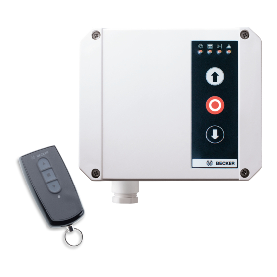
BECK-O-TRONIC 4
Version: Centronic
en
Assembly and Operating Instructions
Door control unit
Important information for:
• Fitters / • Electricians / • Users
Please forward accordingly!
These instructions must be kept safe for future reference.
Becker-Antriebe GmbH
Friedrich-Ebert-Straße 2-4
35764 Sinn/Germany
www.becker-antriebe.com
Advertisement
Table of Contents


Need help?
Do you have a question about the Centronic Series and is the answer not in the manual?
Questions and answers