Table of Contents
Advertisement
Advertisement
Table of Contents

Related Manuals for Commonplace Robotics Mover 4

Summary of Contents for Commonplace Robotics Mover 4
- Page 1 Bedienungsanleitung Mover4...
- Page 3 User Guide Mover4 Version 2016/11 (SW V902-09, HWE 2MV23 HWM V05 DOC V15) © Commonplace Robotics GmbH, 2011 - 2016 Commonplace Robotics GmbH Osterfeldstr. 1 D-49326 Melle Germany ++49 5429 / 374983-4 info@cpr-robots.com www.cpr-robots.com The CE sign confirms that this product meets the requirements of the directive 2004/108/EC (EMC) and 2002/95/EC (RohS).
-
Page 4: Table Of Contents
Inhalt Safety Instructions..........................6 Introduction ............................7 Product .............................. 7 Specifications ..........................8 System Requirements ......................8 Installation .............................. 9 Setting up the Robot ......................... 9 Connecting the Power Supply and the USB Adapter ..........9 Installation of the CPRog Software ................. 10 Installation of the Driver for the USB Adapter............ - Page 5 Program Elements ........................23 Recording a Program using the 3D Interface ............. 24 Saving and Loading of a Program ..................24 Replay of a Program ....................... 24 Editing a Program with GraphEdit ..................25 Editing a Program with TextEdit ..................25 Configuration .............................
-
Page 6: Safety Instructions
1. Safety Instructions The Mover4 is designed to be used by adolescents and adults in edutainment and research areas. The robot must not be used in industrial production facilities of in other continuous operation scenarios. Do not operate the robot when it is unattended. ... -
Page 7: Introduction
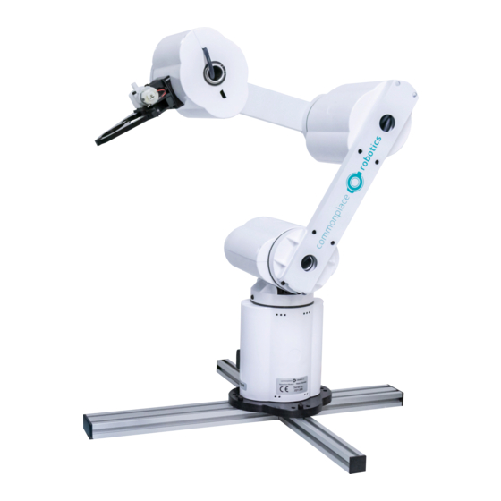
2. Introduction 2.1 Product The Commonplace Robotics Mover4 is a four axis robot for the use in education, entertainment and research environments. The robot can lift a payload up to 500 g with a reach of 500 mm plus gripper. -
Page 8: Specifications
2.2 Specifications Nr of Joints 4 servo joints Power Supply 12V DC at max 5 A Power Consumption Paused: 0,5 A / in motion: < 2.5 A. Fuse with 2.5 A in base Communication CAN at 500 kBit/s Reach 455 mm plus gripper Payload 500 g Inputs / Outputs... -
Page 9: Installation
3. Installation 3.1 Setting up the Robot The robot has to be placed on a table or stand so that he cannot tumble down. 3.2 Connecting the Power Supply and the USB Adapter Pic. 2: Cable loom and USB adapter The cable loom connects the power supply, the USB adapter and the robot as depicted above. -
Page 10: Installation Of The Cprog Software
3.3 Installation of the CPRog Software Insert the CPRog CD into the drive. Depending on your systems configuration the CD menu will open automatically, or you have to start it manually: D:\.autorun\autorun.exe Choose the first button „CPRog Installation” Maybe you have to allow changes to be made on your system. - Page 11 The installation normally takes only a few seconds. The installer checks, if DirectX 9.5 is installed. If not it will install theses libraries from the CD or via download. This will take some minutes. The installation of DirectX 9.5 is necessary even if e.g.
-
Page 12: Installation Of The Driver For The Usb Adapter
3.4 Installation of the Driver for the USB Adapter The robot is delivered with the PCAN USB driver from www.peak-system.com. To run the adapter the according driver has to be installed. This can be done from the CPRog installation CD (button “Install USB-CAN adapter”), or using the manufacturers installation CD. -
Page 13: Licensing
3.5 Licensing The CPRog software needs a license key to start. This key is in most cases already integrated into the installation version of CPRog. Nothing has to be done. If it is not, e.g . because you have installed a demo version, please see the following information. -
Page 14: Robot Arm Mover4
4. Robot Arm Mover4 4.1 Geometry Pic. 3: Mover4 simplified side view The picture shows the joints length of the Mover4 robot arm. Including the gripper the arm reaches 550 mm. CPRog offers functionalities to limit the workspace, see section 7.2. -
Page 15: Digital Inputs And Outputs
4.2 Digital Inputs and Outputs The robot base shows a D-Sub plug with several digital inputs and outputs. The pin assignment is shown below. 24V DIO, D-Sub Male Pin 1: Out1 24V Pin 2: Out2 24V Pin 3: Out3 24V Pin 4: In1 Pin 5: In2 Pin 6: In3... -
Page 16: Drawing Of The Robot Base
Pin1: 12V, max 0.5A Pin2 GND Pin3: DOut 11 (5V TTL) Pin4: DOut 12 (5V TTL) Pin5: not connected Pin 6: not connected Pic. 5: Drawing of the flange 4.4 Drawing of the Robot Base The robot can be mounted using the M4 through holes. Pic. -
Page 17: Moving The Robot Arm With Cprog
5. Moving the Robot Arm with CPRog 5.1 Introduction The CPRog programming environment allows to control and program the Mover robot. Both online and offline working is possible. Pic. 7: CPRog User Interface In the upper area the three ribbons “Scene”, “Motion” and “Programming” provide access to the main functionalities. -
Page 18: Navigation Using The Mouse
5.2 Navigation using the Mouse A 3 button mouse is recommended to navigate in the CPRog 3D environment: Left button: Selection of robots and other objects Middle button: Navigation in the scene o Rotate: drag the mouse while holding the middle button o Pan: drag the mouse while holding the middle button and pressing down the CTRL-key o Zoom: Drag the mouse while holding the middle button and pressing... - Page 19 The „Joint“ mode allows to turn the single robot axis from A1 to A4. In “Cartesian” mode the robot moves in straight lines following the x, y and z coordinate axis. The rotation is defined with the B commands. In „Cartesian Tool” mode the robot moves aligned to the current tool coordinate system.
-
Page 20: Moving The Robot Using The Graphics
5.4 Moving the Robot using the Graphics An alternative to the joypad is to drag the robot in the graphical 3D environment. When selecting a joint of the robot with the left mouse button, the joint outlines blink red. When selecting the joint and moving the mouse with pressed left mouse button this joint will rotate forward or backward, depending on the mouse motion. -
Page 21: Reset The Zero Points Of The Joints
Step 1: Connect with the hardware. This step initializes the USB-CAN interface. The LED on the left side of CPRog changes color from grey to red. Below the LED several error messages are displayed. Step 2: Reset the errors. This button resets the error memory of the joint module controller in the robot. - Page 22 When the robot is in the correct position press “LogoCircle/Configuration/SetJointsToZero” in the upper left menu. Confirm the following dialog with „OK“. This function takes back the motor enabling, so the error reset and enable motor buttons have to be pressed. The precision of the calibration is vital for replaying old programs.
-
Page 23: Programming The Robot Arm With Cprog
6. Programming the Robot Arm with CPRog 6.1 Program Elements A Mover4 robot program is build out of the following commands: The robot moves on a straight line from the current position to the target position. The velocity is defined in mm/s. Joint Interpolates the axis from the current position to the target position in joint coordinates. -
Page 24: Recording A Program Using The 3D Interface
The complete language specification is found in section Fehler! Verweisquelle konnte nicht gefunden werden. . 6.2 Recording a Program using the 3D Interface Using the 3D screen a program can be recorded using the joypad or the buttons. Joypad: Every time the A button (or button 2) on the joypad is pressed a linear command to the current robot position is recorded. -
Page 25: Editing A Program With Graphedit
The buttons in the area Motion/Programs allow to replay, pause and stop a program. The replay can be done in single, repeat or step mode. 6.5 Editing a Program with GraphEdit The button Programming/Editor opens a graphical program editor. This editor allows in a puzzle visualization to adapt and create programs. - Page 26 Using the button beneath GraphEdit opens the TextEdit Program editor. This editor is more usable for bigger programs and provides more information. The editor contains a syntax check. Illegal cells are marked red, the syntax for the command is shown in the bottom line as an assistance. When there are errors in the program it cannot be saved.
- Page 27 When choosing ‘Save’ from the File menu the current program is written and loaded by the robot. So the robot is again in synch with the text editor. When choosing ‘Save As’ from the File menu the current program is saved under a different name.
-
Page 28: Configuration
7. Configuration 7.1 Application Configuration The application configuration can be done by adapting the parameters in different XML files. 7.1.1 Startup Configuration The file c:\CPRog\CPRFrontend.xml allows to set the language and the start project. <Program Language="DE"/> Possible choices are DE and EN. <StartUp Project="..\..\Data\Projects\Mover4Basic.prj"... -
Page 29: Robot Configuration
7.2 Robot Configuration For each robot in the CPRog simulation a XML config file exists, e.g. C:\CPRog\Data\Robots\CPRMover4\CPRMover4.xml Definition for the velocities in Jog mode: <Velocities JogCart="200.0" JogOri="45.0" JogJoint="1.0"/> A virtual cell can be defined as a safety space the robot cannot leave in Cartesian mode: <VirtualBox active="false"... -
Page 30: Interfacing
8. Interfacing 8.1 CRI Interface The CRI interface allows to connect via Ethernet and jog the robot, send motion commands and start programs. With this setup you can use the CPRog functionalities and implement custom algorithms in a CRI client, e.g. a vision system. Possiblities then are e.g.: ... -
Page 31: Ros - Robot Operating System
8.2 ROS – Robot Operating System The Willow Garage Robot Operating System (see www.ros.org) is wide spread in the research community, especially when dealing with service robots. For the Mover4 packages are available to connect with the hardware and to command the robot by joint and position messages. -
Page 32: Can Protocol Specification
9. CAN Protocol Specification The Mover4 uses the CPR-CAN protocol, a custom CAN protocol with 16 bit position data width. The protocol description is available on our Wiki in the Interfacing section: http://wiki.cpr-robots.com Please refer also to the C++ implementations found on www.githu.com/CPR-Robots for code examples. -
Page 33: Error Codes
10. Error Codes The robot provides two means of error indications, via the inner LED and via the CAN bus. 10.1.1 Red LED on the control module This LED can be seen through the single holes in the robots hull. Off: No error One fast blink every second:... - Page 34 Bit 4 Interval without command Provide the position or velocity Comm was too long commands in a reliable and short Watch enough time interval. Increase maxMissedCom. Bit 5 Position is too far away from Provide setpoint positions Position the setpoint position reachable to the current motor position.
-
Page 35: Troubleshooting
11. Troubleshooting This section offers approaches to solve problems and errors in the areas Installation, Software and Hardware. If these measures do not solve your problem please get in contact with us, we are happy to help: Mail: service@cpr-robots.com Please add a description of the problem, the robots serial number (found at the base) and the three files „install.log“, „startUpLog.txt“... -
Page 36: Hardware Mover4
messages may be too long. the virus scanner. Does not move any more: When moving in „Cartesian Change to JointMode and move the Message “Virtual Box Mode” the robot cannot get robot back into the virtual Box, e.g. violated” and warning out of a virtual box. -
Page 37: Language Specification
12. Language Specification The following nine commands can be combined to form a robot program. A program is a XML file that starts with the lines <?xml version="1.0" encoding="utf-8"?> <!-- values in mm and degree --> <Program> <Header ProgramName ="CPRog recording"... - Page 39 © Commonplace Robotics November 2016...
Need help?
Do you have a question about the Mover 4 and is the answer not in the manual?
Questions and answers