
Related Manuals for Philips MML1941-PCR


Summary of Contents for Philips MML1941-PCR
- Page 1 User’s Manual LCD 19” MONOCHROME MONITOR MML1941-PCR MML1942-PER Rev. 1.0 MML194x...
- Page 2 INTENTIONALLY LEFT BLANK MML194x...
-
Page 3: Table Of Contents
000 – 300 ) .... 36 MBIENT IGHT OMPENSATION DIMENSIONS ..............11 ............... 36 MML1942-PER ............... 11 - DVI ..............36 MML1941-PCR ............... 12 ................37 ERVICE ............... 38 FFSET INSTALLATION ..............13 ..............38 FFSET REEN MOUNTING INSTRUCTION ..........14 .............. -
Page 4: Introduction
INTRODUCTION The PHILIPS Medical Grade MML194x is a monochrome active matrix, liquid crystal display exclusively designed for medical imaging applications. The monitor can be used for X-ray and PACS and other medical systems requiring a very high level of image quality for examination and control purpose and can accept an analogue signal input as well as a digital input. -
Page 5: Caution
This manual is covered by Copyright with all rights reserved. Under the copy rights law, this manual may not be copied, in whole or part, without written consent of Philips. Under the law, copying includes translating into another language or format. -
Page 6: Precautions
PRECAUTIONS Installation Power cord: due to the different power cable lengths necessary at system level, the power cable is not provided with this LCD monitor. in Europe, use a power cord H05VV-F or H05VVH2-F rated 0.75mm 250V, with a Plug rated 10A 250V. At least one European safety mark is required. -
Page 7: Serviceability
Serviceability There are no User serviceable parts within the 19” LCD monitor. Attempting to open or disassemble the monitor may expose the User to hazardous voltages, risk of excessive temperatures, fire or explosion from enclosed energy sources, or impairment of function. -
Page 8: Disposal Of The Lcd Monitor
For the design of MML194x LCD monitors, special attention has been placed to the environmental impact of the product: packaging, product’s weight and energy consumption have been optimized vs. its performances. Then, please consider the following notes in the disposal of the product. The monitor’s packaging is re-usable, please retain the packaging for future use. -
Page 9: Product Disposal Information
According to what declared by our components supplier, this product is RoHS compliant. Directive 1907/2006/EC on Registration, Evaluation, Authorization and Registration of Chemicals (REACH) Information on REACH Substances of Very High Concern (SVHCs) in our products can be found on the PHILIPS website . The information will be regularly updated. -
Page 10: Technical Information
8-bit Dimensions 425 x 375 x 96,8 mm (width x height x depth.) Weight 5560g (MML1942-PER), 7580g (MML1941-PCR), 2380g ( pedestal ) Active display area 376.32 x 301.056 mm ( width x height ) Response Time 40 ms ( 10% to 90% rising + 90% to 10% falling ) Viewing Angle ±... -
Page 11: Dimensions
DIMENSIONS MML1942-PER MML194x... -
Page 12: Mml1941-Pcr
MML1941-PCR MML194x... -
Page 13: Installation
• 4 VESA Screws M4x30mm 4519 200 40441 (mounted in VESA holes) • 4 Lock washer 4519 200 40191 (mounted in VESA holes) • 4 Plain washer 4519 200 40201 (mounted in VESA holes) MML1941-PCR • Monitor • This User’s manual •... -
Page 14: Mounting Instruction
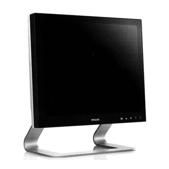
MOUNTING INSTRUCTION Pedestal (MML1941-PCR) With the built-in pedestal the monitor can be tilted for a most comfortable viewing angle as shown in figure here below. VESA Plate (MML1942-PER) The arm with VESA (100mm x 100mm) interface must be fixed to the monitor with the 4 screws already present on the back cover. -
Page 15: Connecting Instruction
CONNECTING INSTRUCTION Additional Protective Earth Pin The position of the external ground safety connector (to fix by screw with lock washer M4x12 max) is indicated in the figure below. Protective earth pin MML194x... - Page 16 Connecting AC Power Plug the receptacle end of the cord set into the AC power adapter, then plug the power connector of the adapter into the power port on the monitor. This power port is located on the back of the monitor (see figure below). The power cord set can be fixed to cabinet with proper cable clamp and screw (see figure below).
- Page 17 Connecting analog video (SXGA) Connect the supplied video cable from the monitor to the computer’s video port (see figure below) only when the computer and the monitor are turned off. Make sure the video cable connector is securely connected to the video port on the computer. MML194x...
- Page 18 Connecting composite video - BNC Connect a BNC video cable from the monitor to the computer’s video port (see figure below) only when the computer and the monitor are turned off. For example: connection between MML1942-PER and Image source via BNC cable. Connecting digital video (DVI) Connect a DVI video cable from the monitor to the computer’s video port (see figure below) only when the computer and the monitor are turned off.
-
Page 19: Input Instruction
INPUT INSTRUCTION Mains switch 12A - 125/250V~ AC inlet (Meet IEC 320/CEE 22 STANDARD) 100/240V~ RS232 Connector (RJ11-4) Pin 1 : RS232 RX Pin 2 : RS232 TX Pin 3 : V sense 3,3V Pin 4 : GND DVI input Connector (Microcross™ DVI-I female connector) Pin 1 : D2_RX - (T.M.D.S.) Pin 13 : D3_RX + (T.M.D.S.) Pin 2 : D2_RX + (T.M.D.S.) -
Page 20: Control Panel Description
Decrease brightness - BRIGHTNESS ADJ- ▼ - MENU SELECT - Move cursor in OSD ▲ - MENU SELECT + Recall brightness Preset/Move cursor in OSD - ENTER (Store/Select) PHILIPS - LOGO Turn keyboard backlight ON (touch PHILIPS logo for 2.5s) MML194x... -
Page 21: Brightness Key Functions
5s the MML194x enters the stand-by mode (the panel is black and the front LED is orange). Touch ENTER for 1s to switch back to Normal mode PHILIPS - LOGO When touched for at least 3s, it turns the backlight illumination of the keypad ON and OFF (toggle mode). - Page 22 Keyboard Lock/Unlock To prevent unintentional access to the OSD menu, the keyboard can be locked. If the Keyboard Status is locked, any access either to OSD or to the brightness control keys are inhibited. - By touching any OSD key, the dialogue here below appears Access to the OSD menu is granted only after touching the following key sequence: •...
-
Page 23: Osd - On Screen Display
OSD - ON SCREEN DISPLAY MENU STRUCTURE MENU SUBMENU ITEM NOTE │ │ │ │ │ ├───── MAIN ┐ Highlighted text indicates default selection │ ├───── INFORMATION │ ├───── LANGUAGE ┐ │ │ ├───── ENGLISH │ │ ├───── FRANÇAIS │ │... -
Page 24: Osd Key Functions
OSD KEY FUNCTIONS Function Description Enter It activates the OSD MAIN MENU if this is not active, otherwise selects and executes a desired OSD Special Function. Adjust When main menu or sub-menu is active, it allows to move or scroll to the next (down) item or adjust the parameter. -
Page 25: Main Menu
Main menu After the activation of OSD Main menu the following window appears 1) Touch Enter to enter in Sub-menu of Main menu 2) Touch the Adjust + or Adjust - button until the desired item is highlighted. 3) When the desired Sub-menu is highlighted, touch the Enter and the Item is highlighted 4) Touch Adjust + or Adjust - button to adjust the value or to select the desired sub-menu and touch again Enter to confirm. -
Page 26: Information
Information 1) Touch Enter button when the Information is highlighted on Main menu. The Information window appears: MML19 Model D1.15H - 04 - LP03 Firmware Release h00002 Operating Hours xxxx Warning 1 xxxx Warning 2 3) Touch Enter button to return to Main Menu. 4) Touch the Adjust + or Adjust - button to exit or to select another item Note:... -
Page 27: Key Lock
Key Lock 1) Touch Enter button when the Key Lock is highlighted on Main Menu. The Key Lock window appears: The ON SCREEN DISPLAY shows the following available choices: - Disabled - Enabled 2) Touch the Adjust + or Adjust - button until the desired item is highlighted. -
Page 28: Osd Vert. Pos
OSD Vert. Pos. 1) Touch Enter button when the OSD Vert. Pos. is highlighted on Main Menu. The OSD Vert. Pos. window appears: 2) Touch the Adjust + or Adjust - button until the desired value appears. 3) Touch the Enter button to confirm your selection. 4) Touch the Adjust + or Adjust - button to exit or to select another item MML194x... -
Page 29: Image Adjust
Image Adjust After the activation of Image Adjust menu the following window appears: 1) Touch Enter to enter in Sub-menu of Image Adjust menu 2) Touch the Adjust + or Adjust - button until the desired item is highlighted. 3) When the desired Sub-menu is highlighted, touch the Enter and the Item is highlighted 4) Touch Adjust + or Adjust - button to adjust the value or to select the desired sub-menu and touch again Enter to... -
Page 30: Hor. Position
Hor. Position 1) Touch Enter button when the Hor. Position is highlighted on Image Adjust Menu. The Hor. Position window appears: 2) Touch the Adjust + or Adjust - button until the desired value appears. 3) Touch the Enter button to confirm your selection. 4) Touch the Adjust + or Adjust - button to exit or to select another item Vert. -
Page 31: Lut
1) Touch Enter button when the LUT is highlighted on Image Adjust Menu. The LUT window appears: The ON SCREEN DISPLAY shows the following available choices, you can select: - Linear The Transfer Function is transparent - Dicom The output curve follows the DICOM curve - CAL. -
Page 32: Border Color
Border Color 1) Touch Enter button when the Border Color is highlighted on Image Adjust Menu. The Border Color window appears: 2) Touch the Adjust + or Adjust - button until the desired value appears. 3) Touch the Enter button to confirm your selection. 4) Touch the Adjust + or Adjust - button to exit or to select another item Freeze 1) Touch Enter button when the Freeze is highlighted on Image Adjust... -
Page 33: Advanced
Advanced 1) Touch Enter to enter in Sub-menu of Advanced menu 2) Touch the Adjust + or Adjust - button until the desired item is highlighted. 3) When the desired Sub-menu is highlighted, touch the Enter and the Item is highlighted 4) Touch Adjust + or Adjust - button to adjust the value or to select the desired sub-menu and touch again Enter to confirm. - Page 34 Phase Adjust 1) Touch Enter button when the Phase Adjust is highlighted on Advanced Menu. The Phase Adjust window appears: 2) Touch the Adjust + or Adjust - button until the desired value appears. 3) Touch the Enter button to confirm your selection. 4) Touch the Adjust + or Adjust - button to exit or to select another item Clock Adjust 1) Touch Enter button when the Clock Adjust is highlighted on Advanced...
- Page 35 Auto Phase 1) Touch Enter button when the Auto Phase is highlighted on Advanced Menu. The Auto Phase window appears: 2) Touch the Enter button to confirm your selection and run the automatic adjustment procedure. 3) Touch the Adjust + or Adjust - button to exit or to select another item NOTE: It is not allowed to run the procedure more than one time: to execute it again, Exit the item first.
- Page 36 AIC (Ambient Light Compensation 000 – 300 lux) 1) Touch Enter button when the AIC is highlighted on Advanced Menu. The AIC window appears: 2) Touch the Adjust + or Adjust - button until the desired value appears. 3) Touch the Enter button to confirm your selection. 4) Touch the Adjust + or Adjust - button to exit or to select another item Note: Phase Adjust, Clock Adjust, Auto Clock, Auto Phase, Video Calibration, Restore Factory are valid only in analog video source.
-
Page 37: Service
Service After the activation of Service menu the following window appears 1) Touch Enter to enter in Sub-menu of Service menu 2) Touch the Adjust + or Adjust - button until the desired item is highlighted. 3) When the desired Sub-menu is highlighted, touch the Enter and the Item is highlighted 4) Touch Adjust + or Adjust - button to adjust the value or to select the desired sub-menu and touch again Enter to confirm. - Page 38 Offset Red 1) Touch Enter button when the Offset Red is highlighted on Service Menu. The Offset Red window appears: 2) Touch the Adjust + or Adjust - button until the desired value appears. 3) Touch the Enter button to confirm your selection. 4) Touch the Adjust + or Adjust - button to exit or to select another item Offset Green 1) Touch Enter button when the Offset Green is highlighted on Service...
- Page 39 Gain Red 1) Touch Enter button when the Gain Red is highlighted on Service Menu. The Gain Red window appears: 2) Touch the Adjust + or Adjust - button until the desired value appears. 3) Touch the Enter button to confirm your selection. 4) Touch the Adjust + or Adjust - button to exit or to select another item Gain Green 1) Touch Enter button when the Gain Green is highlighted on Service...
- Page 40 Daisy Address 1) Touch Enter button when the Daisy Address is highlighted on Service Menu. The Daisy Address window appears: The ON SCREEN DISPLAY shows the following available choices: - 1 to -9 - A to -F 2) Touch the Adjust + or Adjust - button until the desired value appears. 3) Touch the Enter button to confirm your selection.
-
Page 41: Exit
Exit After the activation of Exit menu the following window appears MML194x... -
Page 42: Warning Messages
WARNING MESSAGES Check Input Signal If the Video Signal is not available for the selected Video Source a warning message pops-up on the screen for about When the monitor is properly calibrated (No warning messages in the information item) the displayed message is the following: XXX= Current Video Source (BNC, DVI, DSUB, DVI-A) After about 15s the monitor enter the Stand-By mode. -
Page 43: Video Modes
VIDEO MODES H. freq. Resolution V. freq. H. freq. Resolution V. freq. (kHz) (Hz) (kHz) (Hz) 31.5 640x350 61.0 1024x768 37.8 640x350 44.6 1088x612 37.8 640x400 45.9 1088x612 31.5 720x400 45.9 1088x612 31.5 640x480 47.5 1088x612 35.0 640x480 54.1 1152x864 37.5 640x480 63.9... -
Page 44: Identification Label
IDENTIFICATION LABEL RATING LABEL CONTENT Code Number (12NC) Model Number Date of Manufacture Serial Number: AN00yyww001001 AN =Original Code (FIMI) Factory Address 00 =Technical Level yy =Year (12=2012) ww =Week (01 to 52) 001001= Progressive Number MML194x... -
Page 45: Symbols
SYMBOLS The following symbols may appear on the product or its accessory: WARNING: this symbol alerts the User that important information concerning operation and maintenance are provided. The information should be read carefully WARNING: dangerous voltage Disconnect supply before service Compliance with 2002/96/EC (WEEE Directive) Consult instructions for use Compliance with Demko IEC/EN 60601 (Medical Standard) -
Page 46: General Definitions
GENERAL DEFINITIONS Abbreviations European Conformity DEMKO Danish Conformity Mark CCFL Cold Cathode Fluorescent Lamp Canadian Standardization Authority CVBS Composite Video Blanking and Sync Digital Visual Interface EEDID Enhanced Extended Display Identification Data Electromagnetic Compatibility Electrostatic Discharge Federal Communications Commission Field Replaceable Unit Hot Plug Detect (DVI) International Electrotechnical Commission (Standards) 60601-1 Medical electrical equipment requirements... - Page 47 INTENTIONALLY LEFT BLANK MML194x...
- Page 48 FIMI S.r.l. Saronno - Italy All rights are reserved. Reproduction in whole or in part is prohibited without the written consent of the copyright owner Product specification subject to change without notice. Printed in Italy (Rev. 1.0) 4519 206 1098.2 4519 206 1098.2...
Need help?
Do you have a question about the MML1941-PCR and is the answer not in the manual?
Questions and answers