Advertisement
Quick Links
Advertisement

Related Manuals for jbc SFR-A


Summary of Contents for jbc SFR-A
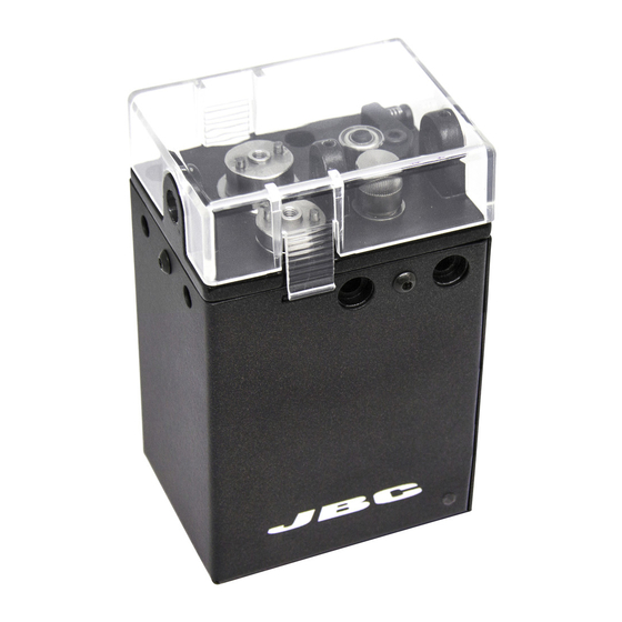
- Page 1 INSTRUCTION MANUAL Solder Feeder for Automation Ref. SFR-A...
-
Page 2: Packing List
Solder Feeder for Reel Support ....1 unit Spanner 10 mm..... 1 unit Automation ....1 unit Ref. 0021219 Ref. 0017631 Ref. SFR-A Allen Key 1,5 mm ..1 unit Allen Key 2,5 mm ..1 unit Communications Ref. 0741610 Ref. 0012574 Cable 3 m...... - Page 3 Communications Connector or device is blocked Connection The Solder Feeder for Automation must be controlled by a Robot/PLC/Computer. JBC developed RS232 Robot Communication Protocol. (Available at www.jbctools.com/jbcsoftware.html) The SFR-A can be connected with a five-pins communications cable (Ref. 0020261). See the table below for a description of Communication Connector pin distribution:...
- Page 4 Assembly: GSFR* Wheels to SFR For this operation, disconnect the device, and dismantle the Cover by pushing the tabs. Use the allen key and the spanner to assemble the following components. 1. Insert the Intermediate Nozzle until its collar rests against the housing and tighten the screw. 2.
- Page 5 5. Finally attach the Reel Support to the SFR with its screws. Reel Support Ref. 0021219 Soldering Head for Automation* Ref. RBA-A Screws Ref. 0490180 Screws Ref. 0014954 Solder Feeder GSFR Guide Tube* for Automation Ref. SFR-A Outlet Nozzle* GSFR Bushing* *Not included, sold separately...
- Page 6 Solder Feeder Screws for Automation Ref. 0014954 Ref. SFR-A If mounting SFR independently from RBA, the Electrical Insulator is required. Assemble the Insulator to your device with its screws, followed by the SFR to The insulator with its screws. The Electrical Insulator must be assembled for the tool to work properly.
- Page 7 w w w.jbctools.com Solder Wire Loading The GSFR must be assembled previously. 1. Feed the Solder Wire into the Inlet Nozzle until it reaches the wheels. 2. Make sure the wire passes through the Intermediate Nozzle and enters into the Guide Tube. Wire feeding is controlled by an external controller (Robot/PLC/Computer).
- Page 8 Dimensions (in) Solder Wire Reel dimensions: max. lenght 80mm (3.2 in), max. diameter 80mm (3.2 in), max. weight 1 kg (2.2 lb).
- Page 9 w w w.jbctools.com Accessories Guide Kit for SFR with Solder Wire Perforation Ref. GSFRXXVXX Guide Tube Blade Clamp Guide Wheel Inter. Nozzle Outlet Nozzle Inlet Nozzle Blade Guide Kit for SFR without Solder Wire Perforation Ref. GSFRXXDXX Guide Tube Traction Wheel Support Wheel Outlet Nozzle Inter.
- Page 10 Work Place Example Soldering Head* Ref. RBA-A Solder Feeder Ref. SFR-A Soldering Iron* Ref. TR245-A Guide Kit* TR470-A Ref. GSFR TRA245-A TRA470-A Control Unit* Tip Cleaner* Ref. UCR245-5A Ref. CLMR-A UCR470-5A Automatic Cartridge Stand* Ref. CS2R245-A CS2R470-A *Not included, sold separately...
-
Page 11: Maintenance
- Use a damp cloth to clean the Solder Feeder. Alcohol can only be used to clean the metal parts. - Periodically check all cables and tube connections. - Replace any defective or damaged parts. Use original JBC spare parts only. - Repairs should only be performed by a JBC authorized technical service. -
Page 12: Specifications
M8-5 pin Commmunication Connector Complies with CE Standards. ESD safe. Warranty JBC’s two-year warranty covers this equipment against all manufacturing defects, including the replacement of defective parts and labour. Warranty does not cover product wear or misuse. In case of any manufacturing defect, the equipment must be returned, postage paid, to the dealer where it was purchased.
Need help?
Do you have a question about the SFR-A and is the answer not in the manual?
Questions and answers