Advertisement
51000-355 / 51000-357
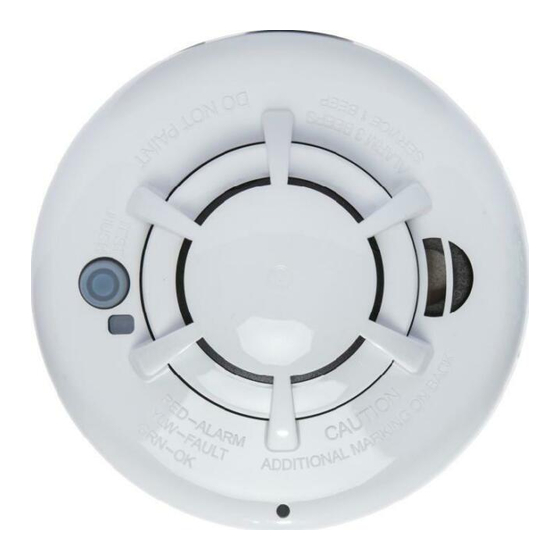
Wireless Smoke Heat Alarm
Installation Guide
ATTENTION: This manual should be read prior to use and retained for
further information.
GENERAL INFORMATION
The Wireless Smoke Heat Alarm is a 3xAAA battery powered wireless
detector intended for use with a compatible wireless alarm system. The
detector has a built-in wireless transmitter, which communicates with the
control panel. When smoke is detected, the alarm sounds a loud local alarm
and the built-in transmitter sends a signal to the control panel. The Wireless
Smoke Heat Alarm contains an integrated fixed 41°F temperature freeze
sensor that will send a warning signal based on temperature detected. This
detector is designed to provide protection with 70-foot spacing capability.
The detector can send alarm, tamper and battery condition messages to
the system's receiver. Refer to the wireless system's instruction for the
maximum number of transmitters that can be supported.
CONTENTS OF BOX:
• Wireless Smoke Heat Alarm with base
• Installation guide (APD0601)
• Pack of screws and anchors
• Labels or decals as appropriate
• 3 AAA PC2400 Duracell Procell batteries (1.5V 1100mAh) or 3 AAA
Energizer E92 batteries (1.5V 1100mAh)
The Wireless Smoke Heat Alarm contains a sounder which generates the
ANSI S3.41 temporal 3 pattern in an alarm condition. In alarm, a message
is also sent to the control panel and the detector's ID is displayed at the
console. During an alarm condition, pressing the detector's hush button
will silence the sounder (see table below). The mounting base installation
is simplified by the incorporation of features compatible for both drywall
fasteners (not supplied) and other methods.
Tricolored LED (red, yellow, green) and a sounder on the detector provide
local visual and audible indication of the detector's status as listed in Table
1.
During initial power-up the LED blinks alternately red, yellow then green. It
takes about 8 seconds for the detector to stabilize.
After power-up has completed and the detector is functioning normally, the
green LED blinks once every 12 seconds.
Detector Trouble: When the detector has a general fault, the yellow LED
blinks once every four seconds and there is a chirp every 48 seconds. After
12 hours the panel will display a loss of supervision message.
Advertisement
Table of Contents

Related Manuals for Apollo 51000-357


Summary of Contents for Apollo 51000-357
- Page 1 51000-355 / 51000-357 • Installation guide (APD0601) • Pack of screws and anchors Wireless Smoke Heat Alarm • Labels or decals as appropriate • 3 AAA PC2400 Duracell Procell batteries (1.5V 1100mAh) or 3 AAA Installation Guide Energizer E92 batteries (1.5V 1100mAh) The Wireless Smoke Heat Alarm contains a sounder which generates the ANSI S3.41 temporal 3 pattern in an alarm condition.
- Page 2 Detector Dirty Feature: When the detector has been contaminated, the Sounder yellow LED blinks once every 8 seconds and there is a chirp every 48 Status LEDs (do not pulse the sounder seconds. Refer to MAINTENANCE section for cleaning your alarm. After 12 Normal Green flash every 12 and LED concurrently)
- Page 3 relative to the stairway so as to intercept smoke coming from a fi re in the uring initial power-up the LED blinks alternately red, yellow then green. the transmitter sends a low battery message to the control panel, which akes about 8 seconds for the detector to stabilize. basement before the smoke enters the stairway.
- Page 4 every 12 seconds to indicate normal operation. If the batteries are not room room the compartment. If the batteries are incorrectly inserted please remove - In or below a cupboard CONSTANT EXPOSURES TO HIGH OR LOW TEMPERATURES OR installed correctly, the detector will not operate and the batteries may be gently with a non-conductive tool and correctly reinsert.
- Page 5 screws are at the elbow of the screw slots and secure. alarm. The outside of the alarm can be wiped with a damp cloth. After cleaning, reinstall and test your alarm by using the test button. If 2. Fit the detector inside the base by aligning it over the base as shown cleaning does not restore the alarm to normal operation the alarm should (detector’s alignment notch should be slightly offset from mounting base be replaced.
- Page 6 MAINTENANCE • Studies have shown that smoke and heat alarms may not awaken all sleeping individuals, and that it is the responsibility of individuals in the TEST ONCE A WEEK. household that are capable of assisting others to provide assistance to WARNING! USE ONLY BATTERIES SPECIFIED.
- Page 7 IF THE ALARM SOUNDS a Class B digital device, pursuant to Part 15 of FCC Rules. These limits are designed to provide reasonable protection against harmful interference in • If the smoke alarm sounds, get out and stay out. Never go back inside a residential installation.
- Page 8 51000-355 / 51000-357 This reprinted material is not the complete and official position of the National Fire Protection Association, on the referenced subject which is Détecteur de chaleur et represented only by the standard in its entirety.) (National Fire Alarm Code® and NFPA 72 ®...
- Page 9 envoyé aussi au panneau de commande et l’ID du détecteur s’affiche Sonde sur la console. En cas de déclenchement d’une alarme, appuyez sur le État (n'appuyez pas simultanément sur bouton de silence du détecteur pour arrêter la sonde (voir le tableau la sonde et la DEL) ci-dessous).
- Page 10 second 1. Remove the detector from its mounting base by twisting the detector Green fl ash every Normal counterclockwise. Remove and dispose of the batteries according to your 12 seconds Freeze 3 yellow fl ashes local regulations. Warning every 4 seconds Red fl...
- Page 11 6. Test the detector (as described later). 6. Test the detector (as described later). dans cette zone the ceiling surface, and begins to bank down from the ceiling. The corner where the ceiling and wall meet is an air space into which the smoke could CONSTANT EXPOSURES TO HIGH OR LOW TEMPERATURES OR CONSTANT EXPOSURES TO HIGH OR LOW TEMPERATURES OR have diffi...
- Page 12 NFPA 72: NATIONAL FIRE ALARM AND SIGNALING CODE. still fails to activate, return for repair. damaged. If the detector does not power-up, check for correct batteries installation and for a fully charged batteries Cave MOUNTING THE DETECTOR MAINTENANCE Fig 4. Un détecteur installé à chaque étage 6.
- Page 13 Appuyez et maintenez le bouton de test pendant au moins 5 secondes. Le est capable de protéger environ la moitié des occupants des incendies potentiellement panneau d’alarme se déclenche puis le détecteur se met en alerte. La sonde émet mortels. Les victimes sont souvent proches de l’incendie, trop âgées ou trop jeunes, la séquence temporelle 3 et la DEL rouge clignote.
- Page 14 intervalle peut être de seulement 1 ou 2 minutes. La planification et la pratique des • Dimensions : Ø 125 mm x hauteur 63 mm (Ø 5 po x hauteur 2,5 po) conditions d’incendie avec un accent sur l’évacuation rapide de l’habitation sont • Poids (piles incluses) : 243 g oz (8,57) importantes.
- Page 15 • Réorientez ou déplacez l’antenne de réception. le parcours du signal a été récemment vérifié au cours d’un test hebdomadaire. Un blocage peut se produire si un objet métallique a été déplacé dans le parcours du • Augmentez la distance qui sépare l’équipement du récepteur •...
- Page 16 Apollo America 25 Corporate Drive Auburn Hills, MI 48326 248-332-3900 Phone 888-332-2241 Tech Support www.apollo-fire.com...
Need help?
Do you have a question about the 51000-357 and is the answer not in the manual?
Questions and answers
Alarm still beats after disconnecting and removing batteries. Ho who you stop it.
To stop the alarm on an Apollo 51000-357 after disconnecting and removing the batteries, clean the alarm using compressed air or a vacuum cleaner hose by blowing or vacuuming through the openings around its perimeter. Wipe the outside with a damp cloth. After cleaning, reinstall the alarm and test it using the test button. If the alarm does not return to normal operation, it may need further maintenance or replacement.
This answer is automatically generated