Advertisement
Quick Links
Technical Data
Supply voltage
17–28V DC
Protocol
5-9V
Quiescent current
2.5mA
Alarm current
4.2mA
Switch-on surge current 9mA (peak) for 85ms
Power-up time
4 seconds
Remote output characteristics
(5mA Maximum)
Fire alarm threshold Analogue value 55 returned after 10Hz flame
flicker for 1.5 seconds
Operating range 25m for 0.1m² n-heptane fire
(EN54-10, Class 1)
Operating temperature –40°C to +70°C (no condensation or icing)
Storage temperature –40°C to +70°C
Relative humidity 0-95% (no condensation)
IP rating
66
Housing material white polycarbonate
V-0 rated to UL94
Dimensions 100mm diameter
40mm height, 48mm in base
Weight 150g detector, 210g in base
Additional Equipment
Portable flame detector test unit
Part no. 29600-226
Adjusted Mounting Bracket
Part no. 29600-458
© Apollo Fire Detectors Limited 2010,
36 Brookside Road, Havant, Hants, PO9 1JR, UK
Tel +44 (0) 23 9249 2412 Fax +44 (0) 23 9249 2754
www.apollo-fire.co.uk
PP2331/2010/Issue 4
connects to positive through 4.5KΩ
8
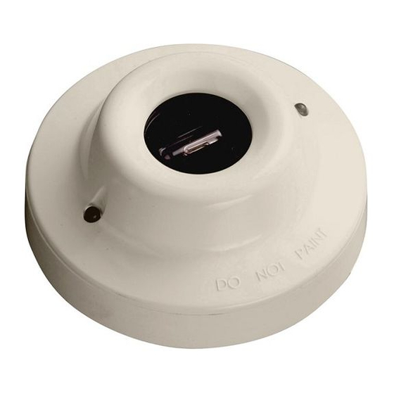
Intelligent Base Mounted IR
Installation & Maintenance Guide
General
The Intelligent Base Mounted Triple Infra-red (IR
designed for use where open flaming fires may be expected. It is sensitive to low-frequency,
flickering infra-red radiation emitted by flames during combustion. False alarms due to such
factors as flickering sunlight are avoided by a combination of filters and signal processing
techniques. This product is not compatable with the 45681-321 isolator base.
Response to flames
In quiescent condition, i.e., in the absence of a flame, the detector returns an analogue
value of 25. When a flame is visible, the detector signals an alarm by increasing the ana-
logue value returned to 55, usually within 1.5 seconds. The analogue value may continue to
rise until it reaches a pre-set maximum of 64.
In the alarm state the IR
Flame Detector latches for 20 seconds, with the analogue value
³
decreasing to 25 once the flame is no longer detected.
Electrical considerations
The IR
Flame Detector is loop powered and needs no external supply. It is connected to a
³
control panel using either the XP95
or Discovery
®
may be connected to the flame detector.
Sensor window contamination
It is important to keep the sensor window clean and checks should be carried out at
regular intervals–determined locally according to the type and degree of contamination
encountered–to ensure optimal performance of the flame detector. Although flames can
be detected when the window is contaminated, there may be a reduction of sensitivity as
shown in the table overleaf.
It is recommended that the IR³ Flame Detector be disabled when the window is being
cleaned.
Flame Detector,
³
) Flame Detector, part no 55000-024, is
3
protocol. A remote LED alarm indicator
®
1
Advertisement

Subscribe to Our Youtube Channel
Related Manuals for Apollo 55000-024


Summary of Contents for Apollo 55000-024
- Page 1 General The Intelligent Base Mounted Triple Infra-red (IR ) Flame Detector, part no 55000-024, is designed for use where open flaming fires may be expected. It is sensitive to low-frequency, flickering infra-red radiation emitted by flames during combustion. False alarms due to such factors as flickering sunlight are avoided by a combination of filters and signal processing techniques.
- Page 2 Functional testing When polled by a compatible panel or test set, the IR Flame Detector, in quiescent condi- ³ tion, should return an analogue value of 25 and input bits set to ‘0’. Contaminant Typical percentage of normal response When output bit 2 is set to logic 1 on two or more consecutive pollings, the red LED on the flame detector will illuminate.
- Page 3 R– From control panel To next device EARTH Width Length © Apollo Fire Detectors Limited 1997-2007/RHD/TP © Apollo Fire Detectors Limited 2000-2005/RHD Fig 4 IR Flame Detector base connections ³ Fig 1 Calculation of distance from detector to flame Terminal Descriptions...
- Page 4 Plan View 10m Dia. 20m Dia. 30m Dia. 40m Dia. © Apollo Fire Detectors Limited 2009/TP Fig 2 Ceiling mounting example The IR Flame Detector has an angle of view of approximately 90°, as shown in the diagram ³ below.
Need help?
Do you have a question about the 55000-024 and is the answer not in the manual?
Questions and answers