Advertisement
Available languages
Available languages
Quick Links
User Manual
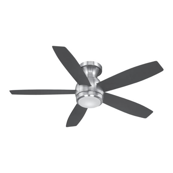
1.3 m (52 in.)
LED Lighted Ceiling Fan
MODEL: 20543
ITM./ART. 4751611
120V 60Hz, MADE IN CHINA
Customer Assistance
1-866-885-4649
Contact a qualified electrician or call the Customer Care Service Team at 1-866-885-4649
1
Customer Service hours of operation are 9:00AM-5:00PM EST -Monday-Friday
Advertisement

Related Manuals for GE 20543


Summary of Contents for GE 20543
- Page 1 User Manual 1.3 m (52 in.) LED Lighted Ceiling Fan MODEL: 20543 ITM./ART. 4751611 120V 60Hz, MADE IN CHINA Customer Assistance 1-866-885-4649 Contact a qualified electrician or call the Customer Care Service Team at 1-866-885-4649 Customer Service hours of operation are 9:00AM-5:00PM EST -Monday-Friday...
- Page 2 Safety Rules 1. To reduce the risk of electric shock, insure electricity has WARNING: to reduce the risk of fire, electric shock or personal been turned off at the circuit breaker or fuse box before injury, mount fan to outlet box beginning.
- Page 3 Basic Guidelines For Working With Electricity 1. Before working on a circuit, go to the main service panel and remove the fuse or trip the breaker that controls that circuit. 2. Tape a sign to the panel warning others to leave the circuit alone while you work.
- Page 4 To Begin / Tools Needed (Not Supplied) REQUIRED Flathead Phillips Screwdriver Safety Glasses Screwdriver (4" recommended) Pliers Wire Cutters Electrical Tape Step Ladder Wire Strippers Soft Cloth...
-
Page 5: Table Of Contents
Hardware Included Carefully unpack and identify each part to make sure you ATTENTION: parts are not to scale. have everything ready for installation. Lay out each part on a clean flat area such as a table or floor. Check to make sure you have the following: Hardware Bag Remote Control... - Page 6 Package Contents Carefully unpack and identify each part to make sure you ATTENTION: parts are not to scale. have everything ready for installation. Lay out each part on a clean flat area such as a table or floor. Check to make sure you have the following: Functional Fasteners PART...
-
Page 7: Receiver
Fan Installation Drawing WARNING: review important safety instructions before installation. Outlet Box (Not Provided) Star Washer Wood Screw (Long) Mounting Bracket Flat Washer Black Wire Spring Washer Mounting Screw Receiver Ground Wire from Mounting Bracket Plastic Wire Nut Antenna Wire Neutral White Wire White Wire Ground Wire from the Fan Motor Assembly... -
Page 8: Mounting Screw
Fan Installation INSTALLING THE MOUNTING BRACKET 1. Use metal outlet box (sold separately) 2. Install mounting bracket (Q) to the suitable for fan support. Secure outlet box outlet box in ceiling using the mounting directly to the building structure using wood screws provided with the outlet box (two screws (A) and star washers (C). -
Page 9: Spring Washer
Fan Installation SECURING FAN TO SECONDARY SUPPORT SYSTEM Spring Wood Safety washer(D) Safety screw cable cable Safety Flat cable washer(E) Drive a wood screw (A) and spring washer (D) and flat washer (E) into the side of the brace that holds the outlet box. Leave the 3 mm (1/8 inch) of space between the support brace and washer. -
Page 10: Plastic Wire Nut
Fan Installation MAKING THE ELECTRICAL CONNECTIONS WARNING: to avoid possible electric shock, be sure electricity is turned off at the main fuse box before wiring. Motor to receiver electrical connections: Connect the black wire from the fan to black wire marked “TO MOTOR L” from NOTE: fan must be installed at the receiver. -
Page 11: Mounting Plate Screw
Fan Installation ATTACHING THE FAN BLADES NOTE: before starting installation, disconnect the power by turning off the circuit breaker or removing the fuse at fuse box. Turning power off using the fan switch may not be sufficient to prevent electric shock. Insert the blade (P) through the slot in the bottom band, align the holes in the blade (P) and the bracket, secure with the blade... -
Page 12: Transmitter
Operation Instructions 3. Install two 1.5-volt AAA batteries (K) provided in the remote control bag. 2. “ O " and " I " dip switch: 1. "Sync" switch: Note : See " REMOTE CONTROL For this fan, the switch should To prevent damage to transmitter (J), remove the PAIRING INSTRUCTIONS"... - Page 13 Operation Instructions 10. Warm weather - (Switch to the left - 11. Cool weather - (Switch to the right - 12. Select a location to install your Counterclockwise direction) A downward Clockwise direction) An upward air flow Transmitter holder (L). Attach the air flow creates a cooling effect as shown.
- Page 14 Remote Control Pairing Instructions REMOTE CONTROL PAIRING INSTRUCTIONS Important Note : By default, every fan has been pre-programmed at the factory and should be fully functional once installation is completed. There is no need to perform the paring process. Should you find the fan or remote control not working or not fully functional after installation or during use, pairing of the remote control can be done by following the below simple procedures.
- Page 15 Blade Balancing The following procedure should correct most fan wobble. Check after each step. Check that all blade and blade bracket screws are secure. Most fan wobble problems are caused when blade levels are unequal. Check this level by selecting a point on the ceiling above the tip of one of the blades.
- Page 16 Blade Balancing The balancing kit should only be used if there is an unacceptable amount of fan wobble after completing all the steps in the user manual under “Fan Blades Assembly.” 1. Turn the fan on and set the speed control setting to a speed at which the wobble is the greatest.
- Page 17 Safety Instructions PRODUCT MAINTENANCE WARNING: make sure the power is off at the electrical panel box before you attempt any repairs. Refer Here are some suggestions to help you maintain your fan. to the section “Making Electrical Connections.” Because of the fan’s natural movement, some connections may become loose.
- Page 18 Manuel de l'utilisateur 1,3 m (52 po) Ventilateur de plafond à lumières DEL MODÈLE : 20543 ITM./ART. 4751611 120 V 60 Hz, FABRIQUÉ EN CHINE Service à la clientèle 1-866-885-4649 Veuillez joindre un maître électricien ou téléphoner à l’équipe du service à la clientèle au 1-866-885-4649...
- Page 19 Consignes de sécurité 1. Afin de réduire le risque de décharge électrique, vous assurer que AVERTISSEMENT : Afin de réduire le risque d’incendie, de décharge l’alimentation électrique est fermée à partir du disjoncteur ou de la électrique ou de blessure boîte à...
- Page 20 Lignes directrices pour le travaux électriques 1. Avant d’entreprendre des travaux sur des circuits électriques, aller au panneau électrique principal et retirer le fusible ou déclencher le disjoncteur responsable du circuit. 2. Poser une affiche sur le panneau afin d’éviter que les gens travaillent ou touchent aux circuits électriques pendant l’installation.
- Page 21 Pour commencer / outils requis (non inclus) OUTILS REQUIS Tournevis à Tournevis à tête Lunettes de sécurité tête plate cruciforme (4 po. recommandé) Pince Coupe-câble Ruban isolant Escabeau Outil à dénuder Chiffon doux...
- Page 22 Quincaillerie incluse Déballer soigneusement chaque pièce et les identifier afin MISE EN GARDE : les pièces ne sont pas à l'échelle. de vous assurer que tous les éléments sont présents pour l’installation. Disposer les pièces sur une surface plane et propre comme une table ou un tapis.
- Page 23 Contenu Déballer soigneusement chaque pièce et les identifier afin MISE EN GARDE : les pièces ne sont pas à l'échelle. de vous assurer que tous les éléments sont présents pour l’installation. Disposer les pièces sur une surface plane et propre comme une table ou un tapis. Vous assurer d’avoir les éléments suivants : Attaches fonctionnelles Pièce...
- Page 24 Diagramme d'installation du ventilateur AVERTISSEMENT : réviser les instructions de sécurité avant de procéder à l’installation. Boîte de sortie (non incluse) Rondelle étoile Longue vis en bois Support de fixation Rondelle plate Câble noir Rondelle élastique Vis de montage Récepteur Câble de mise à...
- Page 25 Installation du ventilateur INSTALLER LE SUPPORT DE FIXATION 1. Utiliser une boîte de sortie en métal (vendue 2. Poser le support de fixation (Q) à la boîte de séparément) apte à soutenir un ventilateur. sortie au plafond avec les vis de fixation fournies Fixer la boîte de sortie directement à...
- Page 26 Installation du ventilateur FIXER LE VENTILATEUR AU SYSTÈME DE SOUTIEN SECONDAIRE Rondelle à Câble de Vis à ressort (D) sécurité Câble de bois (A) Câble de sécurité Rondelle sécurité plate (E) Visser une vis à bois (A) et poser une rondelle à ressort (D) et une rondelle plate (E) dans le contrevent qui soutien la boîte de sortie. Laisser un espace de 3 mm (1/8 po) entre le contrevent de soutien et la rondelle.
- Page 27 Installation du ventilateur BRANCHEMENTS ÉLECTRIQUES AVERTISSEMENT : Afin d’éviter la possibilité de décharge électrique, vous assurer que l’alimentation Connexion électrique du moteur au récepteur : connecter le électrique est fermée à partir de la câble noir du ventilateur au câble noir indiqué « TO MOTOR L » boîte à...
- Page 28 Installation du ventilateur FIXER LES PALES REMARQUE : Avant de procéder à l’installation, débrancher l’alimentation électrique en fermant le disjoncteur ou en retirant le fusible de la boîte à fusibles. Simplement fermer l’alimentation électrique à partir de l’interrupteur du ventilateur pourrait être insuffisant pour prévenir une décharge électrique.
- Page 29 Fonctionnement 3. Installer deux piles AAA de 1,5 volt (K) fournies dans le sac de la télécommande. 1. Touche de synchronisation : 2. Interrupteurs « O » et « I » : Remarque : Voir la section « INSTRUCTIONS Pour ce ventilateur, l’interrupteur Afin d’éviter d’endommager le transmetteur (J), enlever POUR JUMELER LA TÉLÉCOMMANDE »...
- Page 30 Fonctionnement 10. Temps chaud - (interrupteur à gauche 11. Temps frais - (interrupteur à droite Rotation 12. Choisir un emplacement pour installer Rotation dans le sens contraire des aiguilles dans le sens des aiguilles d’une montre). L’air le support d’émetteur (L). Fixer le support d’une montre).
- Page 31 Instructions pour jumeler la télécommande INSTRUCTIONS POUR JUMELER LA TÉLÉCOMMANDE Important : Par défaut, tous les ventilateurs sont préprogrammés à l’usine et devraient être fonctionnels une fois l’installation terminée. Le processus de jumelage n’est pas nécessaire. Si un ventilateur ou une télécommande ne fonctionne pas ou n’est pas entièrement fonctionnel après l’installation complète ou pendant son usage, vous pouvez jumeler la télécommande en suivant le processus décrit ci-dessous.
- Page 32 Équilibrage des pales Ce procédé devrait corriger la plupart des déséquilibres. Vérifier suite à chaque étape. Vous assurer que chaque pale et que les vis du support de fixation des pales sont bien fixées. Les problèmes de déséquilibre sont causés quand les niveaux des pales sont inégaux.
- Page 33 Équilibrage des pales Utiliser seulement la trousse d’équilibrage si le ventilateur de plafond oscille excessivement et que vous avez effectué toutes les étapes notées dans le manuel de l’utilisateur sous la rubrique « Fixer les pales ». 1. Allumer le ventilateur et le faire fonctionner à la vitesse où...
- Page 34 Consignes de sécurité ENTRETIEN DU PRODUIT AVERTISSEMENT : vous assurer que l’alimentation électrique Quelques suggestions pour bien entretenir votre ventilateur. est fermée à partir du panneau électrique avant d’entreprendre À cause du mouvement naturel du ventilateur, il se peut qu’il des réparations.