Table of Contents
Advertisement
Quick Links
INSTRUCTION
EN
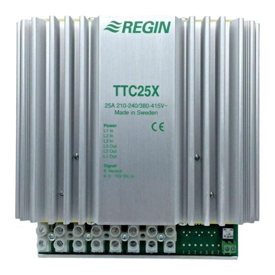
TTC25X
i
Read this instruction before installation
and wiring of the product
Consult documentation in all cases where this symbol
is used, in order to find out the nature of the potential
hazards and any actions to be taken
Triac controller for proportional control of
electric heating
TTC25X is a proportional, 3-phase electric heating controller with
automatic voltage adjustment. The controller operates through step-
less, time-proportional control, where the relationship between the
on-time and off-time is based on the current heat demand.
The controller can control both symmetrical Y-connected 3-phase
heaters and symmetrical or asymmetrical Delta-connected heaters.
TTC25X is only intended for control of electric heating. The control
principle makes it unsuitable for control of motors or lighting.
The controller is intended for DIN-rail mounting.
Technical data
Supply voltage
210...255 / 380...415 V AC 3-phase,
50...60 Hz with automatic voltage adaptation.
Max. current: 25 A/phase.
Max. load
3300 W/phase at 230 V line voltage (25 A)
5750 W/phase at 400 V line voltage (25 A)
Min. load
530 W/phase at 230 V line voltage (4 A)
920 W/phase at 400 V line voltage (4 A)
Protection class
IP20
Ambient temp.
0...40°C, non-condensing
Mount TTC25X on a DIN-rail in a cabinet or other casing.
Mount the controller vertically with the text right side up.
NOTE: At full power, TTC25X will emit approx. 45 W of excess
heat which must be properly dissipated!
Wiring
Connect the supply voltage to the terminals L1in, L2in and L3in.
L1 L2 L3 L3 L2 L1
1 1
3
Figure 1: Wiring of supply voltage and load
NOTE: The controller must be grounded and the supply
voltage must be interlocked via a high temperature limit switch!
Load
Use terminals L1out, L2out and L3out.
Resistive 3-phase heater without neutral connection.
Control signal (figure 2)
Use terminals 8 and 9.
Terminal 8 = Signal neutral.
Terminal 9 = 0...10 V DC.
0 V input will give 0 % output and 10 V input will give 100 % output.
TTC25X
Figure 2: Wiring of control signal
Settings
CT
Control principle
•
TTC25X pulses the entire load On-Off.
•
The controller will adjust the mean power output to the current
power demand by proportionally adjusting the On-time and Off-
time ratio.
•
The pulse period (= the total sum of the On-time and Off-time) is
settable 6...60 seconds by using the potentiometer.
•
TTC25X uses zero phase-angle firing to eliminate radio frequen-
8 9
cy interference.
Start-up and fault finding
1.
Begin by switching off the supply voltage. Next, ensure that all
wiring has been performed correctly.
2.
Measure the resistance between terminals L1out - L2out,
L1out - L3out and L2out -L3out:
At 230 V line voltage: 10.6 Ω <R <66.4 Ω.
At 400 V line voltage: 18.4 Ω <R <115 Ω.
3.
Switch on the supply voltage and set the control signal to 10 V
DC. The LED should be continuously on. Set the control signal
to 0 V DC. The LED should be continuously off.
4.
At an intermediate position the pulsing of the LED will perfectly
coincide with the controller pulsing current to the heater. The
pulse cycle time is 6...60 seconds depending on the settings of
the CT potentiometer. Use a clamp-on multimeter to ensure cur-
rent is passing to the heater when the LED is lit.
8 9
0...10 V DC in
0
NOTE: Do not leave the input unconnected, since an open
circuit will not give 0 % output, but approx. 50 %. To ensure
a 0 % output with no control signal connected, the input
should be short-circuited.
Pulse period. 6...60 seconds. The sum of one On-period
and one Off-period.
1
Advertisement
Table of Contents

Related Manuals for Regin TTC25X


Summary of Contents for Regin TTC25X
- Page 1 Mount the controller vertically with the text right side up. Settings Pulse period. 6...60 seconds. The sum of one On-period NOTE: At full power, TTC25X will emit approx. 45 W of excess and one Off-period. heat which must be properly dissipated!
- Page 2 Montera regulatorn lodrätt med texten rättvänd. inte ger 0 % utstyrning utan ca. 50 %. För att garantera avstängning då styrsignal ej är ansluten ska ingången OBS: TTC25X avger vid full effekt cirka 45 W förlustvärme som kortslutas. måste kylas bort! Inställningar...
- Page 3 Lysdioden ska vara tänd kontinuerligt. Ställ styrsignalen till 0 V ansteuern. DC. Lysdioden ska vara kontinuerligt släckt. Der TTC25X ist nur für die Regelung von Elektroerhitzern vorgesehen. Das Regelprinzip ist für die Regelung von Motoren oder Beleuchtung I ett mellanläge kommer lysdioden att blinka i takt med att ungeeignet.
- Page 4 Parlamentes und des Rates durch EN 50581:2012. Leistungsbedarf, mittels proportionaler Einschalt- und Auss- chaltzeit, an. Kontaktadresse Le TTC25X est un régulateur de puissance triphasé progressif pour • Der Schaltzyklus (Summe der Ein- und Ausschaltzeiten) ist mit- la commande de chauffage électrique offrant une adaptation automa- Regin Controls Deutschland GmbH, Haynauer Str.
- Page 5 Installation Paramètres Monter le TTC25X sur un rail DIN dans une armoire ou un autre Période de répétition des impulsions. 6...60 secondes. Directive basse tension (BT) coffret. La somme d’un cycle d’impulsions (On/Off) Ce produit répond aux exigences de la directive 2014/35/EU du Monter le régulateur à...
Need help?
Do you have a question about the TTC25X and is the answer not in the manual?
Questions and answers