NXP Semiconductors i.MX 8QuadXPlus Hardware User's Manual
Mek board
Hide thumbs
Also See for i.MX 8QuadXPlus:
- Quick start manual (15 pages) ,
- Instruction manual (66 pages) ,
- Quick start manual (31 pages)
Table of Contents
Advertisement
Quick Links
NXP Semiconductors
User's Guide
i.MX 8QuadXPlus MEK Board Hardware User's
Guide
1. Introduction
This document is the Hardware User's Guide for the
i.MX 8QuadXPlus Multisensory Enablement Kit (MEK)
based on the NXP Semiconductor's i.MX 8QuadXPlus
Applications Processor. This board is fully supported by
NXP Semiconductor. The user guide includes system
setup and debugging, and provides detailed information
on the overall design and usage of the MEK board from a
hardware system perspective.
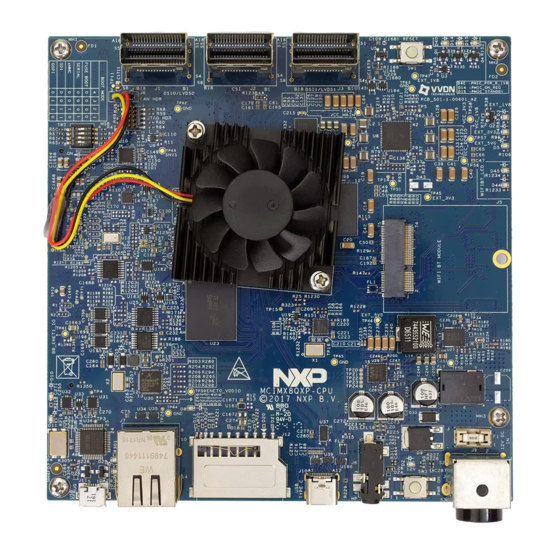
1.1. Board Overview
The MEK board is a platform designed to showcase the
most commonly used features of the i.MX 8QuadXPlus
Applications Processor in a small, low cost package. The
i.MX 8QuadXPlus MEK board is a development board,
which gives the user the option of becoming familiar
with the processor before starting development.
Table
1 lists the features of the i.MX 8QuadXPlus MEK
board.
© 2019 NXP B.V.
Document Number:IMX8QXPMEKHUG
Contents
1.
Introduction ........................................................................ 1
1.1.
Board Overview ...................................................... 1
1.2.
MEK Kit contents .................................................... 2
1.3.
Board revision history ............................................. 3
2.
Specifications ..................................................................... 4
2.1.
Processor ................................................................. 5
2.2.
Boot mode operations and selections ...................... 6
2.3.
Power tree................................................................ 6
2.4.
LPDDR4 DRAM memory ....................................... 9
2.5.
SD card slot (J12) .................................................... 9
2.6.
eMMC memory (U23) ............................................. 9
2.7.
Ethernet connector (J7) ........................................... 9
2.8.
USB Type-C connector (J10) .................................. 9
2.9.
Audio input/output (J8) ......................................... 10
2.10.
UART connector (J11) .......................................... 10
2.11.
JTAG connector (J4) ............................................. 10
2.12.
M.2 Connector (J5) ............................................... 11
2.13.
(J1,J2,J3) ............................................................................. 11
2.14.
Board to Board connector (J13)............................. 12
2.15.
User interface buttons ............................................ 12
2.16.
User Interface LEDs .............................................. 13
2.17.
Sensors .................................................................. 13
2.17.1
Accelerometer + Magnetometer (U14) .................. 13
2.17.2
Pressure Sensor with Altimetry (U18) ................... 13
2.17.3
Ambient Light Sensor (U17) ................................. 14
2.17.4 Gyroscope (U10) .................................................... 14
2.18.
PCB information ................................................... 15
2.19.
MEK design files ................................................... 15
3.
MEK Accessories ............................................................. 15
4.
Revision History ............................................................... 17
Rev. 1 , 01/2019
Advertisement
Table of Contents

Related Manuals for NXP Semiconductors i.MX 8QuadXPlus


Summary of Contents for NXP Semiconductors i.MX 8QuadXPlus
-
Page 1: Table Of Contents
2.17. Sensors ..............13 2.17.1 Accelerometer + Magnetometer (U14) ....13 Table 1 lists the features of the i.MX 8QuadXPlus MEK 2.17.2 Pressure Sensor with Altimetry (U18) ....13 2.17.3 Ambient Light Sensor (U17) ......... 14 board. -
Page 2: Mek Kit Contents
• AC power cord ( IEC cable assembly with locking system for IEC C14 inlet, US version, 1.83 M) • Worldwide adapter • Mini SAS cable ( IPASS(Mini-SAS), internal cable, 36 CKT 4X W/ Sidebands ) i.MX 8QuadXPlus MEK Board Hardware User's Guide, Rev. 1, 01/2019 NXP Semiconductors... -
Page 3: Board Revision History
The board assembly version will be printed on a label, usually attached to the bottom side. The assembly version will be the letter designation following the schematic revision: 700-29683 REV _. i.MX 8QuadXPlus MEK Board Hardware User's Guide, Rev. 1, 01/2019 NXP Semiconductors... -
Page 4: Specifications
Power Supply CAN ESAI CSI RGMII SPI UART I2C PMIC 4 PIN PF8100 DC-DC / LDO Board to Board Connector for Base Board Figure 1. MCIMX8QXP-MEK block diagram i.MX 8QuadXPlus MEK Board Hardware User's Guide, Rev. 1, 01/2019 NXP Semiconductors... -
Page 5: Processor
The i.MX 8QuadXPlus processors represent NXP Semiconductor’s latest achievement in integrated multimedia-focused products offering high performance processing with a high degree of functional integration, targeted towards the growing market of connected devices. The i.MX 8QuadXPlus processor features NXP’s advanced implementation of the Quad Arm Cortex ®... -
Page 6: Boot Mode Operations And Selections
2.3. Power tree There is a +12 V external wall power supply that needs to be connected to the i.MX 8QuadXPlus MEK board at connector J9. The other powers are generated in the MEK board using PMIC, DC to DC converters and LDOs. - Page 7 4, the developer can get all the voltage supply rails used on the MEK board. When some modules are not working, the developer needs to test whether the voltage of this module is correct. Table 3 lists the power rails on the board. i.MX 8QuadXPlus MEK Board Hardware User's Guide, Rev. 1, 01/2019 NXP Semiconductors...
- Page 8 Codec Sensors Audio Connectors RGMII 2x CAN Status LEDs RS 232 TYPE C Connector ETHERNET Connector Mini SAS ARDUINO MIKRO BUS Connector USB OTG Connector 2.8V/0.7A BASE BOARD i.MX 8QuadXPlus MEK Board Hardware User's Guide, Rev. 1, 01/2019 NXP Semiconductors...
-
Page 9: Lpddr4 Dram Memory
Figure 4. Power tree diagram 2.4. LPDDR4 DRAM memory The i.MX 8QuadXPlus MEK board has one 768 Meg × 32 (4 channels × 16 I/O) LPDDR4 SDRAM chip (MT53B768M32D4DT-062 AIT:B) for a total of 3 GB RAM memory. In the physical layout, the LPDDR4 chip is placed on the TOP side, the data traces are not necessarily connected to the LPDDR4 chips in sequential order, but for ease of routing, are connected as best determined by the layout and other critical traces. -
Page 10: Audio Input/Output (J8)
Specifications 2.9. Audio input/output (J8) i.MX 8QuadXPlus MEK board includes one Headphone + Mic connector (J8). J8 is a 3.5 mm audio jack with AHJ pin out. (Rev.D uses AHJ, but previous versions (up to C2) used OMTP pin out). -
Page 11: Connector (J5)
M.2 form factor. 2.13. MIPI- CSI and MIPI-DSI/LVDS connectors (J1,J2,J3) The i.MX 8QuadXPlus processor supports dual MIPI-DSI/LVDS and single MIPI-CSI. The connectors are designed to support camera and display daughter cards developed by NXP. The connectors are as... -
Page 12: Board To Board Connector (J13)
In the ON state, holding the RESET button (SW1) will force to reset the power rails except the VDD_SNVS on the i.MX 8QuadXPlus MEK board. The reset signal from SW1 is connected to the WDI pin of the PMIC. Once the button is pressed, the PMIC will turn off the powers and generate a POR signal to the processor and the peripherals. -
Page 13: User Interface Leds
Table 5. Status Indication LEDs DESCRIPTION Processor RESET status ON : i.MX 8QuadXPlus is in Reset State , OFF : i.MX 8QuadXPlus is in Active State SCU PMIC ON request ON : PMIC is ON , OFF : PMIC is OFF... -
Page 14: Ambient Light Sensor (U17)
2.17.4 Gyroscope (U10) The Gyroscope IC, FXAS21002C from NXP Semiconductors, is a small, low-power, yaw, pitch, and roll angular rate gyroscope with 16 bit ADC resolution. The full-scale range is adjustable from ±250°/s to ±2000°/s. -
Page 15: Pcb Information
MEK Accessories 2.18. PCB information The overall dimensions of the i.MX 8QuadXPlus MEK board PCB are shown in Figure 2. The MEK board is made with standard 8-layer technology. The material used is TU872-SLK Sp, and the PCB stack-up information is shown in Table Table 6. - Page 16 MIPI-CSI interface camera kit based https://www.nxp.com/part/ on OmniVision chipset OV5640 MINISASTOCSI IMX-LVDS-HDMI Converts LVDS signal to HDMI https://www.nxp.com/part/ signal IMX-LVDS-HDMI NOTE Contact Marketing or Sales for operational boards i.MX 8QuadXPlus MEK Board Hardware User's Guide, Rev. 1, 01/2019 NXP Semiconductors...
-
Page 17: Revision History
8 summarizes the changes made to this document since the initial release. Table 8. Revision history Revision number Date Substantive changes 11/2018 Initial release. 01/2019 Updates in Section 2.10 i.MX 8QuadXPlus MEK Board Hardware User's Guide, Rev. 1, 01/2019 NXP Semiconductors... - Page 18 Information in this document is provided solely to enable system and software implementers How to Reach Us: to use NXP products. There are no express or implied copyright licenses granted hereunder to Home Page: design or fabricate any integrated circuits based on the information in this document. NXP www.nxp.com/ reserves the right to make changes without further notice to any products herein.
Need help?
Do you have a question about the i.MX 8QuadXPlus and is the answer not in the manual?
Questions and answers