
Related Manuals for NXP Semiconductors i.MX 8ULP


Summary of Contents for NXP Semiconductors i.MX 8ULP
- Page 1 QUICK START GUIDE i.MX 8ULP EVALUATION KIT i.MX 8ULP EVALUATION KIT Based on i.MX8ULP Applications Processor...
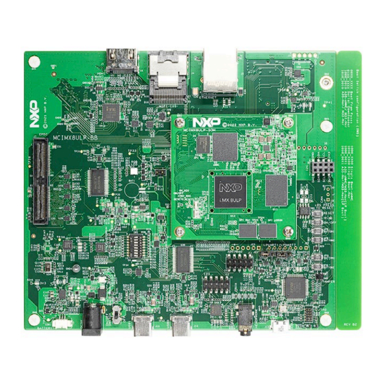
- Page 2 Li-ion Battery Li-ion Battery Connector Connector Connector Connector Power Power S Header S Header Debug Port Debug Port switch switch DC Jack DC Jack USB Type-C USB Type-C Audio Jack Audio Jack Figure 1: Main interfaces of i.MX 8ULP EVK...
- Page 3 8ULP EVALUATION KIT ABOUT THE EVALUATION KIT BASED ON i.MX8ULP The Evaluation Kit (EVK) based on The baseboard provides additional the i.MX 8ULP introduces developers capabilities, including an M.2 Key-E to the i.MX 8ULP applications slot for Wi-Fi/ Bluetooth based on processor.
- Page 4 The following features are available with the EVK based on the i.MX8ULP applica- • Parallel EPDC connector tions processor: • Tamper detect switch • i.MX 8ULP applications processor with • Li-ion battery socket dual 800MHz Arm Cortex -A35 core ®...
-
Page 5: How To Get Started
The evaluation kit is shipped with the items listed in Table 1. Ensure the items are available in the i.MX8ULP Evaluation Kit. ITEM DESCRIPTION SOM board with i.MX 8ULP applications processor, LPDDR4, PMIC, SOM board Octal SPI NOR flash, Octal SPI pSRAM and eMMC Base Board... -
Page 6: Setting Up The System
SETTING UP THE SYSTEM Connect USB Connect Debug Cable Power Supply Connect the micro-B end of the supplied Connect the plug of the 5V power supply USB cable into debug port J17 on the to the DC power jack P1 on the base base board. - Page 7 QUICK START GUIDE i.MX 8ULP EVALUATION KIT BOOT PROCESS FOR LINUX IMAGE Boot Process • Change SW5 on the base board to 1000_0000 (from MSB to LSB, 1-ON and 0-OFF) to boot from the eMMC0, as shown in Figure 2. After the board images are programmed and the boot switches are correctly configured, the system is ready to run.
-
Page 8: Dip Switch Configuration
DIP SWITCH CONFIGURATION Table 3 shows the switch configuration of boot mode for i.MX8ULP EVK. Single Boot-eMMC is chosen as default. BOOT MODE (LSB) (MSB) Boot From Fuses Serial Downloader A35-eMMC/ M33-SPI A35- SPI NOR/ M33-SPI Single Boot-eMMC Single Boot-SPI NOR A35-eMMC/M33-SPI NOR (LP Boot) A35- SPI NOR/M33-SPI... -
Page 9: Button Functions
QUICK START GUIDE i.MX 8ULP EVALUATION KIT BUTTON FUNCTIONS Table 4 shows the functions of the push buttons and switches on the board. ITEM DESCRIPTION Evaluation kit ON/OFF button • Short press and long press will only generate an interrupt. The usage can be defined by upper software. -
Page 10: Additional Information
ADDITIONAL INFORMATION Do more with Accessory Boards RK055HDMIPI4MA0 MINISASTOCSI 5.5-INCH TFT 720 x 1280 PIXELS PANEL MIPI-CSI CAMERA MODULE Use this LCD display for display and Use this MIPI-CSI camera module for machine touchscreen support. vision, video streaming and recording. IMXEBOOKDC5 6-INCH E-PAPER PANEL DAUGHTER CARD Use this panel for e-paper display and touchscreen support. - Page 11 QUICK START GUIDE i.MX 8ULP EVALUATION KIT This device complies with Part 15 of the FCC Rules. Operation is subject to the following two conditions: 1. This device may not cause harmful interference, and 2. This device must accept any interference received, including interference that may cause undesired operation.
-
Page 12: Get Started
GET STARTED Download installation software and documentation at www.nxp.com/iMX8ULPEVK SUPPORT Visit www.nxp.com/support for a list of phone numbers within your region. WARRANTY Visit www.nxp.com/warranty for complete warranty information. www.nxp.com/iMX8ULPEVK NXP and the NXP logo are trademarks of NXP B.V. All other product or service names are the property of their respective owners. The Bluetooth word mark and logos are registered trademarks owned by Bluetooth SIG, Inc.
Need help?
Do you have a question about the i.MX 8ULP and is the answer not in the manual?
Questions and answers