Toshiba RAV-SM562UT-E Installation Manual
Hide thumbs
Also See for RAV-SM562UT-E:
- Service manual/integration (196 pages) ,
- Service manual (4 pages) ,
- Owner's manual (18 pages)
Advertisement
Table of Contents
- 1 Installation Manual
- 2 Table of Contents
- 3 Accessory Parts and Parts to be Procured Locally
- 4 Precautions for Safety
- 5 Selection of Installation Place
- 6 External View
- 7 Drain Piping Work
- 8 Refrigerant Piping and Evacuating
- 9 Air Purge
- 10 Electrical Work
- 11 Wiring Diagram
- 12 Test Run
- 13 Applicable Controls
- 14 Troubleshooting
- Download this manual
AIR CONDITIONER
CLIMATISEUR
(TYPE SPLIT)
KLIMAGERÄT
(SPLIT-TYP)
CONDIZIONATORE D'ARIA
AIRE ACONDICIONADO
AR CONDICIONADO
AIRCONDITIONER
ÊËÉÌÁÔÉÓÔÉÊÏ
<4-Way Air Discharge Cassette Type>/<Type cassette à 4 voies de soufflage>
<4-Wege-Belüftungskassette>/<Tipo a cassetta con scarico d'aria a 4 vie>
<Modelo de casete de distribución de aire de 4 vías>/<Descarga de ar tipo cassete de 4 vias>
<Model voor inbouw in plafond met 4 uitblaasopeningen>/<ÅêñïÞ áÝñá 4-Äéåõèýíóåùí Ôýðïõ ÊáóÝôáò>
Heat Pump Model/Modèle à thermopompe
Geräte mit Heizung/Modello con pompa di riscaldamento
Modelo con bomba de calor/Modelo de bomba térmica
Model met warmtepomp/ÌïíôÝëï ìå Áíôëßá Èåñìüôçôáò
Indoor Unit/Unité intérieure
Raumeinheit/Unità interna
Unidad interior/Unidade interior
Binnenunit/ÅóùôåñéêÞ mïíÜäá
RAV-SM562UT-E
RAV-SM802UT-E
RAV-SM1102UT-E
RAV-SM1402UT-E
RAV-SP1102UT-E
Please read this Installation Manual carefully before installing the Air Conditioner.
• This Manual describes the installation method of the indoor unit.
• For installation of the outdoor unit, follow the Installation Manual
attached to the outdoor unit.
Veuillez lire attentivement ce Manuel d'installation avant d'installer le climatiseur.
• Ce manuel décrit la procédure d'installation de l'unité intérieure.
• Pour installer l'unité extérieure, reportez-vous au Manuel d'installation fourni avec
l'unité extérieure.
Bitte lesen Sie dieses Handbuch sorgfältig, bevor Sie mit der Installation des Klimagerätes beginnen.
• In diesem Handbuch wird die Installation der Raumeinheit beschrieben.
• Um die Außeneinheit zu installieren, folgen Sie den Anweisungen in dem Handbuch, das der Außeneinheit beiliegt.
Prima di installare il condizionatore d'aria, leggere con attenzione questo manuale d'installazione.
• Questo manuale descrive il metodo d'installazione dell'unità interna.
• Per l'installazione dell'unità esterna, fare riferimento al manuale d'installazione fornito insieme all'unità esterna.
Lea atentamente este Manual de instalación antes de proceder a la instalación del aparato de aire acondicionado.
• Este manual describe el método de instalación de la unidad interior.
• Para la instalación de la unidad exterior, consulte el Manual de instalación que acompaña a la unidad exterior.
Leia atentamente o presente Manual de Instalação antes de instalar o Ar Condicionado.
• O presente manual descreve o método de instalar a unidade interior.
• Para a instalação de uma unidade exterior, siga o Manual de Instalação que acompanha a unidade exterior.
Lees deze installatiehandleiding zorgvuldig door voordat u de airconditioner gaat installeren.
• Deze installatiemethode beschrijft de installatiemethode van de binnenunit.
• Zie voor de installatie van de buitenunit, de installatiehandleiding bij de buitenunit.
Ðáñáêáëþ äéáâÜóôå ðñïóå÷ôéêÜ ôï Åã÷åéñßäéï ÅãêáôÜóôáóçò ðñéí áðü ôçí åãêáôÜóôáóç ôïõ Êëéìáôéóôéêïý.
• Ôï ðáñüí Åã÷åéñßäéï ðåñéãñÜöåé ôç ìÝèïäï åãêáôÜóôáóçò ôçò åóùôåñéêÞò ìïíÜäáò.
• Ãéá ôçí åãêáôÜóôáóç ôçò åîùôåñéêÞò ìïíÜäáò, áêïëïõèÞóôå ôï Åã÷åéñßäéï ÅãêáôÜóôáóçò ðïõ óõíïäåýåé ôçí åîùôåñéêÞ
ìïíÜäá.
(SPLIT TYPE)
(TIPO SPLIT)
(TIPO SPLIT)
(TIPO SPLIT)
(GESPLITST TYPE)
(ÔÕÐÏÓ SPLIT)
MANUEL D’INSTALLATION
INSTALLATIONS-HANDBUCH
MANUALE DI INSTALLAZIONE
MANUAL DE INSTALACIÓN
MANUAL DE INSTALAÇÃO
INSTALLATIEHANDLEIDING
ÅÃ×ÅÉÑÉÄÉÏ ÅÃÊÁÔÁÓÔÁÓÇÓ
Outdoor Unit/Unité extérieure
Außengerät/Unità esterna
Unidad exterior/Unidade exterior
Buitenunit/ÅîùôåñéêÞ mïíÜäá
RAV-SM562AT-E
RAV-SM802AT-E
RAV-SM1102AT-E
RAV-SM1402AT-E
INSTALLATION MANUAL
SP562AT-E
SP802AT-E
SP1102AT-E
SP1402AT-E
Advertisement
Table of Contents

Related Manuals for Toshiba RAV-SM562UT-E


Summary of Contents for Toshiba RAV-SM562UT-E
-
Page 1: Installation Manual
Modelo con bomba de calor/Modelo de bomba térmica Model met warmtepomp/ÌïíôÝëï ìå Áíôëßá Èåñìüôçôáò Indoor Unit/Unité intérieure Outdoor Unit/Unité extérieure Raumeinheit/Unità interna Außengerät/Unità esterna Unidad interior/Unidade interior Unidad exterior/Unidade exterior Binnenunit/ÅóùôåñéêÞ mïíÜäá Buitenunit/ÅîùôåñéêÞ mïíÜäá RAV-SM562UT-E RAV-SM562AT-E SP562AT-E RAV-SM802UT-E RAV-SM802AT-E SP802AT-E RAV-SM1102UT-E RAV-SM1102AT-E SP1102AT-E RAV-SM1402UT-E... - Page 2 ADOPTION OF NEW REFRIGERANT This Air Conditioner is a new type which adopts a new refrigerant HFC (R410A) instead of the conventional refriger- ant R22 in order to prevent destruction of the ozone layer. UTILISATION DU NOUVEAU REFRIGERANT Ce climatiseur est d’un type inédit qui utilise le nouveau réfrigérant HFC (R410A) au lieu du réfrigérant traditionnel R22, afin d’éviter la destruction de la couche d’ozone.
-
Page 3: Table Of Contents
CONTENTS Accessory parts and Parts to be procured locally ... 1 ELECTRICAL WORK ............. 13 PRECAUTIONS FOR SAFETY ........2 TEST RUN ..............16 SELECTION OF INSTALLATION PLACE ....... 4 APPLICABLE CONTROLS ........... 18 DRAIN PIPING WORK ............. 9 TROUBLESHOOTING ........... 22 REFRIGERANT PIPING AND EVACUATING .... -
Page 4: Accessory Parts And Parts To Be Procured Locally
Connecting pipe (Liquid side) Connecting cable (indoor and outdoor cable) (6.4mm (diam.), Nominal (diam.) 1/4” thick 0.8mm) H07RN-F or 245 IEC66 (1.5mm² or more) RAV-SM562UT-E (9.5mm (diam.), Nominal (diam.) 3/8” thick 0.8mm) Thermal insulation for refrigerant pipe RAV-SM802UT-E, RAV-SM1102UT-E, (10mm or more, thermal insulating foam polyethylene) -
Page 5: Precautions For Safety
PRECAUTIONS FOR SAFETY • Ensure that all Local, National and International regulations are satisfied. • Read this “PRECAUTIONS FOR SAFETY” carefully before Installation. • The precautions described below include the important items regarding safety. Observe them without fail. • After the installation work, perform a trial operation to check for any problem. Follow the Owner’s Manual to explain how to use and maintain the unit to the customer. - Page 6 PRECAUTIONS FOR SAFETY • After unpacking the unit, examine it carefully if there are possible damage. • Do not install in a place that might increase the vibration of the unit. • To avoid personal injury (with sharp edges), be careful when handling parts. •...
-
Page 7: Selection Of Installation Place
SELECTION OF INSTALLATION PLACE WARNING • Install the air conditioner at enough strong place to withstand the weight of the unit. If the strength is not enough, the unit may fall down resulting in injury. • Install the air conditioner at a height 2.5m or more from the floor. If you insert your hands or others directly into the unit while the air conditioner operates, it is dangerous because you may contact with revolving fan or active electricity. - Page 8 SELECTION OF INSTALLATION PLACE Selection of installation place Discharge direction In case of continued operation of the indoor unit under As shown in the following figure, No. of high-humidity conditions as described below, dew may discharge directions can be selected according condense and water may drop.
-
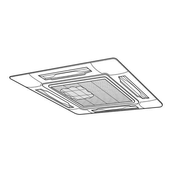
Page 9: External View
External view REQUIREMENT Strictly comply with the following rules to prevent damage of the indoor units and human injury. • Do not put a heavy article on the indoor unit. (Even units are packaged) • Carry in the indoor unit as it is packaged if possible. If carrying in the indoor unit unpacked by necessity, be sure to use buffering cloth, etc. - Page 10 SELECTION OF INSTALLATION PLACE Opening a ceiling and installation of hanging bolts <Treatment of ceiling> The ceiling differs according to structure of building. For details, consult your constructor or interior finish contractor. In the process after the ceiling board has been removed, it is important to reinforce ceiling foundation (frame) and to keep horizontal level of installed ceiling correctly in order to prevent vibration of ceiling board.
- Page 11 REQUIREMENT Installation of remote controller (Sold separately) Before installation of the indoor unit, be sure to remove the cushion for transportation between the For installation of the wired remote controller, follow fan and the bell mouth. Running the unit without the Installation Manual attached with the remote removing the cushion may damage the fan motor.
-
Page 12: Drain Piping Work
DRAIN PIPING WORK Piping/Heat insulating material CAUTION Require the following materials for piping and heat • Following the Installation Manual, insulating at site. perform the drain piping work so that water is properly drained, and apply a Hard vinyl chloride pipe VP25 Piping heat insulation so as not to cause a dew. - Page 13 Connection procedure Check the draining Connect a socket and a hard vinyl chloride pipe. In the test run, check that water drain is properly performed and water does not leak from the • Using adhesive agent for vinyl chloride pipe, connect connecting part of the pipes.
-
Page 14: Refrigerant Piping And Evacuating
REFRIGERANT PIPING AND EVACUATING • Flaring diam. meter size : A (Unit : mm) Refrigerant Piping 1. If the outdoor units are to be mounted on a wall, - 0.4 Outer diam. of copper pipe make sure that the supporting platform is R410A sufficiently strong. -
Page 15: Air Purge
Piping with outdoor unit Open the valve fully • Shape of valve differs according to the outdoor unit. Open the valve of the outdoor unit fully. A 4mm- hexagonal wrench is required for opening the valve. For details of installation, refer to the Installation Manual of the outdoor unit. -
Page 16: Electrical Work
ELECTRICAL WORK WARNING 1. Using the specified cables, ensure to connect the wires, and fix wires securely so that the external tension to the cables do not affect the connecting part of the terminals. Incomplete connection or fixation may cause a fire, etc. 2. - Page 17 Cable connection REQUIREMENT • Be sure to connect the cables matching the terminal numbers. Incorrect connection causes a trouble. • Be sure to pass the cables through the bushing of cabling connection port of the indoor unit. • Keep a margin (Approx. 100mm) on a cable to hang down the electric parts box at servicing, etc. •...
-
Page 18: Wiring Diagram
ELECTRICAL WORK Cabling Remote Controller Cabling 1. Remove a screw and then remove cover of the • Strip off approx. 9mm the cable to be connected. electric parts box. • Non polarity, 2 core cable is used for cabling of the 2. -
Page 19: Test Run
TEST RUN Before test run • Before turning on the power supply, carry out the following procedure. 1) Using 500V-megger, check 1MΩ or more exists between the terminal block 1 to 3 and the earth. If 1MΩ or less is detected, do not run the unit. Do not apply to the remote controller circuit. 2) Check the valve of the outdoor unit being opened fully. - Page 20 In case of wireless remote controller Procedure Description Turn off the power supply of the air conditioner. Remove the adjust corner cap attached with the sensor part from the ceiling panel. To remove it, refer to Installation Manual attached to the ceiling panel. (Be cautious to treat the sensor part because it is connected with wires.) Remove the sensor cover from the adjust corner cap.
-
Page 21: Applicable Controls
APPLICABLE CONTROLS Change of lighting time of filter sign To secure better effect of heating According to the installation condition, the lighting time When it is difficult to obtain satisfactory heating due to of the filter sign (Notification of filter cleaning) can be installation place of the indoor unit or structure of the changed. -
Page 22: Group Control
APPLICABLE CONTROLS Group control Simultaneous twin system If combining with an outdoor unit, ON/OFF operation of two <Twin system> indoor units is simultaneously available for the twin system. Outdoor unit Indoor unit Indoor unit • For wiring procedure and wiring method, follow to the Remote controller “Electric work”... - Page 23 Procedure example Manual address setup procedure While the operation stops, change the setup. (Be sure to stop the operation of the unit.) CODE No. DATA SETTING TEST UNIT No. R.C. TEMP. ON / OFF TIMER SET MODE TIME SWING/FIX VENT FILTER RESET TEST SET CL...
- Page 24 APPLICABLE CONTROLS Procedure Description If there is other indoor unit to be changed, repeat Indoor unit No. before setup change is displayed. procedure to change the setup. UNIT CODE No. When the above setup has finished, push DATA SETTING TEST select the indoor unit No.
-
Page 25: Troubleshooting
TROUBLESHOOTING Confirmation and check When a trouble occurred in the air conditioner, the CODE No. check code and the indoor unit No. appear on the UNIT No. display part of the remote controller. R.C. The check code is only displayed during the operation. If the display disappears, operate the air conditioner according to the following “Confirmation of error Check code... - Page 26 MAINTENANCE Before maintenance, be sure to turn off the leakage breaker. Cleaning of air filter • If is displayed on the remote controller, maintain the air filter. • Clogging of the air filter reduce cooling/heating performance. Cleaning of panel and air filter Suction grille Preparation : 1.
- Page 27 This product is compliant with Directive 2002/95/EC, and cannot be disposed as unsorted municipal waste. Ce produit est conforme à la Directive 2002/95/CE et il ne peut pas être jeté avec les ordures ménagères non triées. Dieses Produkt entspricht der Richtlinie 2002/95/EWG und darf nicht als normaler, unsortierter Hausabfall entsorgt werden.
Need help?
Do you have a question about the RAV-SM562UT-E and is the answer not in the manual?
Questions and answers