Toshiba RAV-SP560AT-E Service Manual
Split type
Hide thumbs
Also See for RAV-SP560AT-E:
- Service manual (248 pages) ,
- Service manual (31 pages) ,
- Service manual (109 pages)
Table of Contents
Advertisement
SERVICE MANUAL/INTEGRATION
RAV-SP560AT-E, RAV-SP800AT-E, RAV-SP1100AT-E, RAV-SP1400AT-E
RAV-SM560AT-E, RAV-SM800AT-E, RAV-SM1100AT-E, RAV-SM1400AT-E
RAV-SM560UT-E, RAV-SM560BT-E, RAV-SM561BT-E, RAV-SM561CT-E,
RAV-SM800UT-E, RAV-SM800BT-E, RAV-SM801BT-E, RAV-SM801CT-E,
RAV-SM1100UT-E, RAV-SM1101CT-E, RAV-SM1101BT-E,
RAV-SM1400UT-E, RAV-SM1401CT-E, RAV-SM1401BT-E
R410A
FILE NO. A03-003F
SPLIT TYPE
OUTDOOR UNIT
<SUPER DIGITAL INVERTER>
<DIGITAL INVERTER>
INDOOR UNIT
<SUPER DIGITAL INVERTER>
RAV-SP1100UT-E
<DIGITAL INVERTER>
PRINTED IN JAPAN, Jun.,2004 ToMo
Advertisement
Table of Contents
Troubleshooting

Related Manuals for Toshiba RAV-SP560AT-E


Summary of Contents for Toshiba RAV-SP560AT-E
-
Page 1: Sdi Combination, Indoor / Outdoor
FILE NO. A03-003F SERVICE MANUAL/INTEGRATION SPLIT TYPE OUTDOOR UNIT <SUPER DIGITAL INVERTER> RAV-SP560AT-E, RAV-SP800AT-E, RAV-SP1100AT-E, RAV-SP1400AT-E <DIGITAL INVERTER> RAV-SM560AT-E, RAV-SM800AT-E, RAV-SM1100AT-E, RAV-SM1400AT-E INDOOR UNIT <SUPER DIGITAL INVERTER> RAV-SP1100UT-E <DIGITAL INVERTER> RAV-SM560UT-E, RAV-SM560BT-E, RAV-SM561BT-E, RAV-SM561CT-E, RAV-SM800UT-E, RAV-SM800BT-E, RAV-SM801BT-E, RAV-SM801CT-E, RAV-SM1100UT-E, RAV-SM1101CT-E, RAV-SM1101BT-E,... -
Page 2: Specification For Concealed Duct Type
∗∗∗∗ Concerning models for RAV-SM KRT-E, and RAV-SM XT-E series, please contact the following company ; Toshiba Carrier (Thailand) Co., Ltd. 144/9 Moo 5, BangKadi Indastrial park, Tivanon Road, Tambol BangKadi, Amphur Muang, Pathumthani 12000, Thailand Tel : +66-2-501-1390 Fax : +66-2-501-1130... -
Page 3: Table Of Contents
CONTENTS 1. SPECIFICATIONS ..........................4 1-1. Indoor Unit ................................4 1-2. Outdoor Unit ..............................10 1-3. Combination Specifications of Indoor Units with Outdoor Units ..............14 1-4. Operation Characteristic Curve ........................17 2. AIR DUCTING WORK ........................24 2-1. Static Pressure Characteristics of Each Model ..................... 24 3. -
Page 4: Specifications
RAV-SM560/800UT-E 1. SPECIFICATIONS 1-1. Indoor Unit 1-1-1. 4-Way Air Discharge Cassette Type RAV-SM560UT-E, RAV-SM800UT-E (A02-014) Model name RAV-SM560UT-E RAV-SM800UT-E Cooling Heating Average Cooling Heating Average Standard capacity (Note 1) (kW) (1.5 – 5.6) (1.5 – 6.3) (2.2 – 8.0) (2.2–9.0) Heating low temp. -
Page 5: Indoor Unit & Remote Controller
RAV-SM1100/1400UT-E RAV-SM1100UT-E, RAV-SM1400UT-E (A03-003) Model name RAV-SM1100UT-E RAV-SM1400UT-E Cooling Heating Average Cooling Heating Average Standard capacity (Note 1) (kW) 10.0 11.2 12.3 14.0 (2.2 – 11.2) (2.2 – 13.0) (3.0 – 13.2) (3.0 – 16.0) Energy consumption effect ratio (Cooling) 2.84 3.22 3.03... - Page 6 RAV-SP1100UT-E RAV-SP1100UT-E (A03-014) Model name RAV-SP1100UT-E Main unit Zinc hot dipping steel plate Appearance Model RBC-U21PG (W)-E Ceiling Panel (Sold separately) Panel color Moon-white (Muncel 2.5GY 9.0/0.5) Height (mm) Main unit Width (mm) Depth (mm) Outer dimension Height (mm) Ceiling panel Width (mm) (Sold separately)
-
Page 7: Concealed Duct Type
RAV-SM560/800BT-E 1-1-2. Concealed Duct Type RAV-SM560BT-E, RAV-SM800BT-E (A02-014) Model name RAV-SM560BT-E RAV-SM800BT-E Cooling Heating Average Cooling Heating Average Standard capacity (Note 1) (kW) (1.5 – 5.6) (1.5 – 6.3) (2.2 – 8.0) (2.2–9.0) Heating low temp. capacity (Note 1) (kW) Energy consumption effect ratio (Cooling) 2.60 [D] 3.27 [C]... - Page 8 RAV-SM561/801BT-E RAV-SM561BT-E, RAV-SM801BT-E (A03-007) Model name RAV-SM561BT-E RAV-SM801BT-E Cooling Heating Average Cooling Heating Average Standard capacity (Note 1) (kW) (1.5 – 5.6) (1.5 – 6.3) (2.2 – 8.0) (2.2 – 9.0) Heating low temp. capacity (Note 1) (kW) Energy consumption effect ratio (Cooling) 2.81 [C] 3.27 [C] 3.04...
- Page 9 RAV-SM1101/1401BT-E RAV-SM1101BT-E, RAV-SM1401BT-E (A03-007) Model name RAV-SM1101BT-E RAV-SM1401BT-E Cooling Heating Average Cooling Heating Average Standard capacity (Note 1) (kW) 10.0 11.2 12.5 14.0 (2.2 – 11.2) (2.2 – 12.5) (3.0 – 13.2) (3.0 – 16.0) Heating low temp. capacity (Note 1) (kW) 11.8 Energy consumption effect ratio (Cooling) 2.81 [C]...
-
Page 10: Outdoor Unit
RAV-SM561/801CT-E 1-1-3. Under Ceiling Type RAV-SM561CT-E, RAV-SM801CT-E (A03-016) Model name RAV-SM561CT-E RAV-SM801CT-E Cooling Heating Average Cooling Heating Average Standard capacity (Note 1) (kW) (1.5 – 5.6) (1.5 – 6.3) (2.2 – 8.0) (2.2 – 9.0) Energy consumption effect ratio (Cooling) 2.75 [D] 3.41 [B] 3.08... - Page 11 RAV-SM1101/1401CT-E RAV-SM1101CT-E, RAV-SM1401CT-E (A03-016) Model name RAV-SM1101CT-E RAV-SM1401CT-E Cooling Heating Average Cooling Heating Average Standard capacity (Note 1) (kW) 10.0 11.2 12.3 14.0 (2.2 – 11.2) (2.2 – 12.5) (3.0 – 13.2) (3.0 – 16.0) Energy consumption effect ratio (Cooling) 2.85 [C] 3.50 [B] 3.18...
- Page 12 RAV-SM560/800AT-E 1-2. Outdoor Unit RAV-SM560AT-E, RAV-SM800AT-E (A02-14) Model name RAV-SM560AT-E RAV-SM800AT-E Appearance Silky shade (Muncel 1Y8.5/0.5) 1 phase 230V (220 – 240V) 50Hz Power supply (Power exclusive to outdoor is required.) Type Hermetic compressor Compressor Motor (kW) Pole 4 poles Refrigerant charged (kg) R410A 0.9...
- Page 13 RAV-SM1100/1400AT-E RAV-SM1100AT-E, RAV-SM1400AT-E (A03-003) Model name RAV-SM1100AT-E RAV-SM1400AT-E Appearance Silky shade (Muncel 1Y8.5/0.5) 1 phase 230V (220 – 240V) 50Hz Power supply (Power exclusive to outdoor is required.) Type Hermetic compressor Compressor Motor (kW) 3.75 Pole 4 poles Refrigerant charged (kg) R410A 2.1 R410A 2.3...
-
Page 14: Combination Specifications Of Indoor Units With Outdoor Units
RAV-SP560/800AT-E RAV-SP560AT-E, RAV-SP800AT-E (A03-14) Model name RAV-SP560AT-E RAV-SP800AT-E Appearance Silky shade (Muncel 1Y8.5/0.5) 1 phase 230V (220 – 240V) 50Hz Power supply (Power exclusive to outdoor is required.) Type Hermetic compressor Compressor Motor (kW) Pole 4 poles Refrigerant charged (kg) R410A 1.5... - Page 15 RAV-SP1100/1400AT-E RAV-SP1100AT-E, RAV--SP1400AT-E (A03-14) Model name RAV-SP1100AT-E RAV-SP1400AT-E Appearance Silky shade (Muncel 1Y8.5/0.5) 1 phase 230V (220 – 240V) 50Hz Power supply (Power exclusive to outdoor is required.) Type Hermetic compressor Compressor Motor (kW) 3.75 Pole 4 poles Refrigerant charged (kg) R410A 2.95 Refrigerant control...
- Page 16 All Models 1-3. Combination Specifications of Indoor Units with Outdoor Units 4-way Air Discharge Cassette type RAV-SM560UT-E, RAV-SM800UT-E, RAV-SP1100UT-E, RAV-SM1400UT-E RAV-SP560AT-E, RAV-SP800AT-E, RAV-SP1100AT-E, RAV-SP1400AT-E Indoor Unit RAV-SM560UT-E RAV-SM800UT-E RAV-SP1100UT-E RAV-SM1400UT-E Outdoor Unit RAV-SP560AT-E RAV-SP800AT-E RAV-SP1100AT-E RAV-SP1400AT-E Cooling Heating Cooling Heating...
-
Page 17: Operation Characteristic Curve
RAV-SM560/800UT-E RAV-SM560/800BT-E 1-4. Operation Characteristic Curve • Operation characteristic curve (A02-014) RAV-SM560UT-E, RAV-SM560BT-E, RAV-SM800UT-E, RAV-SM800BT-E <Cooling> <Heating> SM800UT-E SM800UT-E SM800UT-E SM800BT-E SM800BT-E SM800BT-E SM800UT-E SM800UT-E SM800UT-E SM800BT-E SM800BT-E SM800BT-E SM560UT-E SM560UT-E SM560UT-E SM560BT-E SM560BT-E SM560BT-E SM560UT-E SM560UT-E SM560UT-E SM560BT-EE SM560BT-EE SM560BT-E •... - Page 18 RAV-SM561/801/1101BT-E • Operation characteristic curve (A03-007) RAV-SM561BT-E, RAV-SM801BT-E <Cooling> <Heating> RAV-SM801BT-E RAV-SM801BT-E RAV-SM561BT-E RAV-SM561BT-E • Conditions • Conditions Indoor : DB20˚C Indoor : DB27˚C/WB19˚C Outdoor : DB7˚C/WB6˚C Outdoor : DB35˚C Air flow : High Air flow : High Pipe length : 7.5m Pipe length : 7.5m 220V 220V...
- Page 19 RAV-SM1100/1400UT-E • Operation characteristic curve (A03-003) RAV-SM1100UT-E <Cooling> <Heating> SM1100UT-E SM1100UT-E SM1100UT-E SM1100UT-E • Conditions • Conditions Indoor : DB27˚C/WB19˚C Indoor : DB20˚C Outdoor : DB35˚C Outdoor : DB7˚C/WB6˚C Air flow : High Air flow : High Pipe length : 7.5m Pipe length : 7.5m 230V 230V...
- Page 20 RAV-SP560/800AT-E RAV-SP1100/1400AT-E • Operation characteristic curve (A03-014) RAV-SP560AT-E, RAV-SP800AT-E <Cooling> <Heating> RAV-SP800AT-E RAV-SP800AT-E RAV-SP800AT-E RAV-SP800AT-E RAV-SP560AT-E RAV-SP560AT-E RAV-SP560AT-E RAV-SP560AT-E • Conditions • Conditions Indoor : DB20˚C Indoor : DB27˚C/WB19˚C Outdoor : DB7˚C/WB6˚C Outdoor : DB35˚C Air flow : High Air flow : High Pipe length : 7.5m...
- Page 21 RAV-SP560/800AT-E RAV-SP1100/1400AT-E • Capacity variation ratio according to temperature (A03-014) RAV-SP560AT-E, RAV-SP800AT-E, RAV-SP1100AT-E, RAV-SP1400AT-E <Cooling> <Heating> • Conditions • Conditions Indoor : DB20˚C Indoor : DB27˚C/WB19˚C Indoor air flow : High Indoor air flow : High Pipe length : 7.5m Pipe length : 7.5m...
- Page 22 RAV-SM561/801/1101CT-E • Operation characteristic curve (A03-016) RAV-SM561CT-E, RAV-SM801CT-E <Cooling> <Heating> RAV-SM801CT-E RAV-SM801CT-E RAV-SM801CT-E RAV-SM801CT-E RAV-SM561CT-E RAV-SM561CT-E RAV-SM561CT-E RAV-SM561CT-E RAV-SM561CT-E RAV-SM561CT-E • Conditions • Conditions Indoor : DB20˚C Indoor : DB27˚C/WB19˚C Outdoor : DB7˚C/WB6˚C Outdoor : DB35˚C Air flow : High Air flow : High Pipe length : 7.5m Pipe length : 7.5m...
- Page 23 RAV-SM1401CT-E • Operation characteristic curve (A03-016) RAV-SM1401CT-E <Cooling> <Heating> RAV-SM1401CT-E RAV-SM1401CT-E RAV-SM1401CT-E RAV-SM1401CT-E • Conditions • Conditions Indoor : DB27˚C/WB19˚C Indoor : DB20˚C Outdoor : DB35˚C Outdoor : DB7˚C/WB6˚C Air flow : High Air flow : High Pipe length : 7.5m Pipe length : 7.5m 230V 230V...
-
Page 24: Air Ducting Work
RAV-SM560/800BT-E 2. AIR DUCTING WORK 2-1. Static Pressure Characteristics of Each Model RAV-SM560BT-E, RAV-SM800BT-E (A02-014) Fig. 1 RAV-SM560BT-E 70% (570m³/h) 110% (925m³/h) Standard air volume : 840m³/h Extra High tap Extra High tap High tap High tap Middole tap Middle tap Low tap Low tap 900 925... - Page 25 RAV-SM561/801/1101/1401BT-E RAV-SM561BT-E, RAV-SM801BT-E, RAV-SM1101BT-E, RAV-SM1401BT-E (A03-007) Fig. 1 RAV-SM561BT-E (Round duct) Fig. 3 RAV-SM801BT-E (Round duct) Standard air volume 780m³/h Standard air volume 1140m³/h 1000 1140 1200 1300 Air volume m³/h Air volume m³/h Fig. 2 RAV-SM561BT-E (Square duct) Fig. 4 RAV-SM801BT-E (Square duct) Standard air volume 780m³/h Standard air volume 1140m³/h 1000...
- Page 26 RAV-SM1101/1401BT-E Fig. 5 RAV-SM1101BT-E (Round duct) Fig. 7 RAV-SM1401BT-E (Round duct) Standard air volume 1620m³/h Standard air volume 1980m³/h 1620 1980 1200 2000 1200 1800 2200 2400 Air volume m³/h Air volume m³/h Fig. 6 RAV-SM1101BT-E (Square duct) Fig. 8 RAV-SM1401BT-E (Square duct) Standard air volume 1620m³/h Standard air volume 1980m³/h 1200...
-
Page 27: Construction Views (External Views)
RAV-SM560/800UT-E 3. CONSTRUCTION VIEWS (EXTERNAL VIEWS) 3-1. Indoor Unit 3-1-1. 4-Way Air Discharge Cassette Type RAV-SM560UT-E, RAV-SM800UT-E (A02-014) 860 to 910 Recommended external size Check port ( 450) Check port ( 450) Standing 850 or less Surface Standing under ceiling Cable draw-in port 640 or less Surface... - Page 28 RAV-SM1100/1400UT-E RAV-SP1100UT-E RAV-SM1100UT-E, RAV-SM1400UT-E (A03-003), RAV-SP1100UT-E (A03-014) 860 to 910 Recommended external size Check port ( 450) Check port SM1100UT Ø12.7 Ø15.9 ( 450) SM1400UT Ø12.7 Ø15.9 SP1100UT Ø9.5 Ø15.9 Standing 850 or less Standing 640 or less Ceiling bottom surface Take-in port of pipes Surface under ceiling...
- Page 29 RAV-SM560BT-E 3-1-2. Concealed Duct Type RAV-SM560BT-E (A02-014) 750 ± 7.5 Hanging bolt pitch 2-Ø200 700 Dimension of main unit Discharge port flange 4-M10 Drain up kit Hanging bolt (Sold separately) (Procured locally) For hanging bolt M10 (4-12 x 25 long hole) 780 Ceiling opening size 800 Dimension of main unit 565 Hanging bolt pitch...
- Page 30 RAV-SM561/800/801/1101/1401BT-E RAV-SM561BT-E, RAV-SM800BT-E, RAV-SM801BT-E, RAV-SM1101BT-E, RAV-SM1401BT-E (A03-007) Refrigerant pipe connecting port Drain pipe connecting port (Gas side ØF) for vinyl chloride pipe (Inner dia. 32, VP. 25) Hanging bolt 4-M10 screw Discharge port flange (Arranged locally) N-Ø200 Main unit dimension 800 Hanging bolt pitch B Hanging bolt pitch 700 59 Main unit dimension A...
- Page 31 RAV-SM561/801/1101/1401CT-E 3-1-3. Under Ceiling Type RAV-SM561CT-E, RAV-SM801CT-E, RAV-SM1101CT-E, RAV-SM1401CT-E (A03-016) Upper pipe draw-out port (Knockout hole) Power supply cable take-in port (Knockout) Pipe draw-out port (Knockout hole) Remote controller cable take- in port Drain port VP20 (Knockout hole) (Inner dia. Ø26, hose attached) Refrigerant pipe Left drain size (Liquid side ØC)
-
Page 32: Outdoor Unit
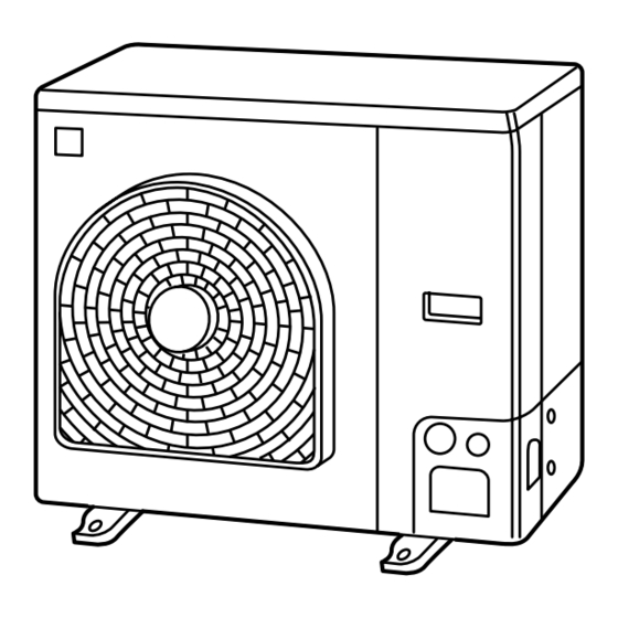
RAV-SM560AT-E 3-2. Outdoor Unit RAV-SM560AT-E (A02-014) Drain hole (2-Ø20 x 88 long hole) Drain hole (Ø25) A legs 115.3 125 B legs Discharge guide mounting hole 115.3 49.5 (4-Ø4 embossing) Discharge guard Valve cover Earth terminal 500 (Fan center dividing) Charge port Protective net mounting hole (2-Ø4 embossing) - Page 33 RAV-SM800AT-E RAV-SP560/800AT-E RAV-SM800AT-E (A02-014), RAV-SP560AT-E, RAV-SP800AT-E (A03-014) Knockout Drain hole (Ø20 x 88 Burring hole) (For draining) Drain hole (Ø25 Burring hole) Installation bolt hole (Ø12 x 17 U-shape holes) Suction Part B port Suction Details of B part Knockout...
- Page 34 RAV-SM1100/1400AT-E RAV-SP1100/1400AT-E RAV-SM1100AT-E, RAV-SM1400AT-E (A03-003), RAV-SP1100AT-E, RAV-SP1400AT-E (A03-014) Knockout(Drain) Drain hole (Ø20 x 88) Suction Drain hole (Ø25) port B legs A legs Suction Knockout(Drain) port Discharge port Refrigerant pipe connecting port (Ø9.5 flare at liquid side) Refrigerant pipe connecting port (Ø15.9 flare at gas side) Mountig bolt hole Mountig bolt hole...
-
Page 35: Systematic Refrigerating Cycle Diagram
RAV-SM560UT-E, RAV-SM560/561BT-E, RAV-SM560KRT-E, RAV-SP560AT-E RAV-SM561/801/1101/1401CT-E, RAV-SM560AT-E 4. SYSTEMATIC REFRIGERATING CYCLE DIAGRAM 4-1. Indoor Unit/Outdoor Unit RAV-SM560UT-E, RAV-SM560BT-E, RAV-SM561BT-E, RAV-SM560KRT-E, RAV-SP560AT-E, RAV-SM561CT-E, RAV-SM801CT-E, RAV-SM1101CT-E, RAV-SM1401CT-E, RAV-SM560AT-E (A02-014, A03-014, A03-016) Indoor unit sensor Air heat exchanger TC sensor Outer diameter of refrigerant pipe Model Gas side ØA... - Page 36 RAV-SM800UT-E, RAV-SM800/801BT-E, RAV-SM800AT-E, RAV-SM800KRT-E, RAV-SP800AT-E RAV-SM800UT-E, RAV-SM800BT-E, RAV-SM801BT-E, RAV-SM800AT-E, RAV-SM800KRT-E, RAV-SP800AT-E (A02-014, A03-007, A03-014) Indoor unit sensor Air heat exchanger TC sensor Outer diameter of refrigerant pipe Gas side ØA Liquid side ØB 15.9mm 9.5mm Refrigerant pipe Refrigerant pipe at liquid side at gas side Outer dia.
- Page 37 SM801BT-E / SM800AT-E, SM800UT-E, RAV-SM1100UT-E SM800BT-E, SM800KRT-E RAV-SM1100AT-E RAV-SM1100UT-E, RAV-SM1100AT-E (A03-003) Indoor unit Distributor TCJ sensor (Strainer incorporated) Outer diameter of refrigerant pipe Strainer Gas side ØA Liquid side ØB Air heat exchanger 15.9mm 9.5mm TC sensor Refrigerant pipe Refrigerant pipe at gas side at liquid side Outer dia.
- Page 38 RAV-SM1400UT-E, RAV-SM1400AT-E, RAV-SM1401BT-E RAV-SM1401CT-E, RAV-SP1400AT-E RAV-SM1400UT-E, RAV-SM1400AT-E, RAV-SM1401BT-E, RAV-SM1401CT-E, RAV-SP1400AT-E Indoor unit Distributor TCJ sensor (Strainer incorporated) Outer diameter of refrigerant pipe Strainer Gas side ØA Liquid side ØB Air heat exchanger 15.9mm 9.5mm TC sensor Refrigerant pipe Refrigerant pipe at gas side at liquid side Outer dia.
- Page 39 RAV-SP560AT-E RAV-SP560AT-E (A03-014) Indoor unit sensor Air heat exchanger TC sensor Outer diameter of refrigerant pipe Gas side ØA Liquid side ØB 12.7mm 6.4mm Refrigerant pipe Refrigerant pipe at gas side at liquid side Outer dia. ØA Outer dia. ØB Min.
- Page 40 RAV-SP800AT-E RAV-SP800AT-E (A03-014) Indoor unit sensor Air heat exchanger TC sensor Outer diameter of refrigerant pipe Gas side ØA Liquid side ØB 15.9mm 9.5mm Refrigerant pipe Refrigerant pipe at gas side at liquid side Outer dia. ØA Outer dia. ØB Min.
- Page 41 RAV-SM1100UT-E, RAV-SM1101BT-E, RAV-SM1101CT-E, RAV-SP1100AT-E RAV-SM1100UT-E, RAV-SM1101BT-E, RAV-SM1101CT-E, RAV-SP1100AT-E (A03-014) Indoor unit Distributor TCJ sensor (Strainer incorporated) Strainer Air heat exchanger TC sensor * The refrigerating cycle of the indoor units differs according to Outer diameter of refrigerant pipe the models to be combined. For the refrigerating cycles of the Gas side ØA Liquid side ØB other indoor units, refer to the corresponding Service Manuals...
- Page 42 RAV-SM1401CT-E RAV-SP1400AT-E RAV-SM1401CT-E, RAV-SP1400AT-E (A03-014) Indoor unit Distributor TCJ sensor (Strainer incorporated) Strainer Air heat exchanger TC sensor Outer diameter of refrigerant pipe Gas side ØA Liquid side ØB 15.9mm 9.5mm Refrigerant pipe Refrigerant pipe at gas side at liquid side Outer dia.
-
Page 43: Wiring Diagram
RAV-SM560/800/1100/1400UT-E RAV-SP1100UT-E 5. WIRING DIAGRAM 5-1. Indoor Unit 5-1-1. 4-Way Air Discharge Cassette Type RAV-SM560UT-E, RAV-SM800UT-E (A02-014), RAV-SM1100UT-E, RAV-SM1400UT-E (A03-003), RAV-SP1100UT-E (A03-014) (EXCT) 1 2 3 CN34 CN104 CN102 CN101 CN80 CN73 CN70 (RED) (YEL) (RED) (BLK) (GRN) (RED) (WHI) CN620 (BLU) MCC-1402... - Page 44 RAV-SM560/800BT-E 5-1-2. Concealed Duct Type RAV-SM560BT-E, RAV-SM800BT-E (A02-014) EXCT 1 2 3 CN104 CN102 CN101 CN080 CN073 CN070 CN030 (YEL) (RED) (BLK) (GRN) (RED) (WHI) (RED) CN060 OPTION (WHI) CN032 (WHI) DRIVE CN033 (GRN) CN061 (YEL) RY001 CN068 (BLU) RY002 CN074 (WHI) Power...
- Page 45 RAV-SM561/801/1101/1401BT-E RAV-SM561BT-E, RAV-SM801BT-E, RAV-SM1101BT-E, RAV-SM1401BT-E (A03-007) (EXCT) 1 2 3 CN104 CN102 CN101 CN80 CN73 CN70 (YEL) (RED) (BLK) (GRN) (RED) (WHI) CN34 MCC-1402 CN620 (RED) (BLU) Control P.C. Board for Indoor Unit CN60 CN33 (WHI) (WHI) DC20V DC15V DC12V DC7V CN32 Power...
- Page 46 RAV-SM561/801/1101/1401CT-E 5-1-3. Under Ceiling Type RAV-SM561CT-E, RAV-SM801CT-E, RAV-SM1101CT-E, RAV-SM1401CT-E (A03-016) (EXCT) 1 2 3 CN104 CN102 CN101 CN80 CN73 CN70 (YEL) (RED) (BLK) (GRN) (RED) (WHI) CN34 MCC-1402 CN620 (RED) (BLU) Control P.C. Board for Indoor Unit CN60 CN33 (WHI) (WHI) DC20V DC15V...
-
Page 47: Outdoor Unit
RAV-SM560AT-E 5-2. Outdoor Unit RAV-SM560AT-E (A02-014) REACTOR Q200 DB01 THERMOSTAT CONVERTER IGBT MODULE MODULE COMPRESSOR CN500 – P17 P18 CN600 ELECTRONIC CN601 STARTER POWER RELAY CN602 P.C. BOARD (MCC-813) – CN603 – – RELAY Q300 CN701 COMPRESSOR COIL FOR 4-WAY VALVE SURGE ABSORBER FUSE... - Page 48 RAV-SM800AT-E RAV-SP560/800AT-E RAV-SM800AT-E (A02-014), RAV-SP560AT-E, RAV-SP800AT-E (A03-014) CN09 CN10 Compressor IGBT THERMOSTAT module CN11 COMPRESSOR CN604 POWER SUPPLY CIRCUIT CN500 (FOR P .C. BOARD) CN605 Q200 4-WAY VALVE COIL FUSE 3.15A CN600 CN700 CN601 FAN MOTOR CN300 FUSE circuit Converter...
- Page 49 RAV-SM1100/1400AT-E RAV-SP1100/1400AT-E RAV-SM1100AT-E, RAV-SM1400AT-E (A03-003), RAV-SP1100AT-E, RAV-SP1400AT-E (A03-014) Color Identification COMPRESSOR BLACK WHITE BLUE BROWN ORANGE GRAY YELLOW PINK PURPLE GREEN GRN/YEL : GREEN&YELLOW CN606 CN09 CN10 CN11 CN600 CN601 IGBT MODULE CN604 CN500 THERMOSTAT SWITCHING CN605 REGURATOR 250V~ FUSE T3.15A CN600 250V~...
-
Page 50: Specifications Of Electrical Parts
RAV-SM560/800/1100/1400UT-E RAV-SP1100UT-E 6. SPECIFICATIONS OF ELECTRICAL PARTS 6-1. Indoor Unit 6-1-1. 4-Way Air Discharge Cassette Type RAV-SM560UT-E, RAV-SM800UT-E (A02-014) Parts name Type Specifications Fan motor (for indoor) SWF-230-60-1 Output (Rated) 60 W, 220–240 V Thermo. sensor (TA-sensor) 155 mm 10 kΩ at 25°C Heat exchanger sensor (TCJ-sensor) Ø6 mm, 1200 mm 10 kΩ... - Page 51 RAV-SM560/800BT-E RAV-SM561/801/1101/1401BT-E RAV-SM561/801/1101/1401CT-E 6-1-2. Concealed Duct Type RAV-SM560BT-E, RAV-SM800BT-E (A02-014) Parts name Type Specifications Fan motor (RAV-SM800BT-E) STF-230-80-4C Output (Rated) 80 W, 220–240 V, 4P Fan motor (RAV-SM560BT-E) STF-220-80-4C Output (Rated) 80 W, 220–240 V, 4P Capacitor (RAV-SM800BT-E) EAG40M805UF1 400WV, 5µF Capacitor (RAV-SM560BT-E) CMPS400-4.0 400WV, 4.0µF...
-
Page 52: Outdoor Unit
RAV-SM560/800/1100AT-E 6-2. Outdoor Unit RAV-SM560AT-E (A03-007) Parts name Type Specifications Fan motor ICF-140-43-1 Output (Rated) 40 W DA130A1F-23F 3 phase, 4P, 1100 W Compressor Reactor CH-57 10 mH, 16A Outdoor temp. sensor (To-sensor) — 10 kΩ at 25°C Heat exchanger sensor (Te-sensor) —... - Page 53 25 A, AC 250 V 4-way valve solenoid coil VHV-01AJ502E1 AC 220 – 240 V Compressor thermo. (Protection) US-622 ON : 90 ± 5°C, OFF : 125 ± 4°C RAV-SP560AT-E, RAV-SP800AT-E (A03-014) Parts name Type Specifications Fan motor ICF-140-63-2 Output (Rated) 63 W...
-
Page 54: Accessory Separate Soldparts
All Models 6-3. Accessory Separate Soldparts TCB-DP22CE (Drain up kit) (A03-016) RAV-SM561CT-E, RAV-SM801CT-E, RAV-SM1101CT-E, RAV-SM1401CT-E Parts name Type Specifications Float switch FS-0218-106 ADP-1406 or ADP-1415 Drain pump motor RBC-U21PG (W) E (Ceiling panel) (A02-014, A03-003, A03-014) RAV-SM560AT-E, RAV-SM1100AT-E, RAV-SM560UT-E, RAV-SM1100UT-E, RAV-SM560BT-E RAV-SP1100UT-E Parts name Type... -
Page 55: Refrigerant R410A
All Models 7. REFRIGERANT R410A This air conditioner adopts the new refrigerant HFC (6) When an air conditioning system charged with a (R410A) which does not damage the ozone layer. large volume of refrigerant is installed in a small room, it is necessary to exercise care so that, The working pressure of the new refrigerant R410A even when refrigerant leaks, its concentration is 1.6 times higher than conventional refrigerant... - Page 56 All Models Table 7-2-1 Thicknesses of annealed copper pipes Thickness (mm) Nominal diameter Outer diameter (mm) R410A 6.35 0.80 0.80 9.52 0.80 0.80 12.70 0.80 0.80 15.88 1.00 1.00 (2) Joints b) Socket Joints For copper pipes, flare joints or socket joints are Socket joints are such that they are brazed for connections, and used mainly for thick used.
- Page 57 All Models c) Insertion of Flare Nut Flare processing dimensions differ according to the type of flare tool. When using a con- d) Flare Processing ventional flare tool, be sure to secure “dimen- Make certain that a clamp bar and copper sion A”...
- Page 58 All Models Table 7-2-6 Flare and flare nut dimensions for R22 Dimension (mm) Nominal Outer diameter Thickness Flare nut width diameter (mm) (mm) (mm) 6.35 9.52 13.0 13.5 12.70 16.2 16.0 12.9 15.88 19.4 19.0 16.0 19.05 23.3 24.0 19.2 Fig.
-
Page 59: Tools
All Models 7-3. Tools 7-3-1. Required Tools The service port diameter of packed valve of the outdoor unit in the air conditioner using R410A is changed to prevent mixing of other refrigerant. To reinforce the pressure-resisting strength, flare processing dimensions and opposite side dimension of flare nut (For Ø12.7 copper pipe) of the refrigerant piping are lengthened. -
Page 60: Recharging Of Refrigerant
All Models 7-4. Recharging of Refrigerant When it is necessary to recharge refrigerant, charge the specified amount of new refrigerant according to the following steps. Recover the refrigerant, and check no refrigerant remains in the equipment. When the compound gauge’s pointer has indicated –0.1 Mpa (–76 cmHg), place the handle Low in the fully closed position, and turn off the vacuum pump’s Connect the charge hose to packed valve service... -
Page 61: Brazing Of Pipes
All Models Be sure to make setting so that liquid can be charged. ‚ When using a cylinder equipped with a siphon, liquid can be charged without turning it upside down. It is necessary for charging refrigerant under condition of liquid because R410A is mixed type of refrigerant. Accordingly, when charging refrigerant from the refrigerant cylinder to the equipment, charge it turning the cylinder upside down if cylinder is not equipped with siphon. - Page 62 All Models (2) Characteristics required for flux 7-5-3. Brazing • Activated temperature of flux coincides with As brazing work requires sophisticated techniques, the brazing temperature. experiences based upon a theoretical knowledge, it must be performed by a person qualified. • Due to a wide effective temperature range, flux is hard to carbonize.
-
Page 63: Control Block Diagram
RAV-SM560/800UT-E, RAV-SM560/800BT-E RAV-SP1100UT-E 8. CONTROL BLOCK DIAGRAM 8-1. Indoor Control Circuit RAV-SM560UT-E, RAV-SM560BT-E, RAV-SM800UT-E, RAV-SM800BT-E (A02-014) RAV-SP1100UT-E (A03-014) Main (Sub) master remote controller Weekly timer Display Display driver Max. 8 units are connectable.*1 Display Function setup Function setup *1 Max. 7 units when network adapters are attached Key sw i tc h Key swit ch... - Page 64 RAV-SM561/801/1101/1401BT-E RAV-SM561BT-E, RAV-SM801BT-E, RAV-SM1101BT-E, RAV-SM1401BT-E (A03-007) Main (Sub) master remote controller Weekly timer Display Display Function setup driver Max. 8 units are connectable.*1 *1 Max. 7 units when network Function setup adapters are attached Display Key switch Key switch *2 Network adapters are attached CN2 CN1 to only one unit.
-
Page 65: Control Specifications
RAV-SM560/800UT-E RAV-SM560/800BT-E 8-2. Control Specifications RAV-SM560UT-E, RAV-SM560BT-E, RAV-SM800UT-E, RAV-SM800BT-E (A02-014) Item Outline of specifications Remarks When power 1) Distinction of outdoor units supply is reset When the power supply is reset, the outdoors are distinguished, and control is exchanged according to the distinguished result. - Page 66 RAV-SM560/800UT-E RAV-SM560/800BT-E Item Outline of specifications Remarks Room 1) Adjustment range Remote controller setup tem- temperature perature (°C) control COOL/ Heating Auto operation operation Wired type 18 to 29 18 to 29 18 to 29 Wireless type 18 to 30 16 to 30 17 to 27 : Only for 4-way air discharge cassette type...
- Page 67 RAV-SM560/800UT-E RAV-SM560/800BT-E Item Outline of specifications Remarks <HEAT> Air speed Ta (˚C) selection (Continued) L(L) (-0.5) –1.0 L(H) H(H) (+0.5) +1.0 (HH) (+1.0) +2.0 (+1.5) +3.0 (HH) (+2.0) +4.0 Value in the parentheses indicates one when thermostat of the remote controller works. Value without parentheses indicates one when thermostat of the body works.
- Page 68 SP1100UT-E RAV- Item Outline of specifications Remarks <HEAT> Air speed Ta (˚C) selection (Continued) L(L) (-0.5) –1.0 L(H) H(H) (+0.5) +1.0 (HH) (+1.0) +2.0 (+1.5) +3.0 (HH) (+2.0) +4.0 Value in the parentheses indicates one when thermostat of the remote controller works. Value without parentheses indicates one when thermostat of the body works.
- Page 69 RAV-SM560/800UT-E RAV-SM560/800BT-E Item Outline of specifications Remarks Cool air 1) In heating operation, the indoor fan is controlled based In D or E zone, the priority discharge on the detected temperature of Tc sensor or Tcj sensor. is given to setup of air preventive As shown below, the volume exchange.
- Page 70 RAV-SM560/800UT-E RAV-SM560/800BT-E Item Outline of specifications Remarks Drain pump control 1) In cooling operation (including Dry operation), the drain pump is usually operated. (For the duct, when 2) If the float switch operates while drain pump the drain-up kit operates, the compressor stops, the drain pump (sold separately) is continues the operation, and a check code is mounted)
- Page 71 RAV-SM560/800UT-E RAV-SM560/800BT-E Item Outline of specifications Remarks <In case of wired remote controller> Frequency fixed operation 1. When pushing [CHECK] button for 4 seconds or more, (Test run) [TEST] is displayed on the display screen and the mode enters in Test run mode. 2.
- Page 72 RAV-SM560/800UT-E RAV-SM560/800BT-E Item Outline of specifications Remarks Central control 1) Setting at the central controller side enables to select mode selection the contents which can be operated on the remote controller at indoor unit side. 2) RBC-AMT21 [Last push priority] : (No display) The operation contents can be selected from both remote controller and central controller of the indoor...
- Page 73 RAV-SM561/801/1101/1401BT-E RAV-SM561BT-E, RAV-SM801BT-E, RAV-SM1101BT-E, RAV-SM1401BT-E (A03-007) Item Outline of specifications Remarks When power 1) Distinction of outdoor units supply is reset When the power supply is reset, the outdoors are distinguished, and control is exchanged according to the distinguished result. 2) Based on EEPROM data, speed of the indoor fan or Air speed/ setting whether to adjust air direction or not is se-...
- Page 74 RAV-SM561/801/1101/1401BT-E Item Outline of specifications Remarks Room 1) Adjustment range Remote controller setup tem- temperature perature (°C) control COOL/ Heating Auto operation operation Wired type 18 to 29 18 to 29 18 to 29 2) Using the item code 06, the setup temperature in Shift of suction tempera- heating operation can be compensated.
- Page 75 RAV-SM561/801/1101/1401BT-E Item Outline of specifications Remarks <HEAT> Air speed selection (Continued) Ta (˚C) L(L) (-0.5) –1.0 L(H) H(H) (+0.5) +1.0 (HH) (+1.0) +2.0 (+1.5) +3.0 (HH) (+2.0) +4.0 Value in the parentheses indicates one when thermostat of the remote controller works. Value without parentheses indicates one when thermostat of the body works.
- Page 76 RAV-SM561/801/1101/1401BT-E Item Outline of specifications Remarks Freeze preven- 1) The cooling operation (including Dry operation) is Tcj : Indoor heat ex- tive control performed as follows based on the detected tempera- changer sensor (Low tempera- ture of Tc sensor or Tcj sensor. temperature ture release) When [J] zone is detected for 6 minutes (Following...
- Page 77 RAV-SM561/801/1101/1401BT-E Item Outline of specifications Remarks DAfter-heat elimi- When heating operation stops, the indoor fan operates nation with LOW mode for approx. 30 seconds. <In case of wired remote controller> Frequency fixed operation 1. When pushing [CHECK] button for 4 seconds or more, (Test run) [TEST] is displayed on the display screen and the mode enters in Test run mode.
- Page 78 RAV-SM561/801/1101/1401BT-E Item Outline of specifications Remarks Energy-save 1) Selecting [AUTO] mode enables an energy-saving to control be operated. (By connected 2) The setup temperature is shifted (corrected) in the outdoor unit) range not to lose the comfort ability according to input values of various sensors.
- Page 79 RAV-SM561/801/1101/1401CT-E RAV-SM561CT-E, RAV-SM801CT-E, RAV-SM1101CT-E, RAV-SM1401CT-E (A03-016) Item Outline of specifications Remarks When power 1) Distinction of outdoor units supply is reset When the power supply is reset, the outdoors are distinguished, and control is exchanged according to the distinguished result. 2) Setting of speed of the indoor fan/setting weather to adjust air direction or unit.
- Page 80 RAV-SM561/801/1101/1401CT-E Item Outline of specifications Remarks Room 1) Adjustment range Remote controller setup tem- temperature perature (°C) control COOL/DRY Heating operation Auto operation Wired type 18 to 29 18 to 29 18 to 29 Wireless type 18 to 30 16 to 30 17 to 27 2) Using the item code 06, the setup temperature in Shift of suction tempera-...
- Page 81 RAV-SM561/801/1101/1401CT-E Item Outline of specifications Remarks <HEAT> Air speed selection (Continued) Ta (˚C) L(L) (-0.5) –1.0 L(H) H(H) (+0.5) +1.0 (HH) (+1.0) +2.0 (+1.5) +3.0 (HH) (+2.0) +4.0 Value in the parentheses indicates one when thermo- stat of the remote controller works. Value without parentheses indicates one when thermo- stat of the body works.
- Page 82 RAV-SM561/801/1101/1401CT-E Item Outline of specifications Remarks Freeze preven- 1) The cooling operation (including Dry operation) is Tcj : Indoor heat ex- tive control performed as follows based on the detected tempera- changer sensor (Low tempera- ture of Tc sensor or Tcj sensor. temperature ture release) When [J] zone is detected for 6 minutes (Following...
- Page 83 RAV-SM561/801/1101/1401CT-E Item Outline of specifications Remarks DAfter-heat When heating operation stops, the indoor fan operates with LOW elimination mode for approx. 30 seconds. <In case of wired remote controller> Frequency fixed 1. When pushing [CHECK] button for 4 seconds or more, [TEST] is displayed on the operation display screen and the mode enters in Test run mode.
- Page 84 RAV-SM561/801/1101/1401CT-E Item Outline of specifications Remarks Energy-save 1) Selecting [AUTO] mode enables an energy-saving to control be operated. (By connected 2) The setup temperature is shifted (corrected) in the outdoor unit) range not to lose the comfort ability according to input values of various sensors.
- Page 85 Microcomputer operation LED Network adapter Indoor/Outdoor DC fan output power supply EEPROM inter-unit cable Drain pump output DC fan return Float SW Louver TC sensor TA sensor DISP Remote controller power LED Optional output EXCT Outside error input TCJ sensor Remote controller inter-unit cable...
- Page 86 Indoor/Outdoor inter-unit cable Power transformer input (AC11V,14V,20V) Power transformer output Microcomputer operation LED Louver Remote controller power LED Drain pump output Optional output Network adapter Fan output EXCT Float SW TCsensor Remote controller power supply inter-unit cable TA sensor TCJ sensor Outside error input DISP...
-
Page 87: Circuit Configuration And Control Specifications
RAV-SM560/800AT-E RAV-SM560/800UT-E RAV-SM560/800BT-E 9. CIRCUIT CONFIGURATION AND CONTROL SPECIFICATIONS 9-1. Microcomputer System Block Diagram RAV-SM560AT-E, RAV-SM560UT-E, RAV-SM560BT-E, RAV-SM800AT-E, RAV-SM800UT-E, RAV-SM800BT-E (A02-014) 9-1-1. Connection of Main Remote Controller Main (Sub) master remote controller EEPROM Display The P .C. boards of the indoor unit are classified into 4 boards according to the Function setup function. - Page 88 RAV-SM560/800AT-E RAV-SM560/800UT-E RAV-SM560/800BT-E 9-1-2. Connection of Wireless Remote Controller Indoor unit Main P .C. board (MCC-1370A) Infrared radiation E E P R O M Sensors TA shift setup Model selection Sensor display Function setup P .C. board TA sensor Remote controller TMP87CM No.
- Page 89 RAV-SM560/800AT-E RAV-SM560/800UT-E RAV-SM560/800BT-E 9-1-3. Control Specifications Item Outline of specifications Remarks When power 1) Distinction of outdoor units supply is reset When the power supply is reset, the outdoors are distinguished, and control is exchanged according to the distinguished result. 2) Setting of the indoor fan speed Based on EEPROM data, rspeed of the indoor fan is Air speed...
- Page 90 RAV-SM560/800AT-E RAV-SM560/800UT-E RAV-SM560/800BT-E Item Outline of specifications Remarks Automatic 1) Based on the difference between Ta and Ts, the capacity control operation frequency is instructed to the outdoor unit. (GA control) NOTE : In cooling operation : When calculating the following conditions for 29 minutes, the commanded frequency is assumed as the rated cooling frequency.
- Page 91 RAV-SM560/800AT-E RAV-SM560/800UT-E RAV-SM560/800BT-E Item Outline of specifications Remarks Air volume control Air volume setup SM560 SM800 (Continued) Revolutions per COOL, DRY, FAN HEAT minute (rpm) 1290 1480 1230 1480 1180 1340 1150 1320 1120 1310 1060 1200 1060 1200 1100 1040 3) In heating operation, the mode changes to [Ultra “Stop”...
- Page 92 RAV-SM560/800AT-E RAV-SM560/800UT-E RAV-SM560/800BT-E Item Outline of specifications Remarks Freeze preventive 1) The cooling operation (including Dry operation) is Tcj : Indoor heat control performed as follows based on the detected tem- exchanger sensor (Low temperature perature of Tc sensor or Tcj sensor. temperature release) When [J] zone is detected for T1 minutes (Following...
- Page 93 RAV-SM560/800AT-E RAV-SM560/800UT-E RAV-SM560/800BT-E Item Outline of specifications Remarks Louver control The louver angle is displayed Full close setting 0° as “Full close”. 1) Louver position 1) In the initial operation after 0˚ power-ON, the position is automatically controlled according to the operating status (COOL/HEAT).
- Page 94 RAV-SM560/800AT-E RAV-SM560/800UT-E RAV-SM560/800BT-E Item Outline of specifications Remarks Filter sign display 1) The operation time of the indoor fan is calculated, the filter [FILTER] goes lamp (Orange) on the display part of the main unit goes on when the specified time (240H) has passed. When a wired remote controller is connected, the filter reset signal is sent to the remote controller, and also it is displayed on LCD of the wired remote controller.
-
Page 95: Indoor Control Circuit
RAV-SM560/800UT-E RAV-SM560/800BT-E 9-2. Indoor Control Circuit RAV-SM560UT-E, RAV-SM560BT-E, RAV-SM800UT-E, RAV-SM800BT-E (A02-014) 9-2-1. Print Circuit Board <Main P.C. board (MCC-1370A)> <Sub P.C. board (MCC-1370B)> – 95 –... - Page 96 RAV-SM560/800UT-E RAV-SM560/800BT-E 9-2-2. Outline of Main Controls 1. Pulse Modulating Valve (PMV) control 1) For PMV, SM560 is controlled with 45 to 500 pulses and SM800 with 50 to 500 pulses during operation, respectively. 2) In cooling operation, PMV is controlled with the temperature difference between TS sensor and TC sensor.
- Page 97 RAV-SM560/800UT-E RAV-SM560/800BT-E 9-2-3. Indoor P.C. Board Optional Connector Specifications Connector Function Specifications Remarks Option output CN60 DC12V (COM) Defrost output ON during defrost operation of outdoor unit Thermo. ON output ON during Real thermo-ON (Comp ON) Cooling output ON when operation mode is in cooling system (COOL, DRY, COOL in AUTO cooling/heating) Heating output ON when operation mode is in heating system...
-
Page 98: Outdoor Controls
5V power supply 12V power supply PMV output TD sensor TS sensor TE sensor TO sensor Case thermo Outdoor fan rpm input Outdoor fan output IGB module 4-way valve output (Except cooling only models) Converter module... - Page 99 Pump down switch 12V power supply Contactor against PMV output Case thermo night low-noise 5V power supply TD sensor TO sensor TE sensor TS sensor Communication between CDB and IPDU Existing pipe corresponding switch (SW 801) 4-way valve output Outdoor fan output Status display LED...
- Page 100 RAV-SM560/800AT-E 9-3-2. Outline of Main Controls RAV-SM560AT-E, RAV-SM800AT-E RAV-SM560UT-E, RAV-SM800UT-E RAV-SM560BT-E, RAV-SM800BT-E (A02-014) 1. Outdoor fan control (Object: SM80) Allocations of fan tap revolutions [rpm] SM800 1) Cooling fan control The outdoor fan is controlled by TE sensor. (Cooling: Temperature conditions after medium term) TE [˚C] The cooling fan is controlled by every 1 tap of DC...
- Page 101 RAV-SM560/800AT-E 2. Outdoor fan control (Object: SM560) The outdoor fan is controlled by TO sensor and the revolutions frequency of the compressor (rps). The outdoor fan is controlled by every 1 tap of DC fan control (8 taps). According to each operation mode, the fan is operated by selecting an outdoor fan operation tap in the following table based upon the conditions of TO sensor and the compressor operation (rps).
- Page 102 RAVSM560/800AT-E NOTIFICATION It is not an abnormal phenomenon that electro-noise may be heard while heating the coil. 4. Short intermittent operation preventive control The compressor may not stop for preventing the compressor for 3 to 10 minutes after start of the operation even if Thermo-OFF signal has been received from the indoor.
- Page 103 RAVSM560/800AT-E 8. Defrost control In heating operation, defrost operation is performed when TE sensor temperature satisfies any condition in A zone to D zone. The defrost operation is immediately finished if TE sensor temperature has become 12°C or more, or it also is finished when condition of 7°C ≤...
- Page 104 RAV-SM560/800/1100/1400AT-E RAV-SM560AT-E, RAV-SM800AT-E, RAV-SM1100AT-E, RAV-SM1400AT-E (A03-007) 1. Pulse Modulating Valve (PMV) control 1) PMV is controlled with 50 to 500 pulses during operation, respectively. 2) In cooling operation, PMV is controlled with the temperature difference between TS sensor and TC sensor.
- Page 105 RAV-SM560/800/1100/1400AT-E 4. Outdoor fan control (Object: SM800, SM1100, SM1400) Allocations of fan tap revolutions [rpm] SM800 — Upper fan SM1100 Lower fan Upper fan SM1400 Lower fan 1) Cooling fan control The outdoor fan is controlled by TE sensor. (Cooling: Temperature conditions after medium term) TE [˚C] The cooling fan is controlled by every 1 tap of DC...
- Page 106 RAV-SM560/800/1100/1400AT-E 5. Outdoor fan control (Object: SM560) The outdoor fan is controlled by TO sensor and the revolutions frequency of the compressor (rps). The outdoor fan is controlled by every 1 tap of DC fan control (8 taps). According to each operation mode, the fan is operated by selecting an outdoor fan operation tap in the following table based upon the conditions of TO sensor and the compressor operation (rps).
- Page 107 RAV-SM560/800/1100/1400AT-E NOTIFICATION It is not an abnormal phenomenon that electro-noise may be heard while heating the coil. 7. Short intermittent operation preventive control The compressor may not stop for preventing the compressor for 3 to 10 minutes after start of the operation even if Thermo-OFF signal has been received from the indoor.
- Page 108 RAV-SM560/800/1100/1400AT-E 11. Defrost control In heating operation, defrost operation is performed when TE sensor temperature satisfies any condition in A zone to D zone. The defrost operation is immediately finished if TE sensor temperature has become 12°C or more, or it also is finished when condition of 7°C ≤...
- Page 109 RAV-SM1100/1400AT-E RAV-SM1100AT-E, RAV-SM1400AT-E (A03-003) 1. Pulse Modulating Valve (PMV) control 1) For PMV, SM1100 is controlled with 45 to 500 pulses and SM1400 with 50 to 500 pulses during opera- tion, respectively. 2) In cooling operation, PMV is controlled with the temperature difference between TS sensor and TC sensor.
- Page 110 RAV-SM1100/1400AT-E 4. Outdoor fan control Allocations of fan tap revolutions [rpm] Upper fan SM1100 Lower fan Upper fan SM1400 Lower fan 1) Cooling fan control The outdoor fan is controlled by TE sensor. (Cooling: Temperature conditions after medium term) TE [˚C] The cooling fan is controlled by every 1 tap of DC fan control (14 taps).
- Page 111 RAV-SM1100/1400AT-E 5. Coil heating control 1) This control function heats the compressor by turning on the stopped compressor instead of a case heater. It purposes to prevent slackness of the refrigerant inside of the compressor. 2) As usual, turn on power of the compressor for the specified time before a test run after installation, otherwise a trouble of the compressor may be caused.
- Page 112 RAV-SM1100/1400AT-E 9. Current release value shift control This control function prevents troubles of the electron parts such as G-Tr of inverter of compressor drive system and troubles of the compressor during cooling operation. This control function corrects the current release control value ( 1) in item 3 of 7-1. by Current release control.
- Page 113 RAV--SP1100UT-E RAV-SP560/800/1100/1400AT-E RAV-SP1100UT-E, RAV-SP560AT-E, RAV-SP800AT-E, RAV-SP1100AT-E, RAV-SP1400AT-E 1. Pulse Modulating Valve (PMV) control 1) PMV is controlled with 50 to 500 pulses during operation, respectively. 2) In cooling operation, PMV is controlled with the temperature difference between TS sensor and TC sensor.
- Page 114 RAV-SP560/800/1100/1400AT-E 4. Outdoor fan control (Object: RAV-SP560AT-E, RAV-SP800AT-E, RAV-SP1100AT-E, RAV-SP1400AT-E) Allocations of fan tap revolutions [rpm] Upper fan SP560 Lower fan OFF OFF OFF OFF OFF OFF OFF OFF OFF OFF OFF OFF OFF OFF OFF Upper fan SP800 Lower fan...
- Page 115 RAV-SP560/800/1100/1400AT-E 5. Coil heating control 1) This control function heats the compressor by turning on the stopped compressor instead of a case heater. It purposes to prevent slackness of the refrigerant inside of the compressor. 2) As usual, turn on power of the compressor for the specified time before a test run after installation, otherwise a trouble of the compressor may be caused.
- Page 116 RAV-SP560/800/1100/1400AT-E 9. Current release value shift control This control function prevents troubles of the electron parts such as G-Tr of inverter of compressor drive system and troubles of the compressor during cooling operation. This control function corrects the current release control value ( 1) in item 3 of 9-1. by Current release control.
-
Page 117: Troubleshooting
All Models 10. TROUBLESHOOTING 10-1. Summary of Troubleshooting <Wired remote controller type> 1. Before troubleshooting 1) Required tools/instruments • + and – screwdrivers, spanners, radio cutting pliers, nippers, push pins for reset switch • Tester, thermometer, pressure gauge, etc. 2) Confirmation points before check The following operations are normal. - Page 118 All Models <Wireless remote controller type> (Only for 4-way air discharge cassette type models) 1. Before troubleshooting 1) Required tools/instruments • + and – screwdrivers, spanners, radio cutting pliers, nippers, etc. • Tester, thermometer, pressure gauge, etc. 2) Confirmation points before check The following operations are normal.
-
Page 119: Check Code List
10-2. Check Code List Error mode detected by indoor unit : Flash, : Go on, : Go off Wireless sensor Wired remote Diagnostic function lamp display controller Judgment and measures Status of air Cause of operation Condition Operation Timer Ready Check code conditioner No communication from remote controller (including wireless) - Page 120 Error mode detected by outdoor unit : Flash, : Go on, : Go off Wireless sensor Wired remote Diagnostic function lamp display controller Judgment and measures Status of air Cause of operation Condition Operation Timer Ready Check code conditioner Breakdown of compressor Stop Displayed when 1.
- Page 121 Error mode detected by remote controller or network adapter : Flash, : Go on, : Go off Wireless sensor Wired remote Diagnostic function lamp display controller Judgment and measures Cause of operation Status of air conditioner Condition Operation Timer Ready Check code No check code No communication with master indoor unit...
-
Page 122: Error Mode Detected By Led On Outdoor P.c. Board
All Models 10-3. Error Mode Detected by LED on Outdoor P.C. Board <SW800: LED display in bit 1, bit 2, bit 3 OFF> • When multiple errors are detected, the latest error is displayed. • When LED display is (Go on), there is the main cause of trouble on the objective part of control at CDB side and the unit stops. - Page 123 RAV-SP560/800AT-E RAV-SP560AT-E, RAV-SP800AT-E (A03-014) <SW800: LED display in bit 1, bit 2, bit 3, bit 4 OFF> • When multiple errors are detected, the latest error is displayed. • While LED displays (go on), there is the main cause of error in control at CDB side and it stops abnormally.
- Page 124 RAV-SP1100/1400AT-E RAV-SP1100AT-E, RAV-SP1400AT-E <SW800: LED display in bit 1, bit 2, bit 3 OFF> • When multiple errors are detected, the latest error is displayed. • When LED display is (Go on), there is the main cause of trouble on the objective part of control at CDB side and the unit stops.
-
Page 125: Troubleshooting Procedure For Each Check Code
All Models 10-4. Troubleshooting Procedure for Each Check Code (A02-014) 10-4-1. New Check Code/Present Check Code (Central Control Side) [E01 error]/ [99 error] : When central controller [99] is displayed, there are other causes of error. Correct inter-unit cable of remote controller. Is inter-unit cable of A and B normal? Is there no disconnection Correct connection of connector. - Page 126 All Models [E04 error]/[04 error] Does outdoor unit operate? Is setup of group address correct? Check item code [14]. Are 1, 2, 3 inter-unit cables normal? Correct inter-unit cable. Are connections from connectors of inter-terminal blocks (1, 2, 3) Correct connection of connector. of indoor/outdoor units normal? Check indoor P.C.
- Page 127 All Models [E10 error]/[CF error] Check indoor control P.C. board (MCC-1402). Defect Replace [E18 error]/[97 error] [99 error] : When central controller [99] is displayed, there are other causes of trouble. Is inter-unit cable of A and B normal? Correct inter-unit cable of remote controller. Is there no disconnection Correct connection of connector.
- Page 128 All Models [L20 error]/[98 error] Are cable connections to Correct cable connection communication line X, Y normal? Check indoor P.C. board Is central controller [98] displayed? (MCC-1402 or MCC-1403). Defect Replace Is indoor remote controller [L20] displayed? Are not multiple Correct central control network address.
- Page 129 All Models [P10 error]/[Ob error] Is connection of float switch connector Correct connection of connector. (Indoor control P.C. board CH34) normal? Does float switch operate? Check and correct cabling/wiring. Is circuit cabling normal? Check indoor P.C. board (MCC-1402 or MCC-1403). Defect Replace Does drain pump operate?
- Page 130 All Models [P12 error]/[11 error] <Only for 4-way air discharge cassette type models> Turn off the power. Are not there connections errors or Correct connection of connector. disconnection on connectors CN333 and CN334 of indoor unit P.C. board (MCC-1402)? Remove connectors CN333 and CN334 of indoor unit P.C.
- Page 131 When the circuit does not become normal even if P.C. board has been replaced, replace outdoor fan motor. Single phase Single phase Single phase RAV-SM800AT-E RAV-SM1100AT-E, SM1400AT-E RAV-SM560AT-E RAV-SP560AT-E, SP800AT-E RAV-SP1100AT-E, SP1400AT-E Objective P.C. board Control P.C. board CDB P.C. board CDB P.C. board Fan motor winding...
- Page 132 All Models [P19 error]/[08 error] Is voltage applied Is operation of to 4-way valve coil terminal 4-way valve normal? in heating operation? Is flow of refrigerant Check 4-way valve by electron expansion Defect Replace valve normal? Check and replace electron expansion Is circuit cable normal? valve.
- Page 133 All Models [F01 error]/[0F error] Is connection of TCJ sensor connector Correct connection of connector. (Indoor P.C. board CN102) normal? Are characteristics of Replace TCJ sensor. TCJ sensor resistance value normal? * Refer to Characteristics-2. Check indoor P.C. board (MCC-1403). Defect Replace [P26 error]/[14 error]...
- Page 134 All Models [P29 error]/[16 error] Check and correct circuit cabling Are connections of cable/connector normal? such as cabling to compressor. Is compressor normal? Compressor error Replace Is not earthed? Is not winding shorted? Compressor error Replace (Is resistance between windings 0.6 to 1.2 ?) Is not winding opened? Compressor error Replace...
- Page 135 All Models [F06 error]/[18 error] Are connections of Correct connection of connector. TE/TS sensor connectors of CDB CN604/CN605 normal? * (For RAV-SM560AT-E, CN600 TE sensor and CN603 TS sensor) Are characteristics of TE/TS sensor Replace TE and TS sensors. resistance values normal? Check CDB.
- Page 136 All Models [L29 error]/[1C error] Are connections of Correct connection of connector. CDB CN800 and CDB IPDU CN06 connectors normal? Check cabling between IPDU Was the error just after Are cabling/connector normal? power ON determined? and CDB and connector. IPDU P.C. board error Defect Replace Improve and eliminate the cause.
- Page 137 All Models [P03 error]/[1E error] Correct the cabling and Is protective control such as Are connections of discharge temprelease control normal? cable/connector normal? connection of connector. Check parts. Defect Replace Check and correct the charged Is charged refrigerant amount normal? refrigerant amount.
- Page 138 All Models [P04 error]/[21 error] Is high-voltage protective operation by TE sensor normal? Is connection of cabling Correct connection of cabling connector. connector normal? Check TE sensor. Defect Replace Does cooling outdoor fan normally operate? Is connection of Correct connection of connector normal? connector.
- Page 139 All Models [97 error] (Central controller) Correct communication line. Is X, Y communication line normal? Are connections between connectors CN02, CN03 of network adapter P.C. board Correct connection of connector. and connectors CN309, CN41 of indoor P.C. board (MCC-1402 or MCC-1403, normal? Check connections of A, B terminal blocks.
- Page 140 All Models [E03 error] (Master indoor unit) [E03 error] is detected when the indoor unit cannot receive a signal sent from the main remote controller (and central controller). In this case, check the communication cables of the remote controllers A and B, the central control system X and Y.
- Page 141 All Models 10-4-2. Relational Graph of Temperature Sensor Resistance Value and Temperature TA sensor TC, TCJ sensor Caracteristics-2 Caracteristics-1 Resistance Resistance (k ) (k ) –10 Temperature [˚C] Temperature [˚C] TE, TO, TS sensor Caracteristics-3 Resistance Resistance (k ) (k ) (10˚C or higher) (10˚C or lower) Temperature [˚C]...
- Page 142 RAV-SM1100/1400UT-E RAV-SM1100/1400AT-E 10-4-3. Troubleshooting with CHECK Display of Central Remote Controller RAV-SM1100UT-E, RAV-SM1400UT-E, RAV-SM1100AT-E, RAV-SM1400AT-E (A03-003) 1. Operation for CHECK display When pushing the CHECK switch, the indoor unit No. (Network address No.) including the check data is displayed in the UNIT No. display section, and the check code is displayed in the set up temp. display sec- tion.
- Page 143 RAV-SM1100/1400UT-E RAV-SM1100/1400AT-E 10-4-4. Check Code Table RAV-SM1100UT-E, RAV-SM1400UT-E, RAV-SM1100AT-E, RAV-SM1400AT-E (A03-003) Error mode detected by indoor unit (1) Operation of diagnostic function Judgment and measures Block Check Status of air Cause of operation Condition display code conditioner [MODE] The serial signal is not output Operation Displayed when 1.
- Page 144 RAV-SM1100/1400UT-E RAV-SM1100/1400AT-E Error mode detected by indoor unit (1) Operation of diagnostic function Judgment and measures Block Check Status of air Cause of operation Condition display code conditioner [MODE] lamp Error in indoor fan system All stop Displayed when 1. Check indoor fan motor connector 5Hz flash error is detected circuit (CN210).
- Page 145 RAV-SM1100/1400UT-E RAV-SM1100/1400AT-E Error mode detected by outdoor unit Operation of diagnostic function Judgment and measures Check Status of air Cause of operation Condition code conditioner Inverter over-current protective All stop Displayed when 1. Inverter immediately stops even if restarted. circuit operates. error is detected •...
-
Page 146: Replacement Of Service Indoor P.c. Board
All Models 11. REPLACEMENT OF SERVICE INDOOR P.C. BOARD [Requirement when replacing the service indoor P.C. board assembly] In the non-volatile memory (Hereinafter said EEPROM, IC10) installed on the indoor P .C. board before replace- ment, the type and capacity code exclusive to the corresponding model have been stored at shipment from the factory and the important setup data such as system/indoor/group address set in (AUTO/MANUAL) mode or setting of high ceiling selection have been stored at installation time. - Page 147 All Models r1 Readout of the setup data from EEPROM (Data in EEPROM contents, which have been changed at the local site, are read out together with data in EEPROM set at shipment from the factory.) 1. Push , and buttons of the remote controller at the same time for 4 seconds or more.
- Page 148 All Models r3 Writing of the setup contents to EEPROM (The contents of EEPROM installed on the service P .C. board have been set up at shipment from the factory.) 1. Push , and buttons of the remote controller at the same time for 4 seconds or more. (Corresponded with No.
- Page 149 All Models Memorandum for setup contents (Item code table (Example)) Item Memo At shipment Filter sign lighting time According to type Dirty state of filter 0000: Standard Central control address 0099: Unfixed Heating suction temp shift 0002: +2°C (Floor type: 0) Cooling only 0000: Shared for cooling/heating Type...
-
Page 150: Setup At Local Site And Others
RAV-SM560/800UT-E RAV-SM560/800BT-E 12. SETUP AT LOCAL SITE AND OTHERS 12-1. Indoor Unit 12-1-1. Test Run Setup on Remote Controller RAV-SM560UT-E, RAV-SM560BT-E, RAV-SM800UT-E, RAV-SM800BT-E (A02-014) <Wired remote controller> 1. When pushing button on the remote controller for 4 seconds or more, “TEST” is displayed on LC display. Then push button. - Page 151 RAV-SM561/801/1101/1401BT-E RAV-SM560/800UT-E, RAV-SM560/800BT-E RAV-SP1100UT-E <Wired remote controller> 1. When pushing button on the remote controller for 4 seconds or more, “TEST” is displayed on LC display. Then push button. • “TEST” is displayed on LC display during operation of Test Run. •...
- Page 152 RAV-SM561/801/1101/1401BT-E RAV-SM561BT-E, RAV-SM801BT-E, RAV-SM1101BT-E, RAV-SM1401BT-E (A03-007) <Procedure> Use this function while the indoor unit stops. Push , and buttons concurrently for 4 seconds or more. The unit No. displayed at the first time indicates the indoor unit address of the master unit in the group control. In this time, fan and flap of the selected indoor unit operate.
- Page 153 All Models Item No. (DN) table (Selection of function) Item Description At shipment Filter sign lighting 0000 : None 0002 for D.I. and S.D.I. time 0002 : 2500H (4-Way/Duct/Ceiling Type) models Dirty state of filter 0000 : Standard 0001 : High degree of dirt 0000 : Standard (Half of standard time) Central control...
- Page 154 RAV-SM560/800UT-E RAV-SM560/800BT-E 12-1-3. Cabling and Setting of Remote Controller Control RAV-SM560UT-E, RAV-SM560BT-E, RAV-SM800UT-E, RAV-SM800BT-E (A02-014) 2-remote controller control (Controlled by two remote controllers) One or multiple indoor units are controlled by two remote controllers. (Max. 2 remote controllers are connectable.) Remote controller Remote controller •...
- Page 155 RAV-SM561/801/1101/1401BT-E RAV-SM561BT-E, RAV-SM801BT-E, RAV-SM1101BT-E, RAV-SM1401BT-E (A03-007) 2-remote controller control (Controlled by two remote controllers) One or multiple indoor units are controlled by two remote controllers. (Max. 2 remote controllers are connectable.) • 1 indoor unit is controlled by 2 remote controllers Remote controller Remote controller switch (Sub)
- Page 156 All Models RAV-SM561CT-E, RAV-SM801CT-E, RAV-SM1101CT-E, RAV-SM1401CT-E (A03-016) 2-remote controller control (Controlled by two remote controllers) One or multiple indoor units are controlled by two remote controllers. (Max. 2 remote controllers are connectable.) Remote controller Remote controller • 1 indoor unit is controlled by 2 switch (Sub) switch (Master) remote controllers...
- Page 157 All Models 12-1-4. Monitor Function of Remote Controller Switch n Call of sensor temperature display <Contents> SET DATA UNIT No. Each sensor temperature of the remote controller, indoor R.C. unit, and outdoor unit can become known by calling the service monitor mode from the remote controller. <Procedure>...
- Page 158 All Models n Calling of error history <Contents> The error contents in the past can be called. <Procedure> Push buttons simultaneously for 4 SET DATA UNIT No. seconds or more to call the service check mode. R.C. Service Check goes on, the item code displayed, and then the content of the latest alarm is displayed.
-
Page 159: Network Adapter
All Models 12-2. Network Adapter Model name: TCB-PCNT20E 12-2-1. Function A network adapter is an optional P .C. board to connect the indoor unit to AI net (Central control remote controller). 12-2-2. Microcomputer Block Diagram Central control Remote controller remote controller Indoor unit Optional communication P.C. - Page 160 All Models 12-2-5. Communication Cable Specifications Communication circuit Communication cable specifications Remote controller Cable Neutral 2-cable type communication side Cable type (JIS C3401) Controlling vinyl insulation vinyl seal cable VCTF (JIS C3306) Vinyl cab tire round type cord (JIS C3401) 600V vinyl cab tire cable (JIS C3401) Vinyl insulation seal cable round type MVVS Cable with net shielding for instrumentation CPEVS Shielded polyethylene insulation vinyl seal cable...
-
Page 161: How To Set An Address Number
All Models 12-3. How to Set an Address Number When connecting indoor units to the central control remote controller by using a network adapter, it is required to set up a network address No. • The network address No. should be agreed with the line No. of the central control remote controller. •... - Page 162 All Models Table 2 Network address No. setup table (SW01) ¡ : ON side × : OFF side ‚ ƒ „ … † ‚ ƒ „ … † Address No. Address No. ¡ × × × × × ×...
-
Page 163: Display And Operation Of Main Remote Controller And Central Control Remote Controller
All Models 12-4. Display and Operation of Main Remote Controller and Central Control Remote Controller 1. Turn on all the power supplies of the air conditioner, and then turn on power of the central control remote controller (Line 16 RBC-SXC1P , Line 64 TCB-SC641). If both power supplies are simultaneously turned on or if they are turned on reversely, the check code [97] may be temporarily displayed on the central remote controller. -
Page 164: Address Setup
All Models 13. ADDRESS SETUP 13-1. Address Setup <Address setup procedure> When an outdoor unit and an indoor unit are connected, or when an outdoor unit is connected to each indoor unit respectively in the group operation even if multiple refrigerant lines are provided, the automatic address setup completes with power-ON of the outdoor unit. -
Page 165: Address Setup & Group Control
All Models 13-2. Address Setup & Group Control <Terminology> Indoor unit No. : N - n = Outdoor unit line address N (Max. 30) - Indoor unit address n (Max. 64) Group address : 0 = Individual (Not group control) 1 = Master unit in group control 2 = Sub unit in group control Master unit (= 1) : The representative of multiple indoor units in group operation sends/receives signals to/from... -
Page 166: Address Setup
All Models 13-3. Address Setup In case that addresses of the indoor units will be determined prior to piping work after cabling work (Manual setting from remote controller) <Address setup procedure> • Set an indoor unit per a remote controller. •... - Page 167 All Models n Confirmation of indoor unit No. position 1. To know the indoor unit addresses though position of the indoor unit body is recognized • In case of individual operation (Wired remote controller : indoor unit = 1 : 1) (Follow to the procedure during operation) <Procedure>...
- Page 168 RAV-SM560UT-E/RAV-SM560BT-E, RAV-SM560AT-E RAV-SM800UT-E/RAV-SM800BT-E, RAV-SM800AT-E RAV-SM800AT-E LED display when SW800 : Bit 1, 2, 3, 4 OFF RAV-SM560UT-E, RAV-SM560BT-E, RAV-SM560AT-E RAV-SM800UT-E, RAV-SM800BT-E, RAV-SM800AT-E (A02-014) • When multiple errors are detected, the latest error is displayed. • While LED displays (go on), there is the main cause of error in control at CDB side and it stops abnormally. •...
-
Page 169: Detachments
RAV-SM560/800/1100/1400UT-E RAV-SP1100UT-E 14. DETACHMENTS 14-1. Indoor Unit 14-1-1. 4-Way Air Discharge Cassette Type RAV-SM560UT-E, RAV-SM800UT-E, RAV-SM1100UT-E, RAV-SM1400UT-E (A02-014, A03-003) RAV-SP1100UT-E (A03-014) Part name Procedure Remarks Suction grille REQUIREMENT Never forget to put on the gloves at disassembling work, otherwise an injury will be caused. - Page 170 RAV-SM560/800/1100/1400UT-E RAV-SP1100UT-E Part name Procedure Remarks ƒ 1. Detachment Adjust corner 1) Perform work of item 1. of 2) Remove screws at 4 corners of the suction port. (Ø4 x 10, 4 pcs.) 3) Push the knob outward and remove the Screw adjust corner cap by sliding it.
- Page 171 RAV-SM560/800/1100/1400UT-E RAV-SP1100UT-E Part name Procedure Remarks … 1. Detachment Control P .C. board 1) Perform works of items 1 of and 1 of ‚ 2) Remove connectors which are con- nected from the control P .C. board to other parts. CN33 : Flap motor (5P: White) CN34 : Float switch (3P: Red) Card-edge spacer...
- Page 172 RAV-SM560/800/1100/1400UT-E RAV-SP1100UT-E Part name Procedure Remarks † 1. Detachment Fan motor 1) Perform works of items 1 of and 1 of ‚ Screws fixing electric parts box 2) Remove clamps of the lead wires con- nected to the following connectors of the control P .C.
- Page 173 RAV-SM560/800/1100/1400UT-E RAV-SP1100UT-E Part name Procedure Remarks ‡ 1. Detachment Drain pan ‚ 1) Perform works of items 1 of , 1 of ƒ „ and 1 of 2) Remove clamps of the lead wires con- nected to the following connectors of the control P .C.
- Page 174 RAV-SM560/800/1100/1400UT-E RAV-SP1100UT-E Part name Procedure Remarks ˆ 1. Detachment Drain pump ‚ assembly 1) Perform works of items 1 of , 1 of Slide to hose side. ƒ „ ‡ 1 of , 1 of and 1 of 2) Picking the hose band, slide it from pump connecting part to remove the drain hose.
- Page 175 RAV-SM560/800/1100/1400UT-E RAV-SP1100UT-E Part name Procedure Remarks ‰ 1. Detachment Heat exchanger 1) Recover refrigerant gas. 2) Remove refrigerant pipe at the indoor unit side. ‚ 3) Perform works of items 1 of , 1 of Fixing screws ƒ „ ‡...
- Page 176 RAV-SM560UT-E <Replacement of Distributor Assembly> RAV-SM560UT-E (A02-014)) 1. Cutting of Capillary Tube A capillary tube ( 023 : Inner diameter 2mm, Length 1000mm) is brazed to a distributor assembly. Cut and divide the tube to each length as shown below. Ref No.
- Page 177 RAV-SM800UT-E RAV-SM800UT-E (A02-014) 1. Cutting of Capillary Tube A capillary tube ( 025 026 : Inner diameter 2mm, Length 1000mm) is brazed to a distributor assembly. Cut and divide the tube to each length as shown below. Ref No. No. of capillary tubes Cutting 100 mm : 1 pc.
- Page 178 RAV-SM560/800BT-E 14-1-2. Built-in Type RAV-SM560BT-E, SM800BT-E (A02-014) Be sure to turn off the power supply before disassembling work. Item Procedure Electric parts box 1) Remove the electric parts box. Electric parts (Supplement: Refer to How to remove fixing screw the electric parts box.) In this time, remove connectors of TA sensor, TC sensor, and TCJ sensor, if necessary.)
- Page 179 RAV-SM560/800BT-E [SUPPLEMENT] How to remove the electric parts box Electric parts box The electric parts box is fixed to the indoor unit with claws at the rear side. Lift up it once and pull toward you. Then claws come off. Hook Procedure 2 Remove these two screws to...
- Page 180 RAV-SM561/801/1101/1401BT-E 14-1-3. Concealed Duct Type RAV-SM561BT-E, RAV-SM801BT-E, RAV-SM1101BT-E, RAV-SM1401BT-E (A03-007) Be sure to turn off the power supply or circuit breaker before disassembling work Part name Procedure Remarks Electrical parts 1. Remove the air filter. Screws (Fixing electrical parts cover and box) 2.
- Page 181 RAV-SM561/801/1101/1401BT-E Part name Procedure Remarks ƒ Fan motor 1. Remove the Multi blade fan. Fan motor holder Fan motor 2. Remove the hexagon head screw of fixing fan motor holder. 3. Remove the fan motor holder (2 positions). 3 -2 Screws 3 -3 (Fixing fan motor holder)
- Page 182 RAV-SM561/801/1101/1401BT-E Part name Procedure Remarks † Drain pump 1. Remove the drain pan and float switch. Drain pump Drain pump holder 2. Remove the set screws (3 positions) of fixing drain pump plate and main unit. 3. Remove the set screws (3 positions) of fixing drain pump plate and drain pump.
- Page 183 RAV-SM561/801/1101/1401CT-E 14-1-4. Under Ceiling Type RAV-SM561CT-E, RAV-SM801CT-E, RAV-SM1101CT-E, RAV-SM1401CT-E (A03-016) Be sure to turn off the power supply or circuit breaker before disassembling work Part name Procedure Remarks Suction grille 1. Slide the suction grille fixing Pull out suction grille knobs (2 positions) toward the while pushing hook.
- Page 184 RAV-SM561/801/1101/1401CT-E Part name Procedure Remarks „ Multi blade fan 1. Remove the suction grille. Screws motor 2. Remove the connector of the fan (Fixing reinforcing bar and main unit) motor from P.C. board. 3. (SM801, SM1101, SM1401CT-E only) Remove the set screw (1 position) to fixing and reinforcing bar.
- Page 185 RAV-SM561/801/1101/1401CT-E Part name Procedure Remarks … Drain pan 1. Take down the main unit and then treat Screws the drain pan on the floor. (Fixing lower plate and main unit) 2. Remove the both side panels and suction grilles. 3. (SM801, SM1101, SM1401CT-E only) Remove the set screw (1 position) to fixing and reinforcing bar.
- Page 186 RAV-SM561/801/1101/1401CT-E Part name Procedure Remarks ˆ Horizontal 1. Push the louver holder toward arrow louver direction of right figure, and pull out the center shaft (SM561, SM801 : 1 position, SM1101, SM1401 : 2 positions) from louver holder. 2. Pull off the left and right chaft of horizontal louver.
-
Page 187: Outdoor Unit
RAV-SM560AT-E 14-2. Outdoor Unit RAV-SM560AT-E (A02-014) Part name Procedure Remarks Common procedure CAUTION Valve Never forget to put on the gloves at cover working time, otherwise an injury will be caused by the parts, etc. 1. Detachment 1) Stop operation of the air conditioner, and turn off the main switch of the breaker for air conditioner. - Page 188 RAV-SM560AT-E Part name Procedure Remarks ‚ 1. Detachment Front cabinet Motor support 1) Perform work of item 1 of 2) Remove screws (ST1T Ø4 x 10L, 2 pcs.) of the front cabinet and the inverter cover. 3) Take off screws of the front cabinet and the bottom plate.
- Page 189 RAV-SM560AT-E Part name Procedure Remarks ƒ 1. Detachment Inverter Screws assembly 1) Perform work of item 1 of 2) Take off screws of the upper part of the front cabinet. • If removing the inverter cover under this Front cabinet condition, P .C.
- Page 190 RAV-SM560AT-E Part name Procedure Remarks „ Control P .C. 1) Disconnect lead wires and connectors board assembly connected from the control P .C. board assembly to other parts. 1. Lead wires Take off earth screws. • Connection with the power terminal block: 3 wires (Black, White, Orange) •...
- Page 191 RAV-SM560AT-E Part name Procedure Remarks … ‚ ƒ Rear cabinet 1) Perform works of items 1 of 2) Take off fixed screws for the bottom plate. (ST1T Ø4 x 10L, 3 pcs.) 3) Take off fixed screws for the heat ex- changer.
- Page 192 RAV-SM560AT-E Part name Procedure Remarks ‡ Compressor 1) Perform works of items 1 of ‚ ƒ „ … Partition plate 2) Discharge refrigerant gas. 3) Remove the partition plate. (ST1T Ø4 x 10L, 2 pcs.) 4) Remove the noise-insulator. 5) Remove the terminal covers of the compressor, and disconnect lead wires of the compressor and the...
- Page 193 RAV-SM560AT-E Part name Procedure Remarks ‰ 1. Detachment Pulse Modulating ‚ Valve (PMV) coil 1) Perform works of items Positioning extrusion PMV body 2) Release the coil from the concavity by turning it, and remove coil from the PMV. 2.
- Page 194 RAV-SM800AT-E RAV-SP560/800AT-E RAV-SM800AT-E (A02-014) RAV-SP560AT-E, RAV-SP800AT-E (A03-014) Part name Procedure Remarks Common procedure CAUTION Never forget to put on the gloves at working time, otherwise an injury will be caused by the parts, etc. Front cabinet 1. Detachment 1) Stop operation of the air conditioner, and also turn off switch of the breaker.
- Page 195 RAV-SM800AT-E RAV-SP560/800AT-E Part name Procedure Remarks ‚ 1. Detachment Discharge port cabinet 1) Perform work of item 1 of Side cabinet 2) Take off screws (ST1T Ø4 x 10L, 3 pcs.) of discharge port cabinet for the partition plate. 3) Take off screws (ST1T Ø4 x 10L, 2 pcs.) of Inverter discharge port cabinet for the bottom...
- Page 196 RAV-SM800AT-E RAV-SP560/800AT-E Part name Procedure Remarks „ Inverter 1) Perform works of items of 1) to 5) of assembly 2) Take off screw (ST1T Ø4 x 10L, 1 pc.) of Screw the upper left part of the inverter cover. •...
- Page 197 RAV-SM800AT-E RAV-SP560/800AT-E Part name Procedure Remarks … Control P .C. 1) Remove the inverter box from P .C. board base. Inverter box (Metal sheet) board 2) Disconnect lead wires and connectors con- assembly nected from the control P .C. board assembly to other parts.
- Page 198 RAV-SM800AT-E RAV-SP560/800AT-E Part name Procedure Remarks † Fan motor 1) Perform works of items 1) to 5), 7) of 2) Remove the flange nut fixing the fan motor and the propeller fan. Flange • Loosen the flange nut by turning clock- wise.
- Page 199 RAV-SM800AT-E RAV-SP560/800AT-E Part name Procedure Remarks ‡ ‚ ƒ „ Compressor 1) Perform works of items , and … Motor base 2) Evacuate refrigerant gas. 3) Disconnect the connector for fan motor from the inverter. 4) Take off screws fixing the motor base to the bottom plate.
- Page 200 RAV-SM800AT-E RAV-SP560/800AT-E Part name Procedure Remarks ˆ „ Reactor 1) Perform works of items 1 of 2) Take off screws fixing the reactor. Partition plate (Ø4 x 10L , 2 pcs. per one reactor. Screws An outdoor unit has two reactors on the partition plate.) Reactor ‰...
- Page 201 RAV-SM800AT-E RAV-SP560/800AT-E Part name Procedure Remarks Š 1. Detachment Fan guard Discharge „ 1) Perform works of items 1 of port cabinet 2) Remove the air flow cabinet, and put it down so that the fan guard side directs Bell mouth downward.
- Page 202 RAV-SM1100/1400AT-E RAV-SP1100/1400AT-E RAV-SM1100AT-E, RAV-SM1400AT-E (A03-003) RAV-SP1100AT-E, RAV-SP1400AT-E (A03-014) Part name Procedure Remarks Common procedure REQUIREMENT Front panel Before works, put on gloves, otherwise an injury may be caused by parts, etc. 1. Detachment 1) Stop operation of the air conditioner, and turn off switch of the breaker.
- Page 203 RAV-SM1100/1400AT-E RAV-SP1100/1400AT-E Part name Procedure Remarks ‚ 1. Detachment Air-outlet cabinet Heat exchanger Air-outlet cabinet 1) Perform the work in 1 of 2) Take off screws for the air-outlet cabinet and the partition plate. (ST1T Ø4 × 10, 3 pcs.) 3) Take off screws for the air-outlet cabinet and the base plate.
- Page 204 RAV-SM1100/1400AT-E RAV-SP1100/1400AT-E Part name Procedure Remarks „ ƒ Inverter 1) Perform the works in 1 of Inverter assembly Cycle P.C. board assembly 2) Remove connectors which are connected from the cycle P .C. board to other parts. CN600: TD sensor (3P: White) CN601: TO sensor (2P: White) CN604: TE sensor (2P: White) *(Note 1) CN605: TS sensor (3P: White) *(Note 1)
- Page 205 RAV-SM1100/1400AT-E RAV-SP1100/1400AT-E Part name Procedure Remarks … ƒ Cycle P .C. board 1) Perform the works in 1 of Cycle control P.C. board assembly 2) Remove connectors and lead wires which are connected from the cycle P .C. board to other parts. 1.
- Page 206 RAV-SM1100/1400AT-E RAV-SP1100/1400AT-E Part name Procedure Remarks † „ … IPDU P .C. board 1) Perform the works in Screw Screw 2) Take off screws of the inverter assembly to separate the inverter assembly. (M4 × 8, 4 pcs) 3) Remove the connectors and the lead wires which are connected from IPDU P .C.
- Page 207 RAV-SM1100/1400AT-E RAV-SP1100/1400AT-E Part name Procedure Remarks ‡ ‚ Fan motor 1) Perform the works in 1 of and 1 of Flange nut Flange nut Loosen by Loosen by 2) Take off flange nut fixing the fan motor with turning clockwise turning clockwise.
- Page 208 RAV-SM1100/1400AT-E RAV-SP1100/1400AT-E Part name Procedure Remarks ˆ Compressor 1) Recover refrigerant gas. ƒ 2) Perform the works in 1 of and in 3) Remove the piping panel (Front). Take off screws of the piping panel (Front) and the base plate. (ST1T Ø4 ×...
- Page 209 RAV-SM1100/1400AT-E RAV-SP1100/1400AT-E Part name Procedure Remarks Š 1. Detachment Fan guard ‚ 1) Perform the works in 1 of and in 1 of Air-outlet cabinet REQUIREMENT Bell-mouth To prevent damage on the products, treat component on a corrugated paper, cloth, etc.
- Page 210 RAV-SP1100/1400AT-E RAV-SP1100AT-E, RAV-SP1400AT-E (A03-014) Part name Procedure Remarks „ Reactor 1) Perform works of items Partition board Reactor NOTE) The same two reactors are installed to this outdoor unit though each installation place is different. One is attached to a partition board, and the other is attached to an electric parts box.
-
Page 211: Exploded Views And Parts List
RAV-SM560/800UT-E 15. EXPLODED VIEWS AND PARTS LIST 15-1. Indoor Unit 15-1-1. 4-Way Air Discharge Cassette Type RAV-SM560UT-E, RAV-SM800UT-E (A02-014) CODE No. SET DATA UNIT No. SETTING TEST R.C. UNIT 215,216,217, 218,221,222 203,204 211,212,213, 214,219,220 227,228 Location Location Part Description Part Description 43121703 Pump, Drain, ADP-1409,... - Page 212 RAV-SM560/800UT-E Location Part Description 43060750 Terminal Block, 3P 43050382 Sensor, TC (F6) 43150297 Sensor, TC 43160445 Terminal Block, 2P, 1A, AC30V 4316V188 P.C. Board Ass’y, MMC-1402 – 212 –...
- Page 213 RAV-SP1100UT-E RAV-SP1100UT-E (A03-014) CODE No. SET DATA UNIT No. SETTING TEST R.C. UNIT 216, 218, 222 213, 214, 220 Location Location Part Description Part Description 43121703 Pump, Drain, ADP-1409, 43194078 Nut, Flare, 5/8 IN, Ø15.9 220-240V 43194079 Socket, 5/8 IN, Ø15.9 43120214 Fan, Ass’y Turb, TY461 43047609...
- Page 214 RAV-SP1100UT-E Location Part Description 43060750 Terminal Block, 3P 43050382 Sensor, TC (F6) 43150297 Sensor, TA 43160445 Terminal Block, 2P , 1A, AC30V 4316V220 P .C. Board Ass’y, MMC-1402 (220–240V) – 214 –...
- Page 215 RAV-SM1100/1400UT-E RAV-SM1100UT-E, RAV-SM1400UT-E (A03-003) CODE No. SET DATA UNIT No. SETTING TEST R.C. 209, 210 202, 203 UNIT 216, 218, 222 204, 205 213, 214, 220 Location Location Part Description Part Description 43121703 Pump, Drain, ADP-1409, 43079249 Band, Hose 220-240V 43047546 Nut, Flare, 3/8 IN, Ø9.62 43120214...
- Page 216 RAV-SM1100/1400UT-E Location Part Description 43060750 Terminal Block, 3P 43050382 Sensor, TC (F6) 43150297 Sensor, TC 43160445 Terminal Block, 2P , 1A, AC30V 4316V220 P .C. Board Ass’y, MMC-1402 (220–240V) – 216 –...
- Page 217 RAV-SM560/800BT-E 15-1-2. Built-in Type RAV-SM560BT-E, RAV-SM800BT-E (A02-014) 230,231 202,203 210,211,214, 215,218,219 212,213,216, CODE No. SET DATA UNIT No. 217,220,221 SETTING TEST R.C. 224,225 UNIT 208,209 206,207 Location Location Part Description Part Description 43120149 Fan, Multi Blade 43049697 Bonnet, Ø6.35 4314J100 Refrigeration Cycle Ass’y 43047609 Bonnet, Ø9.52...
- Page 218 RAV-SM560/800BT-E Location Part Description 43060750 Terminal Block, 3P 43050382 Sensor, TC (F6) 43150299 Sensor, TA 43160445 Terminal Block, 2P, 1A, AC30V 4316V189 P.C. Board Ass’y, MCC-1403 (220-240V) 43158180 Transformer, TT-09 (AC220-240V) – 218 –...
- Page 219 RAV-SM560/800BT-E RBC-U21PG (W) - E Location Location Part Description Part Description 43409164 Panel, PS-HI100 43407116 Grille, Catch, ABS 43480010 Air Filter, ABS 43409168 Grille, Air, Inlet 43407120 Outlet, Air Form, PS-F 43409182 Cover, Panel Ass’y, PS-HI100 4302C029 Motor, Louver, MP24GA 43407123 Fix, Motor, ABS 43409173...
- Page 220 RAV-SM561BT-E 15-1-3. Concealed Duct Type RAV-SM561BT-E (A03-007) 3, 902, 905 4, 6, 906 35, 36, 37, 38 12, 13, 9, 10, 11 CODE No. SET DATA UNIT No. SETTING TEST R.C. UNIT Location Location Part Description Part Description 43019904 Holder, Sensor 43172168 Pan Ass’y, Drain 43047303...
- Page 221 RAV-SM801BT-E RAV-SM801BT-E (A03-007) 6, 7, 8 3, 904, 905 901, 902, 903 35, 36, 37, 38 CODE No. SET DATA UNIT No. SETTING TEST R.C. UNIT Location Location Part Description Part Description 43019904 Holder, Sensor 43180312 Air Filter 43047609 Bonnet 4318T458 Owner’s Manual 43079249...
- Page 222 RAV-SM1101/1401BT-E RAV-SM1101BT-E, RAV-SM1401BT-E (A03-007) 6, 7, 8 3, 904, 905 901, 902, 903 27, 28, 29, 30 CODE No. SET DATA UNIT No. SETTING TEST R.C. UNIT Location Location Part Description Part Description 43019904 Holder, Sensor 43172166 Pan Ass’y, Drain 43047609 Bonnet 43179110...
- Page 223 RAV-SM561/801/1101/1401BT-E RAV-SM561BT-E, RAV-SM801BT-E, RAV-SM1101BT-E, RAV-SM1401BT-E (A03-007) Location Location Part Description Part Description 43060750 Terminal Block, 3P 43160445 Terminal Block, 2P 4316V226 P .C. Board Ass’y, MMC-1402 43158184 Reactor 43050382 Sensor, TC (F6) 43155192 Capacitor 43150297 Sensor, TC – 223 –...
- Page 224 RAV-SM561/801/1101/1401CT-E 15-1-4. Under Ceiling Type RAV-SM561CT-E, RAV-SM801CT-E, RAV-SM1101CT-E, RAV-SM1401CT-E (A03-016) 44, 45, 46 1, 2, 3 22, 23, 24 36, 37, 38,39, 54, 55 33, 34, 35,53, 56, 57 7, 8, 9 4, 5, 6 27, 28 (1101, 1401CT-E) (1101, 1401CT-E) 12, 13 43 41 18, 19, 20, 21...
- Page 225 43121719 Driver Ass’y, Horizontal L 43122085 Case, Fan, Upper Louver 43180314 Air Filter (SM561CT, 43160556 Lead, Louver Horizontal SM1101CT, SM1401CT) 43108016 Mark TOSHIBA 43180315 Air Filter (SM801CT, SM1101CT, SM1401CT) 43162049 Bushing, 50DIA 43108014 Base, Receiver 43162050 Bushing, 56DIA 43179130 Band, Hose...
- Page 226 RAV-SM561/801/1101/1401CT-E Location Location Part Description Part Description 43050382 Sensor, TC (F6) 43158184 Reactor 43060750 Terminal Block, 3P 43160445 Terminal Block, 2P 43150297 Sensor, TA 4316V230 P .C. Board Ass’y, MMC-1402 – 226 –...
-
Page 227: Outdoor Unit
RAV-SM560AT-E 15-2. Outdoor Unit RAV-SM560AT-E (A02-014) INVERTER 13,14 Location Location Part Description Part Description 43146617 Solenoid, Coil, LB64045 43105037 Cabinet, Front, PCM 43046385 Valve, Pulse, Modulating, 43100239 Cabinet, Back, PCM SKV-18D26 43042468 Base, Ass’y 43046394 Coil, PMV, DKV- 43005508 Cabinet, UP , PCM MOZS744BO 43119460 Guard, Fan, PP... - Page 228 RAV-SM560AT-E TE Sensor TS Sensor TO Sensor TD Sensor Location Part Description 43050334 Sensor, TD (F4), TD Sensor 43050382 Sensor, TC (F6), TC Sensor 43062228 Base, P .C. Board, ABS 43160469 Terminal Block, 6P, AC250V, 20A 4316V182 P.C. Board Ass’y, MCC-813 –...
- Page 229 RAV-SM800AT-E RAV-SM800AT-E (A02-014) 21,22 34 24 16,17 Location Location Part Description Part Description 43191634 Cabinet, Air Outled 43046348 Coil, Solenoid, VHV-01A150A1 43191636 Cabinet, Front, Ass’y 43046385 Valve, Pulse, Modulating, 43191635 Cabinet, Side, Ass’y SKV-18D26 43191637 Panel, Upper 43046386 Coil, PMV, 43005489 Guard, Fin DKV-MO25743BO...
- Page 230 RAV-SM800AT-E INVERTER COVER 708,709 TO Sensor TE Sensor TS Sensor TD Sensor INVERTER BOX 703,705 Location Part Description 43050334 Sensor, TD (F4), TD Sensor 43050382 Sensor, TC (F6), TC Sensor 43160469 Terminal Block, 6P , AC250V, 20A 43162042 Base, P .C. Board, ABS 4316V183 P .C.
- Page 231 RAV-SP560/800AT-E RAV-SP560AT-E, RAV-SP800AT-E (A03-014) 21,22 34 24 16,17 Location Location Part Description Part Description 43046385 Valve, Pulse, Modulating, 43191634 Cabinet, Air Outlet SKV-18D26 43191636 Cabinet, Front Ass’y 43191635 Cabinet, Side Ass’y 43046386 Coil, PMV, DKV-M025743B0 43048066 Accumulator Ass’y 43191637 Panel, Upper...
- Page 232 RAV-SP560/800AT-E INVERTER COVER TE Sensor (Ø6) TS Sensor (Ø6) TO Sensor (Ø6) TD Sensor (Ø4) INVERTER BOX Location Location Part Description Part Description 43050334 Sensor, TD (F4) 43162042 Base, P .C. Board 43050382 Sensor, TE, TS, TO (F6) 4316V231 P .C. Board Ass’y, CDB, MCC-1398 43160469 Terminal Block, 6P ,...
- Page 233 RAV-SM1100/1400AT-E RAV-SM1100AT-E, RAV-SM1400AT-E (A03-003) Inverter 23 9 26,27 23,24 28,29 Location Location Part Description Part Description 43148170 Accumulator Ass’y, 2.5L 43005482 Base Ass’y (SM1100AT-E) 43148176 Strainer 43100248 Base Ass’y (SM1400AT-E) 43121704 Motor, Fan, ICF-140-63-2 43041772 Compressor Ass’y, DA220A2F-20L 4302C040 Motor, Fan, ICF-140-43-2 (SM1100AT-E) (SM1100AT-E) 43041774...
- Page 234 RAV-SM1100/1400AT-E 702 TD SENSOR 701 TO SENSOR 701 TE SENSOR 701 TS SENSOR R501 R500 CN600 IC800 CN601 CN604 CN800 CN12 CN04 CN03 703 TH SENSOR 707, 708 RY01 Location Location Part Description Part Description 43050382 Sensor, TC (F6) 4316V218 P .C.
- Page 235 RAV-SP1100/1400AT-E RAV-SP1100AT-E, RAV-SP1400AT-E (A03-014) Inverter 23 9 Location Location Part Description Part Description 43147648 Strainer 43100248 Base Ass’y 43121704 Motor, Fan, ICF-140-63-2 43041774 Compressor Ass’y, DA420A3F-21M 43047667 Nut, Flange 43049739 Cushion, Rubber 43120213 Fan, Propeller, PJ491 43097204 43122065 Bell Mouth 43050407 Thermostat, Bimetal 43191606...
- Page 236 RAV-SP1100/1400AT-E 702 TD SENSOR 701 TO SENSOR 701 TE SENSOR 701 TS SENSOR R501 R500 CN600 IC800 CN601 CN604 CN800 CN12 CN04 CN03 703 TH SENSOR RY01 Location Location Part Description Part Description 43050382 Sensor, TO, TE, TS (F6) 43160552 Terminal Block, 3P , 30A 43050384 Sensor, TD...
-
Page 237: Replacement Of Main Parts (Sold Separately)
TCB-DP22CE 15-3. Replacement of Main Parts (Sold Separately) 15-3-1. Drain up Kit TCB-DP22CE (A03-016) Part name Procedure Remarks Drain pan 1. Remove the Drain up kit from the main Screws unit. (Fixing drain pan and main unit) 2. Remove the set screws (2 positions) and drain pan. - Page 238 RBC-AX22CE 15-3-2. Wireless Remote Control Kit RBC-AX22CE (A03-016) Part name Procedure Remarks P .C. board 1. Remove the signal receiving unit from main unit. 2. Remove the set screw (1 position) and P .C. board cover. 3. Remove the p.c. board. 1 -2 Screw P.C.
-
Page 239: Cord Heater Installation Work
-SM1100/1400AT-E 16. CORD HEATER INSTALLATION WORK Applicable Models: RAV-SM1100AT-E, RAV-SM1400AT-E (A03-003) 1. Required parts for installation work (Recommendation) Part name Q’ty Specifications/Vendor Remarks Cord heater Drain line heaters CSC2 (3.0m, 40W/m) by Flexelec com. Procured locally (Please go to the following URL.) http://www.flexelec.com Thermostat US-622AXRLQE by ASAHI KEIKI... - Page 240 -SM1100/1400AT-E 2. Required tools for installation work Part name Specifications Usage Plus screwdriver It is used for disassembling and assembling of each cabinet. Wrench It is used for disassembling and assembling of compressor fixing nuts. Motor drill Drill diameter: It is used to make the additional holes on the base or the back cabinet. Ø3.2 and Ø5.0 Faston crimping tool Fixing jig for #250...
- Page 241 -SM1100/1400AT-E 4. Cord heater installation work procedure Photo / Explanatory diagram Procedure Remove each cabinet, inverter assembly, motor base assembly, and partition board assembly. * Do not damage the electric parts such as cables, connectors, etc. while this work. <Example for RAS-13JAVP-E> As shown in the left figure, remove the set of refrigeration cycle assembly from the outdoor unit base.
- Page 242 -SM1100/1400AT-E Photo / Explanatory diagram Procedure Perform end process and bundling of each cable. Thermostat Using fixing screws (Self-tapping screw type-B Ø3.5 × 8mm), fix the thermostat to the thermostat fixing plate. Thermostat Fuse fixing plate Fuse holder Perform end process for various lead cables and connect them according to the wiring diagram.
- Page 243 APPENDIX-1 1. SDI combination, Indoor / Outdoor 2 HP 3 HP 4 HP 5 HP RAV- RAV- RAV- RAV- 4-way Cassette Type Indoor SM560UT-E SM800UT-E SM1100UT-E SM1400UT-E Outdoor SP560AT-E SP800AT-E SP1100AT-E SP1400AT-E Concealed Duct Type Indoor SM560BT-E SM800BT-E SM1101BT-E SM1401BT-E SM561BT-E SM801BT-E Outdoor...
- Page 244 3. Specification for Concealed Duct Type 2 HP 3 HP 4 HP 5 HP SM561BT-E SM801BT-E SM1101BT-E SM1401BT-E (mm) (mm) 1000 1340 (mm) DC Duct Weight (kg) Motor (DC motor) 120 W Air flow (m³/h) 1140 1620 1980 2 HP 3 HP 4 HP 5 HP...
- Page 245 5. Service parts for Under Ceiling Type 2 HP 3 HP 4 HP 5 HP SM561CT-E SM801CT-E SM1101CT-E SM1401CT-E Multi blade fan 43120222 Q’ty Fan motor 43121715 43121716 43121714 Air filter 43180314 43180315 43180314 / 1 Q’ty 43180315 / 1 Drain pan ass’y 43171173 43172174...
- Page 246 6. Service PCB Replacement MCC-1402-04 (4316V188) Use service P.C. board RAV-SM560/800UT-E as it is. RAV-SM560/800UT-4C MCC-1402-04 (4316V188) MCC-1402-04 Board as it is. RAV-SM560/800UT-E RAV-SM560/800UT-4C Connector CN110, 111, 112 CN034 don't exist MCC-1402-04 MCC-1402-07 (4316V230) CN034 RAV-SM560/800UT-E RAV-SM560/800UT-4C MCC-1402-07 Connector CN110, 111, 112 don't exist Don't remove short-circuit-plug...
- Page 247 7. Indoor unit & Remote controller Cassette (UT-E) Duct (BT-E) Ceiling (CT-E) High Wall (KRT-E) *E-Flex Responsibility by TCTC (THAI) RAV-SM560, 800 RAV-SM560, 800, 1400 RAV-SM561, 801, RAV-SM561, 801, RAV-SM560, 800 RAV-SP1100 RAV-SM1101, 1400 RAV-SM1101, 1401 Wireless TCB-AX21U(W)-E Wired Wired RBC-AX22CE Cassette only RBC-AMT21E...
Need help?
Do you have a question about the RAV-SP560AT-E and is the answer not in the manual?
Questions and answers
What is the btu of the Rav -sm800krt-E
The Toshiba RAV-SP560AT-E has a standard cooling capacity of 5.30 kW.
To convert kilowatts (kW) to BTU/h, use the formula:
1 kW = 3412.14 BTU/h.
5.30 kW × 3412.14 BTU/h = 18,684.34 BTU/h.
Therefore, the BTU of the Toshiba RAV-SP560AT-E is approximately 18,684 BTU/h.
This answer is automatically generated