
Related Manuals for Fronius RCU 5000i


Summary of Contents for Fronius RCU 5000i
- Page 1 / Perfect Charging / Perfect Welding / Solar Energy Operating Instructions RCU 5000i Spare parts list Remote control 42,0426,0021,EN 004-03112017...
- Page 3 Thank you for the trust you have placed in our company and congratulations on buying this high-quality Fronius product. These instructions will help you familiarise yourself with the product. Reading the instructions carefully will enable you to learn about the many different features it has to offer.
-
Page 5: Table Of Contents
Connecting RCU 5000i ......................... Starting sequence - language setting ....................Error "073 (no Host)" - No connection to the power source..............Locking and unlocking the RCU 5000i with a keycard ................Requirement ............................User management, profiles, keys ......................Locking the RCU 5000i ......................... - Page 6 Setting working parameters ........................Setting working parameters ........................Trigger modes............................Process .............................."CMT" process ............................Switching to extra-large display ......................... General ..............................Switching to extra-large display ......................Setting process settings parameters......................Setting process settings parameters..................... Setting additional parameters: special 2-step, special 4-step, spot welding ..........Setting additional special 2-step parameters ..................
- Page 7 Switching to extra-large display ......................Changing the welding process during CMT Advanced welding............Saving settings as a job ..........................General ..............................Instructions on storing jobs ........................Store as job............................Internal/external adjustment of selected parameters ................. General ..............................Setting parameters internally/externally....................Optimizing and managing jobs........................
- Page 8 General ..............................Calling up the "Optimizing & managing characteristics" menu item ............. Overview ............................... Manage characteristics ..........................100 Select characteristics ..........................100 Naming and renaming characteristics....................101 Deleting characteristic........................... 102 Managing characteristic points ........................104 Select characteristic points ........................104 Inserting characteristic points .......................
- Page 9 The process controller .......................... 137 Screens displayed for different characteristics ..................137 Changing characteristic parameters ..................... 138 Documentation............................139 General ..............................139 Evaluating welding data ........................139 Call up the "Documentation" menu item ....................140 Overview ............................... 140 Establishing basic settings for the documentation ..................141 Establishing basic settings for the documentation ................
- Page 10 L/R alignment - aligning welding circuit inductivity and welding circuit resistance ........208 General ..............................208 L/R alignment............................208 RCU 5000i - Resetting to factory settings ....................211 General ..............................211 Resetting RCU 5000i to factory settings ....................211 RCU 5000i - Updating software ......................... 212 Requirements............................
-
Page 11: Safety Rules
Safety rules Explanation of DANGER! Indicates immediate and real danger. If it is not avoided, death or se- safety symbols rious injury will result. WARNING! Indicates a potentially dangerous situation. Death or serious injury may result if appropriate precautions are not taken. CAUTION! Indicates a situation where damage or injury could occur. -
Page 12: Proper Use
Proper use The device is to be used exclusively for its intended purpose. Any use above and beyond this purpose is deemed improper. The manufac- turer shall not be held liable for any damage arising from such usage. Proper use includes: carefully reading and following all the instructions given in the operating instructions studying and obeying all safety and danger notices carefully... -
Page 13: Emc Device Classifications
EMC Device Clas- Devices in emission class A: sifications Are only designed for use in industrial settings Can cause line-bound and radiated interference in other areas Devices in emission class B: Satisfy the emissions criteria for residential and industrial areas. This is also true for residential areas in which the energy is sup- plied from the public low-voltage mains. -
Page 14: Safety Measures At The Installation Location And During Transport
Safety measures A device toppling over could easily kill someone. Place the device on a solid, at the installation level surface such that it remains stable location and dur- The maximum permissible tilt angle is 10°. ing transport Special regulations apply in rooms at risk of fire or explosion Observe relevant national and international regulations. -
Page 15: Safety Symbols
(e.g. relevant product standards of the EN 60 974 series). Fronius International GmbH hereby declares that the device is compliant with Directive 2014/53/EU. The full text on the EU Declaration of Conformity can be found at the following address: http://www.fronius.com Devices marked with the CSA test mark satisfy the requirements of the rele- vant standards for Canada and the USA. -
Page 16: General
1x transponder card ("key card") 1x CD-ROM "software tools" Options RCU 5000i bracket The RCU 5000i bracket is intended for mounting on a wall or a remote power source. The remote control unit can be hung onto the RCU 5000i bracket. -
Page 17: Technical Data
1.5 kg 3.31 lb Information on ra- The RCU 5000i remote control is fitted with an RFID module (Radio Frequency Identifica- dio certification tion). The RFID module is for wireless and non-contact data transmission using the key- card (transponder card). Data transmission takes place via a magnetic field. -
Page 18: Control Elements And Connections
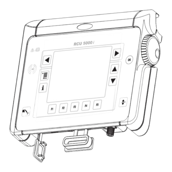
(10) (11) (12) (13) (14) RCU 5000i control panel Action keys Menu key ... for calling up the main menu Info key ... for displaying context-specific information OK key ... for confirming menu dialogs, precautionary queries, etc. Feeder inching button ... for feeding the filler wire with no accompanying flow of gas or current Gas test button ... -
Page 19: Information On Ok Key
Miscellaneous (15) Display ... black/white LCD (16) Keycard reader ... for identifying different access rights granted by means of a key- card Information on The OK key (3) aids the user in selecting the various function key functions. OK key If there is a border around a function key function, this function can be selected by pressing OK (3). -
Page 20: Other Controls, Connections, Mechanical Components
Rubber cover ... for protecting the USB-PC connection point (22) Bracket ... 0-95° hinged holder and (23) stand (23) M5 threaded insert ... e.g. for fix- ing to the wall (23) (23) (22) (23) RCU 5000i rear view - controls, mechanical compo- nents... - Page 21 (24) Memory card slot (25) USB port... for connecting to a PC, e.g. for software updates (25) (24) RCU 5000i side view - connections...
-
Page 22: Operating Concept
Operating concept Activities - orien- Operation instructions for the RCU 5000i remote control unit are divided according to ac- tation tivities. A distinction is made between the following activities: Welding (MIG/MAG Synergic, MIG/MAG manual, MMA, TIG and Job) Creating jobs... -
Page 23: Saving Values
The RCU 5000i remote control uses the "clothesline" principle as follows: -All parameters, displays and functions required for a selected activity are sorted ac- cording to the order in the "clothesline". Every data record in a "clothesline" is displayed in its own screen. -
Page 24: Description Of The Displays
Description of the displays General The RCU 5000i remote control unit uses various displays while operating. These so-called screens are called up using the menu, and serve as dialog with the user. "Menu" screen The "Menu" screen shows the main menu. To call up the "Menu" screen, press the Menu key (1). -
Page 25: Wizard" Screen
(4) (5) (6)(7) (10) (11) (12) (13) (14) (15) Example: "Data" screen Screen identifying character Time Activity (10) Filler metal, wire diameter, shield- ing gas Welding current (11) Information line User (12) Clothesline with screens A-E Screen title (13) Display area Welding voltage (14) Parameter list... -
Page 26: Dialogue" Screen
"Dialogue" The "Dialogue" screen is used for showing subdialogues. screen The "Dialogue" screen may contain hierarchical structures, pick lists, etc. Dark border F1 "Accept" F5 "Cancel" Example: "Dialogue" screen with "Accept" and "Can- cel" "Message" The "Message" screen displays certain statuses. The message must be acknowledged, or screen a decision must be taken. - Page 27 Current screen, shown in grey Symbol Error code Error description Dark border F3 "OK" Example: "Error" screen Current screen, shown in grey Symbol Error description Dark border F2 "Reset" F3 "Ignore" Example: "Error" screen with function keys "Reset" and "Ignore"...
-
Page 28: Start-Up
The following firmware is required on the power source to be able to operate the RCU ments 5000i remote control unit: OFFICIAL UST V 3.20.1 Connecting RCU The RCU 5000i remote control unit can be connected to any LocalNet socket on the weld- 5000i ing machine, e.g.: VR 4000 VR 7000... -
Page 29: Starting Sequence - Language Setting
Starting se- The following appear on the display during the starting sequence: quence - lan- Fronius logo (centre) guage setting Software version (bottom left) www.fronius.com (bottom right) language (F3 key) The starting sequence lasts approx. 2 seconds. The language and units (metric or imperial) can be preset during this time. -
Page 30: Error "073 (No Host)" - No Connection To The Power Source
Main menu appears in the selected langua- Main menu in the selected language Error "073 (no The non-resettable error "073 (no Host)" Host)" - No con- appears if the remote control cannot nection to the connect to the power source during com- power source missioning. -
Page 31: Locking And Unlocking The Rcu 5000I With A Keycard
Locking and unlocking the RCU 5000i with a keycard Requirement NOTE! The key card can be used for locking and unlocking the remote control, as long as there are no profiles or keys apart from "Administrator" and "Locked" in the "Machine pre-sets" menu item. -
Page 32: Unlocking The Rcu 5000I
(18). "MIG/MAG synergic welding" menu item in locked re- mote control, "Working parameters" screen Unlocking the Hold the keycard up to the keycard RCU 5000i reader (16) (16) Holding the keycard up to the keycard reader... -
Page 33: Unlock Rcu 5000I Using Unlock Function
All menu items can now be acces- sed without restrictions. "Info Key - The remote control is now unlocked" screen Unlock RCU 5000i An Unlock function has been added to the RCU 5000i remote control unit from software using Unlock version OFFICIAL RCU V1.14.12. function This Unlock function changes the "Locked"... -
Page 34: Mig/Mag Synergic Welding
MIG/MAG synergic welding General MIG/MAG synergic welding relates to synergic mode on the power source. Once the wire- feed speed parameter is set, the welding current and sheet thickness parameters are ad- justed accordingly. The current welding amperage and sheet thickness values appear in the display area. Call up "MIG/MAG Press the "Menu"... -
Page 35: Retrieving A Welding Program
Retrieving a welding program Retrieving a weld- Call up "MIG/MAG synergic welding" ing program menu item Select "Welding program" screen by pressing the right arrow key (8) – "Welding program" screen appe- MIG/MAG synergic welding: "Welding program" screen The "Welding program" screen contains the following data: Filler metal Wire diameter Shielding gas... -
Page 36: Setting Working Parameters
Setting working parameters Setting working Call up "MIG/MAG synergic welding" parameters menu item Select "Working parameters" screen by pressing the right arrow key (8): – "Working parameters" screen ap- pears. Select the corresponding working pa- rameters using down (6) or up (7) keys Use the adjusting dial (18) to alter the parameter value –... - Page 37 If the set welding program and the selected process do not correspond, or if there is no welding program for the selected process, "no program" appears in the display area. The "Wirefeed speed" parameter cannot be altered. MIG/MAG synergic welding: "Working parameters" screen, "no program"...
- Page 38 "Hotstart time" parameter for the CMT process "Pulse correction" parameter for the CMT process "Hotstart pulse cycles" parameter for the CMT process "Boost correction" parameter for the CMT process "Dynamic correction" parameter for the CMT process...
-
Page 39: Cmt" Process
"CMT" process The "CMT" process is only possible when combined with the following components: CMT power source (e.g. TPS 4000 CMT) CMT wirefeeder (e.g. VR 7000 CMT) CMT drive unit with wire buffer (e.g. Robacta Drive CMT) CMT interconnecting hosepack The M0842 welding database is required for the CMT Advanced process. -
Page 40: Switching To Extra-Large Display
Switching to extra-large display General The wirefeed speed, welding current and welding voltage parameters can be displayed in extra-large format. The wire feed unit and push-pull unit motor current is also shown in the "Extra-large display" screen as an actual value. Switching to ex- Call up "MIG/MAG synergic welding"... -
Page 41: Setting Process Settings Parameters
Setting process settings parameters Setting process Call up "MIG/MAG synergic welding" settings parame- menu item ters Select "Process settings" screen by pressing the right arrow key (8). – "Process settings" screen appears Select the process settings parameters using the down (6) or up (7) keys Change the value of the process set- tings parameters using the adjusting dial (18) -
Page 42: Setting Additional Parameters: Special 2-Step, Special 4-Step, Spot Welding
Setting additional parameters: special 2-step, spe- cial 4-step, spot welding Setting addition- If trigger mode S2-step is selected in the "Working parameters" screen, the corresponding al special 2-step screen is hung on the clothesline. parameters The following additional parameters can be set: Starting current Is Starting-current dur. -
Page 43: Setting Additional Special 4-Step Parameters
Setting addition- If S4-step trigger mode is selected in the "Working parameters" screen, the corresponding al special 4-step screen is hung on the clothesline. parameters The following additional parameters can be set: Starting current Is Slope 1 Sl1 Final current Slope 2 Sl2 Call up "MIG/MAG synergic welding"... -
Page 44: Setting Additional Spot Welding Parameters
Setting addition- If spot welding is selected as the trigger mode in the "Working parameters" screen, the cor- al spot welding responding screen is hung on the clothesline. parameters The following parameters can be set: Wire feed speed Arc length correction Spot welding time Call up "MIG/MAG synergic welding"... -
Page 45: Setting Synchropuls Parameters
Setting SynchroPuls parameters General If the SynchroPuls software option is installed on the power source, the screen for the Syn- chroPuls parameters is also available. The screen is added to the clothesline. Setting Synchro- Call up "MIG/MAG synergic welding" Puls parameters menu item (software option) Select "SynchroPuls"... -
Page 46: Mig/Mag Standard Manual Welding
MIG/MAG standard manual welding General Unlike MIG/MAG synergic welding, in MIG/MAG manual welding the welding parameters are set individually. Call up "MIG/MAG Press the "Menu" button (1): standard manual – Main menu appears welding" menu Select "MIG/MAG standard manual item welding"... -
Page 47: Retrieving A Welding Program
Retrieving a welding program Select welding Call up "MIG/MAG standard manual program welding" menu item Select "Welding program" screen by pressing the right arrow key (8) – "Welding program" screen appe- MIG/MAG standard manual welding: "Welding pro- gram" screen The "Welding program" screen contains the following data: Filler metal Wire diameter Shielding gas... -
Page 48: Setting Working Parameters
Setting working parameters Setting working Call up "MIG/MAG standard manual parameters welding" menu item Select "Working parameters" screen by pressing the right arrow key (8) – "Working parameters" screen ap- pears Select the corresponding working pa- rameters using down (6) or up (7) keys Use the adjusting dial (18) to alter the parameter value –... -
Page 49: Switching To Extra-Large Display
Switching to extra-large display General The wirefeed speed, welding current and welding voltage parameters can be displayed in extra-large format. The wire feed unit and push-pull unit motor current is also shown in the "Extra-large display" screen as an actual value. Switching to ex- Call up "MIG/MAG standard manual tra-large display... -
Page 50: Setting Process Settings Parameters
Setting process settings parameters Setting process Call up "MIG/MAG standard manual settings parame- welding" menu item ters Select "Process settings" screen by pressing the right arrow key (8) – "Process settings" screen appears Select the process settings parameters using the down (6) or up (7) keys Change the value of the process set- tings parameters using the adjusting dial (18). -
Page 51: Setting Additional Spot Welding Parameters
Setting additional spot welding parameters Setting addition- If spot welding is selected as the trigger mode in the "Working parameters" screen, the cor- al spot welding responding screen is hung on the clothesline. parameters The following parameters can be set: Wire feed speed Arc length correction Spot welding time... -
Page 52: Setting Welding Program And Filler Metal
Setting welding program and filler metal General The welding program and filler metal can be set in the following menu items: MIG/MAG synergic welding MIG/MAG standard manual welding Optimising & managing jobs (only for saved MIG/MAG jobs) Setting welding In the relevant "Data" screen, press F4 program and filler "Filler metal"... - Page 53 Select corresponding gas using the ad- justing dial (18) Press F2 "Forward": – The "Select a reference" screen only appears if there are several characteristics for the selected fil- ler metal, wire diameter and shiel- ding gas. – The value given in brackets after the process indicates how many characteristics there are for this process.
-
Page 54: Plotting User Characteristics - Optimising A Characteristic
Plotting user characteristics - optimising a charac- teristic General "Creating new user characteristics - Optimize characteristics" can only be carried out in the MIG/MAG synergic welding menu item. The basics of Every welding program is based on a welding characteristic. The characteristics of select- plotting user ed welding programs can be altered to suit a specific user. - Page 55 Select the lower and upper power li- mits using down (6) or up (7) keys Set lower and upper power limit using the adjusting dial (18) – The parameter value can only be altered within the defined setting range. The setting range is high- lighted.
- Page 56 Select corresponding characters using the adjusting dial (18) Press F4 ">" to enter the next charac- – Corrections can be carried out using F3 "<" or F2 "< Delete" Press F1 "Accept" when finished: – The new name is accepted, "Opti- mize characteristics"...
-
Page 57: Creating New Characteristic Points For User Characteristics
Creating new characteristic points for user charac- teristics General The "Create new characteristic point" function can be performed in the following menu items: MIG/MAG synergic welding MIG/MAG standard manual welding The basics of Various parameter settings can be saved in the user characteristics as characteristic plotting new char- points. - Page 58 Press F2 "Yes" or F3 "No" or F4 "Can- cel" – If a standard characteristic point is to be added to a pulse characteri- stic or vice versa, an error messa- ge appears. Precautionary query: characteristic point does not match Press F3 "OK"...
- Page 59 Select corresponding characters using the adjusting dial (18) Press F4 ">" to enter the next charac- – Corrections can be carried out using F3 "<" or F2 "< Delete". Press F1 "Accept" when finished: – The new name is accepted, "Cre- ate new characteristic point"...
-
Page 60: Selecting User Characteristics
Selecting user characteristics Selecting user In the corresponding "Data" screen, characteristics press F4 "Filler metal": – The 1st screen in the wizard appe- ars ("Select a filler metal") Select "User characteristic" using the adjusting dial (18) Press F2 "Forward": – The 2nd screen in the wizard ap- pears ("Select a user characteri- stic") -
Page 61: Mma Welding
MMA welding Call up "Rod elec- Press the "Menu" button (1) trode (MMA) – Main menu appears welding" menu Select "Rod electrode (MMA) welding" item menu item using the adjusting dial (18) Press OK (3) – The last "Data" screen called up appears Main menu: "Rod electrode (MMA) welding"... -
Page 62: Switching To Extra-Large Display
Switching to ex- The welding current and welding voltage parameters can be displayed in extra-large for- tra-large display mat: Call up "Rod electrode (MMA) welding" menu item Select "Extra-large display" screen by pressing the right arrow key (8) – "Extra-large display" screen appe- –... -
Page 63: Tig Welding
TIG welding Call up "TIG weld- Press the "Menu" button (1) ing" menu item – Main menu appears Select "TIG welding" menu item using the adjusting dial (18) Press OK (3) – The last "Data" screen called up appears Main menu: "TIG welding" menu item selected Setting working Call up "TIG welding"... -
Page 64: Switching To Extra-Large Display
Switching to ex- The welding current and welding voltage parameters can be displayed in extra-large for- tra-large display mat: Call up "TIG welding" menu item Select "Extra-large display" screen by pressing the right arrow key (8) – "Extra-large display" screen appe- –... -
Page 65: Cc/Cv Mode
Parameter changes in the "CC/CV mode" menu item can be made via a robot control or the RCU 5000i remote control. "CC/CV mode" is used in hot wire applications, for example. Call up "CC/CV Press the "Menu"... -
Page 66: Switching To Extra-Large Display
Switching to ex- The wirefeed speed, voltage command value and current command value parameters can tra-large display be displayed in extra-large format: Call up "CC/CV mode" Select "Extra-large display" screen by pressing the right arrow key (8) – "Extra-large display" screen appe- –... -
Page 67: Job Welding
Job welding Call up the "Job Press the "Menu" button (1) welding" menu – Main menu appears item Select "Job welding" menu item using the adjusting dial (18) Press OK (3) – The last "Data" screen called up appears Main menu: "Job welding" menu item selected Setting working If correction boundaries for a selected job are defined in the "Optimizing &... -
Page 68: Switching To Extra-Large Display
Switching to ex- For a selected job, the wirefeed speed, welding current and welding voltage parameters tra-large display can be displayed in extra-large format. Call up the "Job welding" menu item Select "Extra-large display" screen by pressing the right arrow key (8) –... -
Page 69: Saving Settings As A Job
Saving settings as a job General The "Store as job" function can be performed in the following menu items: MIG/MAG synergic welding CC/CV mode Job welding Optimizing & managing jobs Instructions on Set all parameters in all screens displayed storing jobs –... - Page 70 Press F2 "Forward": – The 2nd screen in the wizard ap- pears ("Store as job - Memory location") "Store as job - Group" screen: no. 6 SR 71 selected Select corresponding job using the ad- justing dial (18) Press F3 "Name job" to name the job: –...
- Page 71 Press F2 "Forward": – The 3rd screen in the wizard ap- pears as confirmation ("Store as job"). – By pressing F1 "Back", the screens of the steps already per- formed can be displayed again. Changes can be made. "Store as job - Memory location" screen: Job 61 Test selected Press F2 "Done": –...
-
Page 72: Internal/External Adjustment Of Selected Parameters
"Wirefeed speed" parameter must be set on the wire-feed unit. If the parameter value is to be set on the RCU 5000i re- mote control unit, the "wirefeed speed" parameter must be converted to internal parameter entry. - Page 73 IMPORTANT! The F5 "Int/Ext" function key is only active when a remote control is con- nected. If the remote control is not connected, the F5 "Int/Ext" function key is greyed out: Example of an unconnected remote control unit: F5 "Int/Ext" greyed out...
-
Page 74: Optimizing And Managing Jobs
Optimizing and managing jobs General For selected jobs, the following functions can be performed in the "Optimizing & managing jobs" menu item: Retrieving administration data Setting working parameters Setting job-specific parameters Depending on the type of the selected job, many different screens are displayed on the "clothesline". -
Page 75: Overview
Press F2 "Yes" or F3 "No" – Online editing - F2 "Yes" The power source changes to the job correction menu, independent of the current power source set- tings. Data changed on the remote control unit also appear on the po- wer source. -
Page 76: Manage Jobs
Manage jobs Managing jobs Call up the "Optimizing & managing jobs" menu item Whatever screen is showing, press F1 "Manage jobs": – The 1st screen in the wizard appe- ars ("Manage jobs - Group") Select desired group (0 - 99) using the adjusting dial (18) Press F3 "Name group"... - Page 77 Select desired memory location using the adjusting dial (18) Press F3 "Name job" to name the job: – "Name job" screen appears "Manage jobs - Memory location" screen Select corresponding characters using the adjusting dial (18) Press F4 ">" to enter the next charac- –...
-
Page 78: Deleting Groups And Jobs
Deleting groups Call up the "Optimizing & managing and jobs jobs" menu item Whatever screen is showing, press F1 "Manage jobs": – The 1st screen in the wizard appe- ars ("Manage jobs - Group") When deleting groups, select groups to be deleted (0 - 99) using the adjusting dial (18) Press F4 "Delete group"... - Page 79 When deleting jobs, select relevant memory location using adjusting dial (18) Press F4 "Delete job": – Precautionary query "Do you real- ly want to delete job 3?" appears "Manage jobs - Memory location" screen Press F2 "Yes" – The selected job is deleted, the 2nd screen in the wizard appears ("Manage jobs - Memory locati- on")
-
Page 80: Retrieving Administration Data For A Selected Job
Retrieving administration data for a selected job Retrieving admin- Call up the "Optimizing & managing istration data for jobs" menu item a job Select "Administration data" screen by pressing the right arrow key (8) – "Administration data" screen ap- pears Select "group no."... -
Page 81: Retrieving And Changing A Welding Program For A Selected Job
Retrieving and changing a welding program for a se- lected job General The sequence of screens shown on the "clothesline" depends on the type of job selected. The "Welding program" screen only appears with MIG/MAG synergic jobs. Retrieving a job Call up the "Optimizing &... - Page 82 Select required filler metal using the adjusting dial (18) Press F2 "Forward": – The 2nd screen in the wizard ap- pears ("Select a wire diameter") – Only the wire diameters available for the filler metal selected in the 1st screen are shown. "Select a filler metal"...
- Page 83 Select the corresponding process using the down (6) or up (7) keys Select the corresponding characteri- stic reference number using the adjus- ting dial (18) – E.g.: Characteristic C0876 is only suita- ble for CMT. Press F2 "Forward" – The 4th screen in the wizard ("Welding program") is shown as a confirmation –...
-
Page 84: Retrieving And Changing Working Parameters For A Selected Job
Retrieving and changing working parameters for a selected job General The sequence of screens shown on the "clothesline" depends on the type of job selected. Retrieving and Call up the "Optimizing & managing jobs" menu item changing job Whatever screen is showing, select "Group n°" parameter using the down (6) or up (7) working parame- keys ters... -
Page 85: Retrieving And Changing Process Settings For A Selected Job
Retrieving and changing process settings for a se- lected job General The sequence of screens shown on the "clothesline" depends on the type of job selected. Retrieving and Call up the "Optimizing & managing jobs" menu item changing job pro- Whatever screen is showing, select "Group n°"... -
Page 86: Retrieving And Changing Special 2-Step Parameters For A Selected Job
Retrieving and changing special 2-step parameters for a selected job General The sequence of screens shown on the "clothesline" depends on the type of job selected. "Special 2-step" screen only appears: if the trigger mode is set to S2-step for the job selected for MIG/MAG synergic jobs Retrieving and Call up the "Optimizing &... -
Page 87: Retrieving And Changing Special 4-Step Parameters For A Selected Job
Retrieving and changing special 4-step parameters for a selected job General The sequence of screens shown on the "clothesline" depends on the type of job selected. The "Special 4-step" screen only appears: if the trigger mode is set to S4-step for the job selected for MIG/MAG synergic jobs Retrieving and Call up the "Optimizing &... -
Page 88: Retrieving And Changing Spot Welding Parameters For A Selected Job
Retrieving and changing spot welding parameters for a selected job General The sequence of screens shown on the "clothesline" depends on the type of job selected. The "Spot welding" screen only appears: if the trigger mode is set to S4-step for the job selected for MIG/MAG synergic jobs Retrieving and Call up the "Optimizing &... -
Page 89: Establishing Correction Boundaries For A Selected Job
Establishing correction boundaries for a selected General The sequence of screens shown on the "clothesline" depends on the type of job selected. The "Correction boundaries" screen only appears with MIG/MAG synergic jobs. Purpose of cor- Correction boundaries can be entered individually for each job. rection bounda- If correction boundaries are set for a job, welding power and arc length of the job con- ries... -
Page 90: Explanation Of Correction Boundaries
Explanation of The correction range for welding power is made up as follows: correction bound- set wirefeed speed E.g.: 15.0 m/min aries value as % for upper power correction limit upper limit for welding power 15.8 m/min set wirefeed speed E.g.: 15.0 m/min... -
Page 91: Job-Specific Documentation
Job-specific documentation General The sequence of screens shown on the "clothesline" depends on the type of job selected. Purpose of the "Job-specific doc." is for documenting the current welding values of a selected job. "Job-specific "Job-specific doc." can be set individually for each job. doc."... -
Page 92: Explanation Of Job-Specific Documentation
Explanation of Parameter Setting Result job-specific docu- Documentation In job welding, the present welding values in the mentation selected job are documented according to the "Every n-th seam" and "Every n seconds" param- eters The present welding values in the selected job are not documented in job welding Every n-th seam In job welding, the present welding values in the... -
Page 93: Retrieving And Changing Synchropuls Parameters For A Selected Job
Retrieving and changing SynchroPuls parameters for a selected job General The sequence of screens shown on the "clothesline" depends on the type of job selected. The "SynchroPuls" screen only appears: if the SynchroPulse option is installed on the power source for MIG/MAG synergic jobs Retrieving and Call up the "Optimizing &... -
Page 94: Establishing Qmaster Values For A Selected Job
Establishing QMaster values for a selected job General The sequence of screens shown on the "clothesline" depends on the type of job selected. Purpose of QMas- QMaster values can be entered individually for each job. If set QMaster values are exceed- ter values ed or not reached over a specific period, one of the following reactions takes place: Power source switches off immediately... -
Page 95: Explanation Of Qmaster Values
Explanation of Current set value E.g.: 338.0 QMaster values value in A for upper current limit upper welding current limit value 344.0 Current set value E.g.: 338.0 value in A for lower current limit lower welding current limit value 332.0 Maximum duration of current deviation E.g.: Reaction... -
Page 96: Determining Qmaster Wirefeed Speed Values For A Selected Job
Determining QMaster wirefeed speed values for a selected job General The sequence of screens shown on the "clothesline" depends on the type of job selected. Purpose of QMas- QMaster values can be entered individually for each job. If set QMaster values are exceed- ter values ed or not reached over a specific period, one of the following reactions takes place: Power source switches off immediately... -
Page 97: Explanation Of Q-Master Wire Feed Speed Values
Explanation of Q- Wire feed speed command value E.g.: 15.0 m/min Master wire feed Value for the lower wirefeed speed limit m/min speed values upper welding current limit value 14.5 m/min Wire feed speed command value E.g.: 15.0 m/min Value for the upper wirefeed speed limit m/min upper wirefeed speed limit value 15.5... -
Page 98: Optimizing And Managing Characteristics
Optimizing and managing characteristics General In the "Optimizing & managing characteristics" menu item, user characteristics can be managed, renamed or optimized. NOTE! Optimizing user characteristics requires knowledge of arc and welding technology. IMPORTANT! At least two characteristic points are needed to create a user characteristic. To optimise all power ranges, however, 6-10 characteristic points should be programmed (one point per material strength). -
Page 99: Overview
Overview "Optimizing & managing characteristics" is composed of the following sections: Managing characteristics Managing characteristic points Parameters of standard characteristics Parameters of pulse characteristics Parameters of CMT characteristics Parameters of CMT / pulse characteristics Parameters of CMT Advanced characteristics Parameters of CMT/Pulsed Advanced characteristics Changing characteristic parameters... -
Page 100: Manage Characteristics
Manage characteristics Select character- Call up "Optimizing & managing cha- istics racteristics" menu item – The last "Data" screen called up appears. Whatever screen is showing, press F1 "Managing characteristics": – The 1st screen in the wizard appe- ars ("Managing characteristics") Example of a "Data"... -
Page 101: Naming And Renaming Characteristics
Naming and re- Call up "Optimizing & managing cha- naming charac- racteristics" menu item teristics – The last "Data" screen called up appears. Whatever screen is showing, press F1 "Managing characteristics": – The 1st screen in the wizard appe- ars ("Managing characteristics") Example of a "Data"... -
Page 102: Deleting Characteristic
Press F5 "Cancel" "Managing characteristics" screen The last "Data" screen called up appears. Example of a "Data" screen for characteristic XYZ Deleting charac- Call up "Optimizing & managing cha- teristic racteristics" menu item – The last "Data" screen called up appears. - Page 103 Select the desired characteristic using the adjusting dial (18) Press F2 "Delete characteristic" – Precautionary query "Do you real- ly want to delete Synergic ...?" ap- pears "Managing characteristics" screen Press F2 "Yes" – The characteristic is deleted, "Ma- naging characteristics" screen ap- pears Precautionary query "Do you really want to delete Sy- nergic ...?"...
-
Page 104: Managing Characteristic Points
Managing characteristic points Select character- Call up "Optimizing & managing cha- istic points racteristics" menu item – The last "Data" screen called up appears. Press F1 "Managing characteristics" and select the corresponding characte- ristic Whatever screen is showing, select the characteristic point to be altered by pressing F2 or F5: –... - Page 105 Using the adjusting dial (18), choose whether to calculate or to copy the cha- racteristic point Calculating a characteristic point: Press F2 "Forward": – The 2nd screen in the wizard ap- pears ("Calculate characteristic point") "Insert characteristic point" screen - "Calculate" selec- using the adjusting dial (18), enter wi- refeed speed for which the new cha- racteristic point is to be calculated...
- Page 106 The new characteristic point is inserted into the characteristic, according to its wirefeed speed. The corresponding "Data" screen appears Example of a "Data" screen with new characteristic point (Point 1) Copying a characteristic point: Press F2 "Forward": – The 2nd screen in the wizard ap- pears as confirmation ("Characte- ristic point now copied") –...
-
Page 107: Deleting Characteristic Points
The currently selected characteristic point is copied into the characteristic, the corres- ponding "Data" screen appears. Example of a "Data" screen with copied characteristic point (Point 3) Deleting charac- Call up "Optimizing & managing cha- teristic points racteristics" menu item –... - Page 108 The selected characteristic point is deleted, the corresponding "Data" screen appears. Example of a "Data" screen for characteristic XYZ...
-
Page 109: Parameters Of Standard Characteristics
Parameters of standard characteristics Ignition Feeder creep speed Wire feed speed [m/min] before welding begins (0 - currently set wire feed speed) Ignition current time The length of time [ms] that the set ignition current is active when welding begins no ignition current max. -
Page 110: Arc (Dynamic)
Effects of excessively low voltage: arc too short - unstable arc The wire electrode is not sufficiently melted - heavy spatter due to wire electrode pen- etrating the welding material Characteristic slope Resistance value [μOhm] with which a drooping or neutral characteristic can be set. 32767 drooping characteristic neutral characteristic... -
Page 111: End Of Welding
Current drop The current drop parameter determines the speed at which the short circuit current con- trol changes to voltage control. flat drop (soft arc, tending towards instability) 65535 steep drop (hard, stable arc) Current rise The current rise parameter determines the speed at which the welding current increases for the duration of the short circuit. -
Page 112: Accepting Voltage And Current Guideline Values
Accepting volt- Voltage and current guideline values are accepted by the remote control unit directly from age and current the test weld: guideline values Set welding voltage and welding cur- rent at the power source Perform test weld – During the welding process, the present values for welding voltage and welding current appear as ac- tual values on the remote control... -
Page 113: Parameters Of Pulse Characteristics
Parameters of pulse characteristics Ignition Feeder creep speed Wire feed speed [m/min] before welding begins (0 - currently set wire feed speed) Ignition current time The length of time [ms] the ignition current set when welding begins is active. no ignition current max. - Page 114 Ground current The function of the base current [A] is to maintain the arc during the pause between the pulses (= base current phase). Effects of an excessively high base current: wire electrode welded on too hard large drops form Effects of an excessively low base current: ionisation of the arc section too low Arc breaks in the base current phase...
-
Page 115: Arc (Static)
Tau current drop Time of transition [ms] from a linear slope to the droplet detachment current (0 - 5) hard transition, loud arc noise soft transition, softer arc noise Droplet detachment current The droplet detachment current [A] is effective in the decreasing steep edge of a pulse, and serves to produce the best droplet detachment. - Page 116 Fact-f-control (p) Effect of deviations [%] on the frequency (0 - 50) Fact-I_b-correction Effect of arc length correction [%] on the base current (0 - 50) Fact-I_p1-correction Effect of arc length correction [%] on the pulsing current (0 - 50) Fact-f-correction Effect of arc length correction [%] on the frequency (0 - 50) The factors Fact-I_b correction, Fact-I_p1 correction and Fact-f correction enable arc...
-
Page 117: Short Circuit
Short circuit Current-rise (short circuit) The parameter [A/ms] describes how the current is ramped up in the event of a short circuit. End of welding Burn-back time The burn-back time [s] can be saved for each characteristic point. 0.00 minimum burn back time (risk of wire sticking to weld pool) 0.40 maximum burn back time (risk of wire sticking to contact tube) Guideline values... -
Page 118: Parameters Of Cmt Characteristics
Parameters of CMT characteristics General NOTE! The creation and editing of CMT characteristics is a complex task and therefore a core skill of Research & Development. Special measurement technol- ogy (e.g. a high-speed camera, oscilloscope) as well as extensive background knowledge is required for the creation and editing of CMT characteristics. -
Page 119: Cmt Parameters
slaghammer On_1/Off_0 Function for removing slag at the end of the wire electrode. The wire electrode carries out a quick forward and reverse movement and touches the surface of the workpiece until any slag drops off the wire electrode and ignition occurs. The ignition parameter for aluminium is slaghammer = 0. -
Page 120: End Of Welding
d_boostup Linear current rise rate [A/ms] at the start of the boost phase no current rise 1000 maximum rise in current (10) tau_boostup Non-linear current rise rate [ms] at the start of the boost phase (0.08 - 5.00) (11) I_boost Non-linear current rise rate [ms] at the start of the boost phase (0.08 - 5.00) (12) t_I_boost... -
Page 121: Accepting Voltage And Current Guideline Values
Wirefeed speed The guideline value for the wire feed speed [m/min] is normally determined by trial and er- ror or by performing a test weld. Accepting volt- Voltage and current guideline values are accepted by the remote control unit directly from age and current the test weld: guideline values... -
Page 122: Parameters Of Cmt / Pulse Characteristics
Parameters of CMT / pulse characteristics General NOTE! The creation and editing of CMT/pulse characteristics (CMT+P) is a com- plex task and therefore a core skill of Research & Development. Special meas- urement technology (e.g. a high-speed camera, oscilloscope, etc.) as well as extensive background knowledge is required for the creation and editing of CMT+P characteristics. -
Page 123: Overview: Cmt Parameters, Pulse Parameters
Overview: CMT parameters, pulse parameters (m/s) (12) t (s) (11) (10) I (A) (13) (14) (15) t (s) U (V) (16) (17) t (s) Overview of the CMT+P characteristic parameters Short-circuit phase CMT cycle Boost phase Pulse cycles Burn phase Plasma phase CMT parameters I_sc_wait... -
Page 124: Pulsing Parameters
Pulsing parame- d_pulsup ters Linear rate of rise in the pulsing current [A/ms] no pulsing current rise 1000 maximum pulsing current rise (10) tau_pulsup Non-linear rate of rise in the pulsing current [ms] (0.08 - 5) (11) I_p1 Current command value [A] during the pulse phase (12) vd_pulscycle Wire feed speed [m/min] during the pulse cycle (0 - 45) -
Page 125: End Of Welding
End of welding t_burnback Duration of the currentless wire withdraw [ms] after the welding current has been switched off (v = -6 m/min) Guideline values Current guideline value The current guideline value [A] is normally determined by trial and error or by performing a test weld. -
Page 126: Parameters Of Cmt Advanced Characteristics
Parameters of CMT Advanced characteristics General NOTE! The creation and editing of CMT/pulse characteristics (CMT+P) is a com- plex task and therefore a core skill of Research & Development. Special meas- urement technology (e.g. a high-speed camera, oscilloscope, etc.) as well as extensive background knowledge is required for the creation and editing of CMT+P characteristics. -
Page 127: Weld Start
Weld start Positive_weldstart_cycles Number of positive weld start cycles Negative_weldstart_cycles Number of negative weld start cycles Summary_weldstart_cycles Total number of weld start cycles "Weld start" screen for CMT Advanced characteristics CMT parameters The CMT parameters are displayed in the screens "CMT - Param1" and "CMT - Param2". and EN-CMT pa- The EN-CMT parameters in the negative cycle are displayed on the "CMT - Param1"... - Page 128 vd_sc_wait (-6) EN_vd_sc_wait Wirefeed speed [m/min] following the boost phase until the dipping of the wire elec- trode into the weld pool I_sc2 (-7) EN_I_sc2 Current command value with short circuit [A] d_boostup (-8) EN_d_boostup Linear current rise rate [A/ms] at the start of the boost phase no current rise 1000 maximum rise in current...
-
Page 129: En/Ep Cmt
EN/EP CMT Positive_cycles Positive CMT cycles Negative_cycles Negative CMT cycles End of welding I_drop_melt EN_I_drop_melt Current command value [A] for globule formation at the end of welding (t=10 ms) no globule formation maximum globule formation t_burnback Duration of the currentless wire withdraw [ms] after the welding current has been switched off (v = -6 m/min) Guideline values... -
Page 130: Accepting Voltage And Current Guideline Values
Accepting volt- Voltage and current guideline values are accepted by the remote control unit directly from age and current the test weld: guideline values Set welding voltage and welding cur- rent at the power source Perform test weld – During the welding process, the present values for welding voltage and welding current appear as ac- tual values on the remote control... -
Page 131: Parameters Of Cmt/Pulsed Advanced Characteristics
Parameters of CMT/Pulsed Advanced characteris- tics General NOTE! The creation and editing of CMT/pulse characteristics (CMT+P) is a com- plex task and therefore a core skill of Research & Development. Special meas- urement technology (e.g. a high-speed camera, oscilloscope, etc.) as well as extensive background knowledge is required for the creation and editing of CMT+P characteristics. -
Page 132: Overview: Cmt Parameters, Pulse Parameters
Overview: CMT The CMT parameters are displayed in the screens "CMT - Param1" and "CMT - Param2". parameters, pulse The pulsing parameters are displayed on the "Pulsing parameter 1" and "Pulsing parame- parameters ter 2" screens. (m/s) (19) t (s) (14) (13) I (A) -
Page 133: Pulsing Parameters
tau_boostup Non-linear current rise rate [ms] at the start of the boost phase (0.08 - 5.00) I_boost Current command value [A] during the boost phase t_I_boost Duration [ms] of the boost phase from the start of the boost current rise until the start of the boost current decrease no boost phase 99.98... - Page 134 (16) d_Ip2 Linear pulsing current decrease rate t_p2 [A/ms] (14) I_p1 no decrease in puls- ing current 2200 maximum pulsing (16) d_Ip2 current drop (17) tau_Ip2 Non-linear pulsing current decrease I_p2 rate [ms] (17) tau_Ip2 I (A) d_I_Base I_p2 (18) I_base tau_I_base Droplet-detachment current [A] t (s)
-
Page 135: Pulsed/Cmt Cycles
k_I_p1_reg_gain Effect of deviations [%] on the pulsing current k_Vd_reg_gain Effect of deviations [%] on the wirefeed speed k_I_b_reg_gain Effect of arc length correction [%] on the base current I_p1_reg_delta_min Lower control limit for the pulsing current Ip1 [A] I_p1_reg_delta_max Upper control limit for the pulsing current Ip1 [A] Pulsed/CMT cy- N_CMT_Cycles... - Page 136 Wirefeed speed The guideline value for the wire feed speed [m/min] is normally determined by trial and er- ror or by performing a test weld.
-
Page 137: Changing Characteristic Parameters
Changing characteristic parameters The process con- The process controller appears in each screen of the "Optimizing & managing character- troller istics" menu item. This process controller supports optimization of pulse characteristics by means of the control parameters Fact-I_b control (pi), Fact-I_p1 control (pi) and Fact-f con- trol (p) Process controller with setting ranges (1) optimum range... -
Page 138: Changing Characteristic Parameters
Changing charac- Call up "Optimizing & managing characteristics" menu item teristic parame- – The last "Data" screen called up appears. ters Press F1 "Managing characteristics" and select the corresponding characteristic Whatever screen is showing, use the right arrow key (8) to select the "Data" screen in which the characteristic parameter to be changed is located Using F2 or F5, select the characteristic point whose characteristic parameter is to be changed:... -
Page 139: Documentation
"CC/CV mode" (if the "CC/CV mode" software option is installed on the power source) "Job welding" Evaluating weld- The documented welding data can be evaluated in two ways: ing data RCU 5000i RCU 5000i Direct evaluation of welding data Storing welding data on a memory card, subsequent evaluation... -
Page 140: Call Up The "Documentation" Menu Item
RCU 5000i remote control RCU 5000i remote control If there is no LocalNet connection If there is no LocalNet connection free on the power source: LocalNet free on the power source: LocalNet passive distributor passive distributor Welding data which is evaluated directly can also be stored on the memory card. -
Page 141: Establishing Basic Settings For The Documentation
Establishing basic settings for the documentation Establishing ba- Call up the "Documentation" menu sic settings for item the documenta- Select "Basic settings" screen by pres- tion sing the right arrow key (8) – "Basic settings" screen appears Select the corresponding parameter using the down (6) or up (7) keys Alter the parameter using the adjusting dial (18) -
Page 142: Documentation On Memory Card
The actual welding values are documented every 0.2 seconds The actual welding values are documented every 9.9 seconds (maxi- mum) e.g. in the case of long welds A common value for the "Every n seconds" parameter is 0.5 sec. Job documentation for activating/deactivating the documentation function for a selected job Range Off/on/per job... - Page 143 0.1, duty cycle 100%) change a full memory card within a maximum of 4 minutes, otherwise the data buffered on the RCU 5000i remote control unit will be lost. The RCU 5000i remote control unit supports 32MB - 1GB memory cards.
-
Page 144: Establishing Qmaster Values
Establishing QMaster values Purpose of QMas- Q-Master values can be established in the "Documentation" menu item. When storing jobs ter values these QMaster values are accepted as pre-sets. If during job welding set QMaster value limits are exceeded over a specific period, one of the following reactions results: Power source switches off immediately A warning signal is given No reaction... - Page 145 Welding voltage according to job E.g.: 35.0 value in V for upper voltage limit upper voltage limit 37.1 Welding voltage according to job E.g.: 35.0 value in V for lower voltage limit lower voltage limit 31.4 Maximum duration of current deviation E.g.: Reaction E.g.:...
-
Page 146: Setting Maximum Motor Current
Setting maximum motor current General In the "Documentation" menu item, the maximum motor current can be defined for the wire- feed motor and the motor of a push-pull unit. When storing jobs, these maximum motor cur- rent values are used as pre-sets. If the defined motor current values are exceeded for a certain period during welding, then one of the following will occur: Power source switches off immediately A warning signal is given... -
Page 147: Component Counter
Component counter General A component counter function is provided in the "Documentation" menu item. Using the part counter, consecutive numbers can be assigned to any desired parts or workpieces. Each part can be precisely identified through the assigned number, e.g. when an error oc- curs. - Page 148 Select corresponding characters using the adjusting dial (18) Press F4 ">" to enter the next charac- – Corrections can be carried out using F3 "<" or F2 "< Delete" Press F1 "Accept" when finished: "Enter component number" screen The new component number is accepted, the "Component counter"...
-
Page 149: Incrementing The Component Number
Incrementing the Incrementing the part number can be performed manually using F1 and F2 or by job. component num- Call up the "Documentation" menu item Select "Component counter" screen by pressing the right arrow key (8) – "Component counter" screen ap- pears Select the "Increment"... -
Page 150: Welding Log
Welding log General The welding data of all MIG/MAG welding operations (Synergic, manual, job) from welding start-up through the sections up to the end of welding are recorded in the welding log. Displaying weld- Call up the "Documentation" menu ing data from the item welding log Select "Welding log"... - Page 151 The welding data of the respective section is displayed. "Welding information" screen for seam 2, section 1...
-
Page 152: Event Log
General The following data are recorded in the event log: User logons/logoffs Changes to jobs Faults and their rectification Updates to RCU 5000i software The event log holds approx. 400 entries. Event log Call up the "Documentation" menu item Select "Event log" screen by pressing the right arrow key (8) –... -
Page 153: Removing A Memory Card
Removing a memory card General The memory card must be removed from the remote control unit (e.g. during weld-off times) in order to evaluate the data. The memory card can be removed at any time. Removing a mem- NOTE! When documenting to a memory card, always press F5 "Remove SD ory card card"... - Page 154 Removing a memory card Save complete. The memory card can now be removed. "Information - Save complete" screen...
-
Page 155: Machine Pre-Sets
Setting machine pre-sets for weld- RCU 5000i - Unlock function Setting the language and units of measurement Ethernet setting RCU 5000i - displaying version data Setting date and time Robot interface - robot welding Creating backup Profiles / Keys Restoring data... -
Page 156: Setting Machine Pre-Sets For Welding
Setting machine pre-sets for welding Setting machine Call up the "Machine pre-sets" menu pre-sets for "MIG/ item MAG" Select "MIG/MAG" screen by pressing the right arrow key (8) – "MIG/MAG" screen appears Select the corresponding pre-set using down (6) or up (7) keys Alter the value of the pre-sets using the adjusting dial (18) –... -
Page 157: Setting Machine Pre-Sets For "Rod Electrode (Mma) Welding
Setting machine Call up the "Machine pre-sets" menu pre-sets for "Rod item electrode (MMA) Select "Rod electrode (MMA) welding" welding" screen by pressing the right arrow key – The "Rod electrode (MMA) wel- ding" screen appears Select the corresponding pre-set using down (6) or up (7) keys Alter the value of the pre-sets using the adjusting dial (18) -
Page 158: Ethernet Setting
Ethernet is a way of including a power source in a local network. If the Ethernet option (UBST PCB with Ethernet connection) is installed on the power source, then the screen for setting the Ethernet parameters will be available on the RCU 5000i. The screen is added to the clothesline. -
Page 159: Ethernet Parameters
Ethernet parame- IP address ters Each power source in a local network is assigned its own IP address. The respective pow- er source can be identified and addressed via this IP address. Subnet mask Subnet mask is a network-specific parameter of the local network. Setting the "Subnet mask"... -
Page 160: Setting Date And Time
Setting date and time Setting date and Call up the "Machine pre-sets" menu time item Select "Time/date" screen by pressing the right arrow key (8) – "Time/date" screen appears Select the corresponding parameter using the down (6) or up (7) keys Alter the parameter using the adjusting dial (18) –... -
Page 161: Robot Interface - Robot Welding
Robot interface - robot welding General The RCU 5000i remote control unit automatically recognises when the welding machine is connected to a robot control via a robot interface (robot welding). In the "Robot interface" screen, the user can switch between internal and external param-... -
Page 162: External Parameter Control In Robot Welding
"Robot interface" screen appears Set "general parameter control" para- meter to "External" using the adjusting dial (18) – The RCU 5000i remote control unit changes to external parame- ter control. – The parameters to be set are en- tered and altered via the robot control. -
Page 163: Selective External/Internal Switching Of Selected Parameters With External Parameter Control
Selective exter- With external parameter control, the user can select and switch between external/internal nal/internal for selected parameters using F5 "Int/Ext". The external parameters can therefore be al- switching of se- tered and set internally on the remote control unit. lected parameters The function key F5 "Int/Ext"... -
Page 164: Other Functions In Robot Welding
MIG/MAG synergic welding: "Working parameters" screen, trigger mode selected - F5 "Int/Ext" disabled Other functions in Selecting menu items robot welding In robot welding, the following menu items can be selected: Welding process currently selected by the robot Optimizing & managing jobs Optimizing &... - Page 165 E.g.: Robot working in "MIG/MAG synergic welding" process "MIG/MAG synergic welding" menu item has been opened by the user, "Process set- tings" screen is selected Robot changes to "Job welding" The remote control display automatically changes to the last "Data" screen displayed in the "Job welding"...
-
Page 166: Profiles/Keys
Profiles/keys General Users can be managed in the "Profiles / Keys" screen. User management is advisable if several users work with the same remote control unit. User management operates on a profile principle, using a system of key cards (item number 43,0001,1168). Users are as- signed different profiles depending on their level of training or qualifications. -
Page 167: Explanation Of Terms Used
If no other keys or profiles apart from "Administrator" and "Locked" are defined, any key card can lock and unlock the remote control. When the remote control is locked, the "Locked" profile is activated (see also section "Locking and unlocking the RCU 5000i with a key card"). -
Page 168: Administrator" Profile
"Administrator" The "Administrator" profile cannot be deleted, renamed or edited. profile "Locked" profile The "Locked" profile cannot be deleted or renamed. The "Locked" profile can be edited, in order to enable various screens and functions as necessary. The "Locked" profile is activated if no other key is logged onto the remote control. No keys can be assigned to the "Locked"... -
Page 169: Recommendation For Creating Profiles And Keys
NOTE! Incorrectly created profiles and keys can have serious consequences. In- correctly created profiles and keys can lead to key cards not being recognised or granted access, in which case the RCU 5000i remote control unit locks. Please read the following points carefully and keep to this recommendation when creating profiles and keys. -
Page 170: Creating And Editing Profiles
Creating and editing profiles Requirement An administrator key must first be created before profiles can be created. Create adminis- Call up the "Machine pre-sets" menu trator key item Call up "Profiles / Keys" screen by pressing the right arrow key (8) –... - Page 171 Select corresponding characters using the adjusting dial (18) Press F4 ">" to enter the next charac- – Corrections can be carried out using F3 "<" or F2 "< Delete" Press F1 "Accept" when finished: – When creating the 1st key, the 2nd screen in the wizard ("Regis- ter transponder") appears immedi- ately.
-
Page 172: Creating Profiles
Press F2 "Done" – "Profiles / Keys" screen appears "Confirmation" screen Creating profiles Call up the "Machine pre-sets" menu item Call up "Profiles / Keys" screen by pressing the right arrow key (8) – "Profiles / Keys" screen appears Press F3 "New profile" –... - Page 173 Press F3 "Name profile" – "Name profile" screen appears "Enter the profile name" screen Select corresponding characters using the adjusting dial (18) Press F4 ">" to enter the next charac- – Corrections can be carried out using F3 "<" or F2 "< Delete" Press F1 "Accept"...
- Page 174 Select function keys to be activated for the profile in question using the adjus- ting dial (18) To activate the functions, press F4 "Select" – An activated function key function is denoted by an X in the check box. "More settings" screen: "Create jobs"...
-
Page 175: Opening/Closing Profiles
Press F2 "Forward" – The last screen in the wizard ap- pears ("Confirmation"). Press F2 "Done" "Confirmation" screen The "Profiles / Keys" screen appears with the new profile. Machine pre-sets - "Profiles / Keys" screen with new profile Opening/closing Select desired profile using the adjus- profiles ting dial (18) Press F2 "Open profile"... -
Page 176: Editing Profile
To close the profile, press F2 "Close profile" Machine pre-sets - "Profiles / Keys" screen - "Adminis- trator" profile opened The profile is closed. Machine pre-sets - "Profiles / Keys" screen - "Adminis- trator" profile selected Editing profile Select desired profile using the adjus- ting dial (18) Press F4 "Edit profile"... - Page 177 Press F3 "Change profile name" to ch- ange the profile name – "Name profile" screen appears. "Change profile name" screen Select corresponding characters using the adjusting dial (18) Press F4 ">" to enter the next charac- – Corrections can be carried out using F3 "<"...
- Page 178 Select menu items and screens that are to be changed using adjusting dial (18) IMPORTANT! The higher-level menu item must also be activated in order to activate screens. Press F4 "Select" to activate a menu item or screen – An activated menu item or screen is denoted by an X in the check box.
- Page 179 Function key function Higher-level menu items Factory Default machine settings Modify (UBST-IP) Default machine settings Managing jobs Optimizing & managing jobs Managing characteristics Optimizing & managing characteristics Manage keys/profiles Default machine settings If the "Parameter access" function is activated, the user can alter the values of the selected parameter using the adjusting dial (18).
-
Page 180: Deleting Profile
Deleting profile Select desired profile using the adjus- ting dial (18) Press F5 "Delete profile" – Precautionary query "Do you real- ly want to delete the profile ... in- cluding all associated keys?" appears. Machine pre-sets - "Profiles / Keys" screen - "TIG Wel- ders"... -
Page 181: Example Profiles
Example profiles General For ease of reference, the lists in the following example profiles have been shown in their entirety. The size of the display on the remote control unit determines the way the lists are dis- played. The individual list entries are selected using the adjusting dial (18). Locked Factory settings for "Locked"... -
Page 182: Mig/Mag Welding Specialist
MIG/MAG welding Tasks: specialist Determining parameters for weld seams Create jobs Optimizing and managing jobs "More settings" screen "Menus and screens" screen Main menu in "MIG/MAG welding specialist" profile... -
Page 183: Robot Programmer
Robot program- Tasks: Establishing communication between robot control and welding machine Control function "More settings" screen "Menus and screens" screen Main menu in the "Robot programmer" profile... -
Page 184: Welder/Worker
Welder/worker Tasks: Welding jobs Performing backups Simple maintenance, e.g. replacing welding torch wearing parts (gas nozzle, contact tube, etc.), replacing feed rollers, wirespool "More settings" screen "Menus and screens" screen Main menu in the "Welder/worker" profile... -
Page 185: Creating And Editing Keys
Creating and editing keys Assigning key Using the adjusting dial (18), select the cards to profiles profile to which a key card is to be as- (key setup) signed Press F1 "New key" – The 1st screen in the wizard appe- ars ("Enter name") Machine pre-sets - "Profiles / Keys"... - Page 186 Press F2 "Forward": – The 2nd screen in the wizard ap- pears ("Register transponder") IMPORTANT! Do not duplicate any keys. Assign one key card to each user. "Enter name" screen Hold the keycard to be registered up to the keycard reader (16) –...
-
Page 187: Editing Users/Keys
Press F2 "Done" – "Profiles / Keys" screen appears "Confirmation" screen Editing users/ Open profile to which the key to be al- keys tered is assigned Select corresponding key using the ad- justing dial (18) Press F2 "Edit key": – The 1st screen in the wizard appe- ars ("Change name") "Profiles / Keys"... - Page 188 Select corresponding characters using the adjusting dial (18) Press F4 ">" to enter the next charac- – Corrections can be carried out using F3 "<" or F2 "< Delete" Press F1 "Accept" when finished: – The new name is accepted, "Ch- ange name"...
-
Page 189: Deleting Users/Keys
Press F3 "OK" Register other key cards – Otherwise, the last screen in the wizard appears ("Confirmation") "Error - key already exists" screen Press F2 "Done" – "Profiles / Keys" screen appears "Confirmation" screen Deleting users/ Open profile to which the key to be al- keys tered is assigned Select corresponding key using the ad-... - Page 190 Press F2 "Yes" Precautionary query "Do you really want to delete key ... ?" The selected key is deleted, the "Profiles / Keys" screen appears. Machine pre-sets, "Profiles / Keys" screen...
-
Page 191: Logging Registered Users On And Off At The Remote Control Unit
Logging registered users on and off at the remote control unit General Using the key cards, users can log on and off at the RCU 5000i remote control unit. Requirements: The user's key card must be registered on the RCU 5000i remote control unit and assigned to a profile. -
Page 192: Displaying Logged On Users
"Info Key - user logged in" screen Displaying On the RCU 5000i remote control, logged-on users are shown in the information bar in the logged on users "Data" screens, e.g.: Machine pre-sets - "Profiles / Keys" screen - user "A2"... -
Page 193: Logging Out A User
The "Locked" profile is activated. "Info Key - user logged out" screen Displaying If the "Locked" profile is activated on the RCU 5000i remote control, this is shown in the "Locked" profile information bar in the "Data" screens, e.g.: MIG/MAG synergic welding, "Welding program"... -
Page 194: Rcu 5000I - Unlock Function
RCU 5000i - Unlock function General An Unlock function has been added to the RCU 5000i remote control unit from software version OFFICIAL RCU V1.14.12. This Unlock function changes the "Locked" profile and enables access to the "Profile / Keys" screen in the machine pre-sets in order, for example, to add an Administrator key or modify the "Locked"... - Page 195 "UACCESS.TXT". Disconnect the RCU 5000i from the welding system or switch off the wel- ding system Insert memory card in the RCU 5000i Your RCU 5000i has been Connect the RCU 5000i to the welding unlocked. system or switch on the welding sys-...
-
Page 196: Further Actions
If the "Locked" profile is selected, the chan- ges can be displayed by pressing the F4 key "Change profile" and then pressing F2 "Forward": "More settings" screen in the "Locked" profile after "Menus and screens" screen in the "Locked" profile af- being changed using the Unlock function ter being changed using the Unlock function Further actions... -
Page 197: Setting The Language And Units Of Measurement
Setting the language and units of measurement General In machine pre-sets, the following user languages are currently available for setting in the "Language and units" screen: German Dutch English Chinese French Japanese Italian Korean Spanish Slovenian Czech Polish Swedish Finnish Portuguese (Brazil) Russian In addition, the user can choose between metric (mm, kg, m/min, l, etc.) and imperial units... -
Page 198: Displaying Version Data
Displaying version data General As long as the RCU 5000i remote control is connected to a power source, the version data for power source (UST), digital signal processor (DSP) and wire-feed unit (SR 41) as well as for the remote control are shown in the "Version" screen. -
Page 199: Creating Backup
Creating backup General With the "Backup" function, all data for the remote control can be saved: Current parameter settings Jobs User characteristics Set welding programs Default machine settings Documentation settings Set welding data, etc. The backup is saved on the memory card. The file format used here "*.FBC" is not normally visible. - Page 200 All data from the remote control unit are sa- ved onto the memory card "Backup" screen...
-
Page 201: Restoring Data
Restoring data General With the "Restore" function, existing backups can be spooled back into the remote control: The backup is transferred from the memory card to the remote control. Restoring data Insert the memory card containing the backup that is to be restored into the memory card slot (24) Call up the "Machine pre-sets"... - Page 202 The last "Data" screen called up appears "Restore" screen...
-
Page 203: Aligning Wirefeeder Or Push-Pull Unit
Aligning wirefeeder or push-pull unit Aligning wire- Each time changes are made to the wirefeeder (e.g. replacing wire-guide liners), it must feeder (VR align- be aligned. ment) Call up the "Machine pre-sets" menu item Select "MIG/MAG" screen by pressing the right arrow key (8) –... -
Page 204: Aligning The Push-Pull Unit
Press F2 "Done": "Confirmation" screen "MIG/MAG" screen appears. Machine pre-sets: "MIG/MAG" screen Aligning the The push-pull unit must be aligned prior to each initial start-up and each time the wirefeed- push-pull unit er software is updated. If the push-pull unit is not aligned, the standard parameters will be used - which may result in the welding result not being satisfactory. - Page 205 Select corresponding push-pull motor using the adjusting dial (18) Press F2 "Forward": – The 2nd screen in the wizard ap- pears ("Disengage the wire") "Select the push-pull motor" screen Follow the instructions given in the "Di- sengage the wire" screen Press F2 "Forward": –...
- Page 206 Follow the instructions given in the "Engage the wire" screen CAUTION! Risk of injury from wire electrode emerging at speed. Hold the welding torch so that it points away from your face and body. Press F2 "Done": – VR alignment is restarted, the 5th screen in the wizard appears ("Alignment under load") "Engage the wire"...
- Page 207 "MIG/MAG" screen appears. Machine pre-sets: "MIG/MAG" screen...
-
Page 208: L/R Alignment - Aligning Welding Circuit Inductivity And Welding Circuit Resistance
L/R alignment - aligning welding circuit inductivity and welding circuit resistance General If the following components on the welding machine are altered, welding circuit inductivity (L) and resistance (R) must be aligned: Torch hosepacks Interconnecting hosepacks Grounding (earthing) cables, welding cables Wire-feed units Welding torches, electrode holders Push-pull units... - Page 209 IMPORTANT! Contact between the earth- ing clamp and workpiece must be estab- lished on a cleaned area of the workpiece. Follow the instructions given in the "Preparations" screen – If TIG welding, place the tungsten electrode instead of the contact tube firmly in place.
- Page 210 The last "Data" screen called up appears Machine pre-sets: e.g. "MIG/MAG" screen...
-
Page 211: Rcu 5000I - Resetting To Factory Settings
RCU 5000i - Resetting to factory settings General The machine pre-sets for the remote control unit can be reset to the factory settings at any time. This deletes all data. It is recommended to create a backup of this data before resetting the remote control unit. -
Page 212: Rcu 5000I - Updating Software
RCU 5000i - Updating software Requirements The following programs are required for updating the RCU 5000i software: LocalNetUSB driver (on the "Software Tools" CD-ROM) BASICLoad software V2.83.2 or higher (on the "Software Tools" CD-ROM) Current RCU 5000i firmware (for registered TechGuide users, TechGuide Online: http://www.fronius.com/techguide, or via Fronius customer service) - Page 213 "Firmware RCU 5000i" page appears "Software Tools" CD-ROM - "Firmware RCU 5000i" page Download "LocalNetUSB", save file to your PC's local drive Run "LocalNetUSB.exe" "WinZip Self Extractor - LocalNetUSB.exe" window appears "WinZip Self Extractor - LocalNetUSB.exe" window Select desired saving location using the "Browse" button Click "Unzip"...
- Page 214 "WinZip Self Extractor" confirmation Plug USB cable supplied into PC Plug USB cable into USB connection (25) on the remote control unit "Found new hardware" window appears "Found new hardware" window "Welcome to the Found New Hardware Wizard" window appears "Welcome to the Found New Hardware Wizard"...
- Page 215 "Found New Hardware Wizard - Install Hardware Device Drivers" window Select "Search for a suitable driver for my device (recommended)" Click "Next>" "Found New Hardware Wizard - Locate Driver Files" window appears "Found New Hardware Wizard - Locate Driver Files" window Select "Specify a location"...
- Page 216 "Found New Hardware Wizard - Insert ..." window Click "Browse" to select the location entered in point 7 Click the "OK" button "Found New Hardware Wizard - Driver Files Search Results" window appears "Found New Hardware Wizard - Driver Files Search Results"...
-
Page 217: Before First Update - Installing Basicload Software
Select "BSL tool" date - installing BASICLoad soft- ware "Software Tools" CD-ROM - "Firmware RCU 5000i" page "BSL Tool" page appears "BSL Tool" CD-ROM Download the latest version of "BASICLoad", save the file locally on your PC Run "BASICLoad_V ..exe"... - Page 218 Click "Yes" Setup is prepared, "Setup" window appears "Setup" window After setup preparations are complete, the "BASICLoad V2.83.2" page and "Wel- come" window appear "BASICLoad V2.83.2" page, "Welcome" window Click the "Next >" button "Software License Agreement" window appears "BASICLoad V2.83.2" page, "Software License Agreement" window Read the contents of the "Software License Agreement"...
- Page 219 "User Information" window appears "BASICLoad V2.83.2" page, "User Information" window Enter name and company Click the "Next >" button "Choose Destination Location" window appears "BASICLoad V2.83.2" page, "Choose Destination Location" window Select desired saving location using the "Browse" button Click the "Next >" button "Select Program Folder"...
- Page 220 "BASICLoad V2.83.2" page, "Select Program Folder" window Enter desired folder name (existing folders are displayed) Click the "Next >" button Setup process runs, "Setup Complete" window appears "BASICLoad V2.83.2" page, "Setup Complete" window Click the "Finish" button "BASICLoad-Setup V2.83.2 (c) FRONIUS ..." window appears...
-
Page 221: Rcu 5000I - Updating Software
It is recommended to create a backup of the data before the update. Run current RCU 5000i software (double click) The software is transferred to the remote control, "BASICLoad V2.83.2 (c) FRONIUS Internatio ..." window appears "BASICLoad V2.83.2 (c) FRONIUS Internatio ..." window... - Page 222 During the update procedure, the remote control unit LCD stays dark. Unplug USB cable from USB port (25) on the remote control The current version of the RCU 5000i software, as well as the welding program data- base, can be checked in the "Machine pre-sets" menu item, "Version" screen: 1.03.47...
-
Page 223: Alphabetical Overview Of Settable Parameters
Alphabetical overview of settable parameters Explanation Adjustable parameters (Displayed on the power source) Explanation or function of the parameter Unit [Parameter unit, e.g.: m/min] Range Setting range of the parameter, e.g. 0.5 - max. "Minimum" and "maximum" are used for setting ranges that differ according to power source, wire-feed unit, welding program, etc. - Page 224 Boost correction for setting the boost value in the case of CMT characteristic C0878 Unit Range -5.0 - +5.0 Burn-back correction (bbc) for setting burn-back time (= time between wire-feed unit stop and current stop at end of welding) Unit Range -0.2 - +0.2 Burn-back pulse current...
- Page 225 Boost correction for setting the boost value in the case of CMT characteristic C0878 Unit Range -5.0 - +5.0 Burn-back correction (bbc) for setting burn-back time (= time between wire-feed unit stop and current stop at end of welding) Unit Range -0.2 - +0.2 Burn-back pulse current...
- Page 226 Current command value a) reference current value for Q-Master values b) current command value for operating the power source with constant welding current in CC/CV mode Unit Range min. - max. Current decrease With a standard arc, the current decrease parameter determines the speed at which the short circuit current control changes to voltage control.
- Page 227 d_I_base linear droplet-detachment current decrease rate with CMT Advanced Pulse characteris- tics Unit [A/ms] Range 0 - max. d_Ip1 linear pulse current rise rate [A/ms] with CMT Advanced Pulse characteristics no pulse current rise 2200 = maximum pulse current rise d_Ip2 linear pulse current decrease rate [A/ms] with CMT Advanced Pulse characteristics...
- Page 228 Dynamic (dYn) for dynamic correction in the case of standard arc (MIG/MAG manual welding) or MMA welding Unit Range 0 - 10 Dynamic correction (dYn) for correcting the dynamic range in the case of a standard arc Unit Range -0.5 - +5 EN_d_boostdown for setting the linear current decrease rate following the boost phase for CMT Advanced characteristics...
- Page 229 EN_tau_boostup for setting the non-linear current rise rate at the start of the boost phase for CMT charac- teristics Unit [ms] Range 0.08 - 5.00 EN_vd_sc_wait for setting the wire feed speed following the boost phase until the dip- ping of the wire electrode into the weld pool Unit [m/min] [ipm]...
- Page 230 Feeder creep speed for setting the speed of the wire feeder creep (characteristic parameters) Unit [m/min] Range 0.5 - max. Final current Ie (I-E) for setting the final current so that a) heat build-up towards the end of welding is prevented and b) the end-crater is filled (in the case of aluminium) Unit Range...
- Page 231 Gen. Parameter control for setting whether parameters will be entered internally or externally Unit Range Internal/External Ground current characteristic parameters for setting the base current value, which is maintained independently of the voltage Unit Range min. - max. Group number various jobs are grouped together Unit Range...
- Page 232 I_base current set value during the base current phase for CMT/Pulse and CMT Advanced Pulse characteristics Unit Range 5.0 - 300.0 I_boost current set value during the boost phase for CMT characteristics Unit Range 5.0 - 600.0 I_drop_melt current set value for globule formation at the end of welding for CMT characteristics Unit Range 3.0 - 500.0...
- Page 233 Increment to specify whether the part number will be incremented manually or by job Unit Range manual / job IP address for setting the IP address for a specific power source in the local network. The IP address provides for unique identification of the power source Unit Range 0 - 255 (per item)
- Page 234 k_Vd_reg_gain the effect of the deviation on the wire feed speed with CMT Advanced Pulse characteris- tics Unit Range 0 - 100 Language for presetting the language used by the remote control Unit Range Deutsch/English/Francais/Italiano/Espanol/Cesky/Svenska/Portugues Limit output for activating/deactivating the transmission of a limit signal by the remote control to the robot control Unit Range...
- Page 235 Maximum duration of wire feed speed deviation for setting the maximum duration of a wire feed speed deviation Unit Range Off/0.1 - 9.9 Maximum main motor current for setting the maximum permitted motor current on the main wire-feed unit Unit Range 0.0 - 9.9 Maximum PPU motor current...
- Page 236 Power-corr. limit: High (PcH) for presetting the upper power correction limit Unit Range -20 - +20 Power-corr. limit: Low (PcL) for setting the lower power correction limit Unit Range 0 - -20 Power-sharing control (P-C) for presetting whether the power-sharing control is to be switched on or off Unit Range...
- Page 237 slaghammer On_1/Off_0 Function for removing slag at the end of the wire electrode for CMT characteristics Unit Range Slope 1 Sl1 (SL) for setting the time during which the starting current is decreased to the welding current Unit Range 0.1 - 9.9 Slope 2 Sl2 (SL) for setting the time during which the welding current is decreased to...
- Page 238 Subnet mask Network-specific parameter of a local network; allocated on-site by the relevant network administrator Unit Range 0 - 255 (per item) Summary_weldstart_cycles Total number of weld start cycles Unit Range t_base for setting the length of time that the current command value is active in the base current phase for CMT/pulse characteristics Unit [ms]...
- Page 239 tau_boostdown for setting the non-linear current decrease rate following the boost phase for CMT char- acteristics Unit [ms] Range tau_boostup for setting the non-linear current rise rate at the start of the boost phase for CMT charac- teristics Unit [ms] Range 0.08 - 5.00 tau_I_base...
- Page 240 Twin-Control (t-C) defines the lead power source in the "TimeTwin Digital" process; only shown when there is an active LHSB link and when Twin software en- abling is available on both power sources Unit Range Off/On Type of arc when optimising characteristics, documents the arc type determined during the test weld: dip transfer arc, spray arc, long arc, intermediate arc;...
- Page 241 Voltage guideline value The voltage guideline value is normally determined by trial and error or by performing a test weld. On power sources TS 4000/5000 and TPS 2700/4000/5000, the voltage guide- line value corresponds to the voltage on the contact tip; it has no influence on the welding parameters Unit Range...
-
Page 243: Appendix
Appendix... -
Page 244: Spare Parts List: Rcu 5000I
Spare parts list: RCU 5000i... - Page 248 FRONIUS INTERNATIONAL GMBH Froniusplatz 1, A-4600 Wels, Austria Tel: +43 (0)7242 241-0, Fax: +43 (0)7242 241-3940 E-Mail: sales@fronius.com www.fronius.com www.fronius.com/addresses Under http://www.fronius.com/addresses you will find all addresses of our Sales & service partners and Locations...
Need help?
Do you have a question about the RCU 5000i and is the answer not in the manual?
Questions and answers