
Related Manuals for Fronius FRC-60


Summary of Contents for Fronius FRC-60
- Page 1 / Perfect Welding / Solar Energy / Perfect Charging Operating Instructions FRC-60 Remote control 42,0410,1669,EN V04 - 06072016...
-
Page 3: Table Of Contents
"Welding axis" application ........................17 "Offset welding axis" application ......................18 Control elements and connections ........................ 19 Safety ............................... 19 FRC-60 remote control, front view ......................19 FRC-60 remote control, rear view ......................21 Commissioning .............................. 22 Safety ............................... 22 Checking the connections ........................ - Page 4 Possible errors in "Welding axis" application ................... 27 Possible errors in "Offset welding axis" application .................. 28 Technical data ............................... 29 FRC-60 technical data ..........................29 Spare parts overview ............................. 30 Ordering details ............................31 Spare parts list ............................31 Circuit diagrams ............................
-
Page 5: Introduction
Introduction These operating instructions will help you familiarise yourself with the product FRC-60. It is in your interest to read these instructions carefully and to observe the directions contained herein. This will prevent faults and incorrect operation or possible damage to the product or its system components. -
Page 6: About This Document
Target group The FRC-60 operating instructions are designed for trained technicians or persons with practical welding experience. The manufacturer accepts no liability for damages caused by insufficient knowledge on the part of the user. -
Page 7: Meaning Of The Special Safety Instructions
Meaning of the "DANGER!" indicates immediate and real danger. If it is not avoided, death or special safety serious injury will result. instructions "WARNING!" indicates a possibly dangerous situation. Death or serious injury may result if appropriate precautions are not taken. "CAUTION!"... -
Page 8: For Your Safety
The device is designed for use in industry and the workshop. The manu- facturer accepts no responsibility for any damage caused through use in a domestic setting. Fronius accepts no liability for inadequate or incorrect results. 6 / 35... -
Page 9: Environmental Conditions
Environmental Operation and/or storage of the device outside the stipulated area will be conditions deemed as "not in accordance with the intended purpose." The manufacturer shall not be liable for any damage resulting from such improper use. Ambient temperature: during operation: -10 °C to + 40 °C (14 °F to 104 °F) during transport and storage: - 25 °C to + 55 °C (-13 °F to 131 °F) Relative humidity: up to 50 % at 40 °C (104 °F) -
Page 10: Protecting Yourself And Others
Persons involved with welding exposes themselves to numerous risks, e.g.: Protecting your- flying sparks and hot pieces of metal self and others light from the arc, which can damage eyes and skin hazardous electromagnetic fields, which risk the lives of those using car- diac pacemakers risk of electrocution from mains current and welding current greater noise pollution... -
Page 11: Danger From Toxic Gases And Vapours
Danger from The fumes produced during welding contain harmful gases and vapours. toxic gases and vapours This smoke contains substances which may, under certain circumstances, cause birth defects or cancer. Keep your face away from welding fumes and gases. Fumes and hazardous gases, must not be breathed in must be extracted from the working area using appropriate methods. -
Page 12: Risks From Mains Current And Welding Current
Risks from mains An electric shock is life-threatening and can be fatal. current and weld- ing current Do not touch live parts either inside or outside the device. During MIG/MAG or TIG welding, the welding wire, the wirespool, the drive rollers and all metal parts that are in contact with the welding wire are live. -
Page 13: Emc Measures
Risks from mains Before working on the device, switch it off and disconnect it from the mains current and weld- supply. ing current Attach a clearly legible and easy-to-understand warning sign to the device to (continued) prevent anyone from reconnecting it to the mains and switching it on again. After opening the device: discharge all live components ensure that all components in the device are de-energised. -
Page 14: Specific Areas Of Risk
Fronius accepts no liability for accidents or injuries arising from failure to observe these points. During operation: Ensure that all covers are closed and all side panels are fitted properly. -
Page 15: Pneumatic Equipment
After transporting the device, and before commissioning, you MUST carry out a visual inspection to check whether it has been damaged in any way. Any damage must be repaired by Fronius-trained service personnel before com- missioning takes place. Data protection The user is responsible for the safekeeping of any changes made to the fac- tory settings. -
Page 16: Safety Measures In Normal Operation
For safety inspections, follow the appropriate national and international standards and directives. For further details on safety inspections, contact your local Fronius service centre. They will provide you on request with any documents you may re- quire. -
Page 17: Disposal
Disposal Do not dispose of this device with normal domestic waste! To comply with the European Directive 2002/96/EC on Waste Electrical and Electronic Equipment and its implementation as national law, electrical equip- ment that has reached the end of its life must be collected separately and re- turned to an approved recycling facility. -
Page 18: General
FRC-60 remote control Proper use The FRC-60 remote control should only be used for remotely operating and presetting the powered FTU 900-500, 900-1000, 1200-1000 and 1600-1500 tripod units. Any use above and beyond this purpose is deemed improper. The manufacturer shall not be li- able for any damage resulting from such improper use. -
Page 19: System Descriptions
System descriptions General The illustrations below show the FRC-60 remote control connected up to commonly-used components. Two separate applications are represented. In this application the remote control is used to activate a mechanised lengthwise seam "Welding axis" weld. This is done with the workpiece in either a horizontal or vertical position. The weld- application ing path is set by means of adjustable limit positions on the tripod unit. -
Page 20: Offset Welding Axis" Application
The welding path is set by means of adjustable limit positions on the tripod unit. The FRC-60 remote control positions the welding torch relative to the workpiece by means of a motor. Overlay welding is started by the rotary unit controller. For each complete revolution the welding torch is shifted by 1 step. -
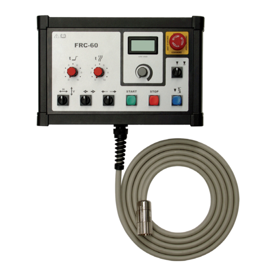
Page 21: Control Elements And Connections
(11) START STOP (10) FRC-60 control panel (1) Traverse speed digital indicator ... indicates the current traverse speed of the tripod unit in cm/min. The digital display has green background lighting which is permanently on. Display unit: cm/ min Display range: 0.0 - 99.9... - Page 22 FRC-60 remote (5) Pneumatic system on/off button control, front ... in order for a pneumatic unit to raise or lower the torch (pneumatic torch lowering). view The button will be lit when this function is activated. (continued) Important! Press "Stop" button when welding torch is lowered to preselect the welding process.
-
Page 23: Frc-60 Remote Control, Rear View
FRC-60 remote control, rear view FRC-60 rear view (1) remote control holder ... for attaching the remote control to the remote control holder on the tripod. (2) Cable gland ... Cable gland with strain relief device and anti-kink protection. (3) Connecting plug with cable ... -
Page 24: Commissioning
Connecting the Important! The connection socket for the remote control FRC-60 remote control is located on the underside of the tripod unit control box. 1. Connect the remote control plug to the connecting socket on the tripod unit control box. -
Page 25: Switch On System Components
NOTE! The workpiece must be aligned and located in its welding position. welding torch You should check this before positioning the torch. Use the FRC-60 remote control for the positioning operation: 1. Configure the following tripod unit settings: Traverse axis... -
Page 26: Lowering And Setting Up The Welding Torch
Positioning the 3. Switch over the "H/V axis" selector switch. The opposite axis will now be activated. welding torch (continued) 4. Press the MANUAL MOVE button and continue the positioning process. Continue positioning the welding torch using the respective axes until it is correctly positioned. -
Page 27: Loading A Welding Program
(JOB number). These programs can be reloaded at any time, and corrected as required. The programs are managed from the power source control panel. Defining parame- The following parameters should be defined on the FRC-60 remote control for the weld- ters for the tripod ing process: unit... -
Page 28: Carrying Out A Test Run
Avoid contact with these machine parts 1. Turn the Welding ON/OFF selector switch to OFF 2. Press START button on FRC-60 remote control. To stop the process early press the STOP button. Important! If an offset welding axis is used, start the test run by pressing the START button on the rotary unit controller. -
Page 29: Troubleshooting
In the event of faults, note that the function of the entire system depends on many ad- ditional components that are also potential sources of problems. NOTE! Repairs may only be carried out by qualified experts or by Fronius serv- ice personnel. -
Page 30: Possible Errors In "Offset Welding Axis" Application
Possible errors Tripod unit moves but arc does not ignite in "Welding axis" After the START button is pressed, the tripod unit carries out the welding movement but application the arc does not ignite (continued) Cause: welding is deactivated (test mode) Remedy: Turn the Welding ON/OFF selector switch to ON Cause:... -
Page 31: Technical Data
65 mm 55 mm Weight 2 kg Connecting cable length No. of pins on connecting plug Suitable types of tripod unit FTU 900-500 FTU 900-1000 FTU 1200-1000 FTU 1600-1500 FRC-60 cm/ min START STOP FRC-60 remote control, dimensions 29 / 35... -
Page 32: Spare Parts Overview
Spare parts overview 14.1 15.1 14.2 15.2 14.3 15.3 FRC-60 cm/ min 13.1 13.2 13.3 START STOP 12.1 11.1 10.1 Spare parts for FRC-60 remote control 30 / 35... -
Page 33: Ordering Details
NOTE! Only trained technicians may change parts and may only do so after having read the installation and dismantling instructions supplied. When ordering spare parts for the FRC-60 remote control you should provide the follow- ing data: Exact designation of the spare part... -
Page 34: Circuit Diagrams
Circuit diagrams 32 / 35... - Page 35 33 / 35...
- Page 36 34 / 35...
-
Page 37: Eu-Declaration Of Conformity
EU-Declaration of conformity 35 / 35... - Page 38 FRONIUS INTERNATIONAL GMBH TechSupport Automation E-Mail: support.automation@fronius.com www.fronius.com www.fronius.com/addresses...
Need help?
Do you have a question about the FRC-60 and is the answer not in the manual?
Questions and answers