Table of Contents
Advertisement
Quick Links
Download this manual
See also:
User Manual
Advertisement
Table of Contents

Related Manuals for Winmate EAC Mini EACIL20


Summary of Contents for Winmate EAC Mini EACIL20
- Page 1 IoT Gateway Intel® Apollo Lake N3350, 1.1 GHz Intel® Apollo Lake N4200, 1.1 GHz (Option) EAC Mini EACIL20 User Manual Document Version 1.3 Document Part Number : 91711110100O Please read these instructions carefully before using this product, and save this manual for future use.
-
Page 3: Table Of Contents
EAC Mini EACIL20 IoT Gateway User Manual Contents Preface .......................... 3 About This User Manual ....................7 Chapter 1: Introduction ....................8 1.1 Overview ......................9 1.2 Product Features ....................9 1.3 Expansion Module ....................9 1.3 Hardware Specifications ..................10 1.4 Package Contents .................... - Page 4 Preface 4.2.5 Power Menu ..................... 47 4.2.3 Boot Menu ....................50 4.2.3 Exit Menu ....................52 4.3 Using Recovery Wizard to Restore Computer ............ 53 4.4 How to Enable Watchdog ................... 54 Chapter 5: Driver Installation ..................55 5.1 Chipset Driver Installation .................. 56 5.2 Graphic Driver Installation ..................
-
Page 5: Preface
EAC Mini EACIL20 IoT Gateway User Manual Preface Copyright Notice No part of this document may be reproduced, copied, translated, or transmitted in any form or by any means, electronic or mechanical, for any purpose, without the prior written permission of the original manufacturer. - Page 6 Preface Customer Service We provide a service guide for any problem by the following steps: First, visit the website of our distributor to find the update information about the product. Second, contact with your distributor, sales representative, or our customer service center for technical support if you need additional assistance.
- Page 7 EAC Mini EACIL20 IoT Gateway User Manual Safety Information Warning! Always completely disconnect the power cord from your chassis whenever you work with the hardware. Do not make connections while the power is on. Sensitive electronic components can be damaged by sudden power surges.
- Page 8 Preface Important Information Federal Communications Commission Radio Frequency Interface Statement This device complies with part 15 FCC rules. Operation is subject to the following two conditions: This device may not cause harmful interference. This device must accept any interference received including ...
-
Page 9: About This User Manual
The documentation set for the Winmate® EAC Mini EACIL20 IoT Gateway provides information for specific user needs, and includes: EAC Mini EACIL20 Quick Start Guide - describes how to get the box computer up and running. EAC Mini EACIL20 User Manual – contains detailed description on how to use the display, its components and features. -
Page 10: Chapter 1: Introduction
Chapter 1: Introduction Chapter 1: Introduction This chapter provides the EAC Mini EACIL20 IoT Gateway product overview, describes its features and hardware specifications. -
Page 11: Overview
1.1 Overview Congratulations on purchasing Winmate® EAC Mini EACIL20 IoT Gateway The EAC Mini EACIL20 is a compact industrial IoT Gateway with low power consuming Intel® Apollo Lake processor. The EAC Mini provides great expansion including one Mini-PCIe and SIM card support. -
Page 12: Hardware Specifications
Chapter 1: Introduction 1.3 Hardware Specifications Model Name EACIL20 Intel® Apollo Lake N3350 1.1 GHz Intel® Apollo Lake N4200, 1.1 GHz (Option) Graphics Intel® HD Graphics Engine System BIOS Insyde UEFI Specification Watchdog Programmable 256 levels, timer interval 1 to 255 sec. Timer Technology 4GB LPDDR3 1866MHz... -
Page 13: Package Contents
EAC Mini EACIL20 IoT Gateway User Manual 1.4 Package Contents Carefully remove the box and unpack EAC Mini EACIL20 IoT Gateway. Please check if all the items listed below are inside your package. If any of these items are missing or damaged contact us immediately. -
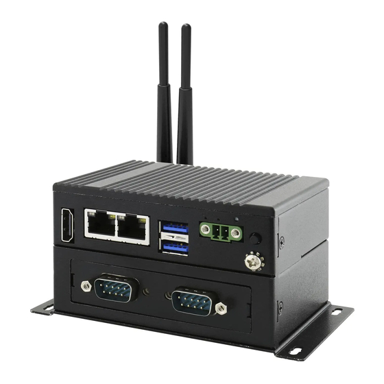
Page 14: Description Of Parts
Chapter 1: Introduction 1.5 Description of Parts This section includes front and rear side I/O ports location of the EAC Mini EACIL20 IoT Gateway. Front Side Rear Side 1.6 LED Indicators The EAC Mini IoT Gateway provides one HDD and one Power LED indicators located on the front for status monitoring. -
Page 15: Mechanical Dimensions
EAC Mini EACIL20 IoT Gateway User Manual 1.7 Mechanical Dimensions All dimensions are shown in mm (millimeters). Unit without mounting bracket Standard With Expansion Module Unit with mounting bracket... -
Page 16: Chapter 2: Hardware Installation
Chapter 2: Hardware Installation Chapter 2: Hardware Installation This chapter provides information on how to use external I/O and the installation of EAC Mini EACIL20 IoT Gateway hardware. -
Page 17: Connectors
The following sections give you information about EAC Mini standard connectors and pin assignments. 2.1.1 HDMI Connector Plug HDMI signal cable to the HDMI connector of the EAC Mini EACIL20, and plug the other end to the monitor. Pin assignment and signal names of HDMI connector Pin №... -
Page 18: Usb Connector
Chapter 2: Hardware Installation 2.1.3 USB Connector The EAC Mini EACIL20 provides two USB 3.0 connectors. Use USB 3.0 connector to connect external devices such as mouse or keyboard to the box computer. Pin assignment and signal names of USB connector Pin №... -
Page 19: External Antenna Installation
EAC Mini EACIL20 IoT Gateway User Manual 2.2.2 External Antenna Installation Notice that external antenna is an optional feature of the EAC Mini EACIL20. To install external SMA antenna: 1. Remove the rubber cap on the SMA connector before installing the antenna. -
Page 20: Expansion Module Installation
Chapter 2: Hardware Installation 2.2.3 Expansion Module Installation Notice that expansion module is an optional feature of the EAC Mini EACIL20. To install expansion module: Unscrew the three screws, and remove Attach the 2 layer module bracket and install ❶... -
Page 21: Usb Wire Loop Installation
EAC Mini EACIL20 IoT Gateway User Manual 2.2.4 USB Wire Loop Installation To install USB Wire Loop: ❶ Insert USB to the USB slot. ❷ Install copper pillar, USB wire loop, and fasten one screw to secure the USB to the EAC Mini EACIL20. -
Page 22: Connecting The Power
Chapter 2: Hardware Installation 2.3 Connecting the Power The DC power supply connector of the EAC Mini IoT Gateway is on the front panel. The DC power input for the EAC Mini allows a voltage input range from 9 V DC to 36 V DC. Warning! Ensure voltage and polarity is compliant with the DC input. -
Page 23: Chassis Grounding
EAC Mini EACIL20 IoT Gateway User Manual 2.3.2 Chassis Grounding EAC Mini provides EMI protection and a stable grounding base. Use chassis grounding point located on the front. -
Page 24: Chapter 3: Mounting
Chapter 3: Mounting Chapter 3: Mounting The EAC Mini supports five types of mounting: wall and desk mounting by default, and optional VESA, DIN-rail mounting solutions. You can purchase mounting kit from Winmate as an optional accessory. -
Page 25: Wall/ Desk Mount
EAC Mini EACIL20 IoT Gateway User Manual 3.1 Wall/ Desk Mount L-shape mounting brackets for wall/ desk mounting are supplied with the EAC Mini. Before mounting the unit to the wall, attach L-shape mounting brackets to the EAC Mini (supplied by Winmate). -
Page 26: Din-Rail Mount
Chapter 3: Mounting 3.2 DIN-Rail Mount You can purchase DIN-Rail mounting kit from Winmate as an optional accessory. DIN-Rail Mounting Kit: Part Number: 821118551400 Mounting Instruction: ❶ Fasten screws to secure DIN-rail ❷ Place the EAC Mini with the DIN-Rail mounting bracket to the EAC Mini. -
Page 27: Vesa Mount
EAC Mini EACIL20 IoT Gateway User Manual 3.3 VESA Mount You can purchase VESA mounting kit from Winmate as an optional accessory. VESA Mounting Kit Part Number: 821118561001 Mounting Instruction: ❶ Mark the location of the screw holes on the ❷... -
Page 28: Chapter 4: Insyde Uefi Bios Setup
Chapter 4: Insyde UEFI BIOS Setup Chapter 4: Insyde UEFI BIOS Setup BIOS Setup Utility is a program for configuration basic Input / Output system settings of the computer for optimum use. This chapter provides information on how to use BIOS setup, its functions and menu. -
Page 29: How And When To Use Bios Setup
EAC Mini EACIL20 IoT Gateway User Manual 4.1 How and When to Use BIOS Setup To enter the BIOS setup, you need to connect an external USB keyboard, external monitor and press Del key when the prompt appears on the screen during start up. The prompt screen shows only few seconds so need press Del key quickly. -
Page 30: Bios Functions
Chapter 4: Insyde UEFI BIOS Setup 4.2 BIOS Functions 4.2.1 Main Menu The Main menu displays the basic information about yoursystem including BIOS version, processor RC version, system language, time, and date. When you enter BIOS setup, the first menu that appears on the screen is the main menu.It contains the system information including BIOS version, processor RC version, system language, time, and date. -
Page 31: Advanced Settings
EAC Mini EACIL20 IoT Gateway User Manual 4.2.2 Advanced Settings Select the Advanced Tab from the setup menu to enter the advanced BIOS setup screen. You can select any of the items on the left frame of the screen to go to the sub menu for the item, such as CPU Configuration. - Page 32 Chapter 4: Insyde UEFI BIOS Setup 4.2.2.1 Boot Configuration BIOS Setting Description Setting Option Effect Select the OS of your OS Selection Windows/ Linux Select OS computer.
- Page 33 EAC Mini EACIL20 IoT Gateway User Manual 4.2.2.2 GOP and IGD Configuration...
- Page 34 Chapter 4: Insyde UEFI BIOS Setup BIOS Setting Description Setting Option Effect GOP Configuration Enable GOP Driver will Enabled unload VBIOS Use this item to enable or GOP Driver disable GOP Driver Disable It will load Disabled VBIOS IGD Configuration Use this item to enable or Integrated Graphics Enabled/...
- Page 35 EAC Mini EACIL20 IoT Gateway User Manual 4.2.2.3 Advanced Configuration BIOS Setting Description Setting Option Effect PCI Express Use this item to select PCI Enter Opens submenu Configuration Express paramerters Use this item to change SATA Drives Enter Opens submenu...
- Page 36 Chapter 4: Insyde UEFI BIOS Setup 4.2.2.3.1 PCI Express Configuration BIOS Setting Description Setting Option Effect PCI Express Clock Use this item to select PCI PCI Express Clock Enadbled/ Gating enable/ Express Clock Gating Gating Disabled disable for each root paramerters port PCIe Port Assigned...
- Page 37 EAC Mini EACIL20 IoT Gateway User Manual...
- Page 38 Chapter 4: Insyde UEFI BIOS Setup BIOS Setting Description Setting Option Effect PCI Express Active State Power Disabled/ L0s/ Set the parameters of ASPM Management setting L1/ L0sL1/ Auto ASPM Disabled/ L1.1/ PCI Express L1 Substate Set the parameters of L1 L1 Substates L1.2/ settings...
- Page 39 EAC Mini EACIL20 IoT Gateway User Manual 4.2.2.4 SATA Drives BIOS Setting Description Setting Option Effect The Chipset SATA Chipset-SATA controller supports the 2 Enables/ Disables the Controller black Internal SATA ports Enadbled/ Disabled Chipset-SATA Controller Configuration (up to 3 GBb/s supported...
- Page 40 Chapter 4: Insyde UEFI BIOS Setup 4.2.2.5 SCC Configuration BIOS Setting Description Setting Option Effect SCC SD Card Configure SCC SD Card Enadbled/ Enadble/ Disable SCC Support (D27:F0) Support settings Disabled SD Card Support SCC eMMC Configure SCC eMMC Enadbled/ Enadble/ Disable SCC Support (D28:F0) Support settings...
- Page 41 EAC Mini EACIL20 IoT Gateway User Manual 4.2.2.6 USB/ XHCI/ XDCI Configuration Setting BIOS Setting Description Effect Option Configure USB BIOS Enadbled/ USB/ keyboard/ mouse/ storage USB BIOS Support Support settings Disabled support under UEFI environment Configure XHCI Pre- Enadbled/...
- Page 42 Chapter 4: Insyde UEFI BIOS Setup 4.2.2.7 Miscellenaous Configuration Setting BIOS Setting Description Effect Option Configure High Precious Enadbled/ Enadble/ Disable XDCI High High Precious Timer Timer t settings Disabled Precious Event Timer Configure 8254 Clock Enadbled/ Enadble/ Disable 8254 Clock 8254 Clock Gating Gating settings Disabled...
- Page 43 EAC Mini EACIL20 IoT Gateway User Manual 4.2.2.8 TXE and TPM Configuration Setting BIOS Setting Description Effect Option Configure Target TPM Target TPM device fTPM/ dTPM Select fTPM or dTPM device settings...
- Page 44 Chapter 4: Insyde UEFI BIOS Setup 4.2.2.9 Thermal Configuration Parameters Setting BIOS Setting Description Effect Option Configure _CTR, _PSV, and _ACO automatically based Enabled/ Automatic Thermal on values recommended in Set to Disabled for manual BWG’s Thermal Reporting Disabled Reporting configuration for Thermal Management settings...
- Page 45 EAC Mini EACIL20 IoT Gateway User Manual 4.2.2.10 WDT Configuration Setting BIOS Setting Description Effect Option Enabled/ Configure WDT settings Enable/Disable WDT Disabled Check Hardware Monitor Hardware Monitor Press Enter Open sub-menu settings GPIO Group 0 Check GPIO Group 0...
- Page 46 Chapter 4: Insyde UEFI BIOS Setup Hardware Monitor GPIO Group 0 Configuration BIOS Setting Description Setting Option Effect User can pull internal Push Pull/ Internal Resistance resistance push-pull/ open- Set Push Pull or Open Drain Open Drain drain Set the GPIO is input or Set the GPIO is input or Input/ Output Mode Input/ Output...
- Page 47 EAC Mini EACIL20 IoT Gateway User Manual 4.2.2.11 H2oUve Setup Setting BIOS Setting Description Effect Option Enable/ Disable Interface Enabled/ Enable/ Disable H2oUve H2oUve Support Disabled for H2oUve tool Support...
-
Page 48: Security Menu
Chapter 4: Insyde UEFI BIOS Setup 4.2.4 Security Menu This section allows to configure and improve system, and set up some system features according to your preferences. Setting BIOS Setting Description Effect Option TrEE Protocol Select TrEE Protocol Select TrEE Protocol 1.0/ 1.1 Version Version: 1.0 or 1.1... -
Page 49: Power Menu
EAC Mini EACIL20 IoT Gateway User Manual 4.2.5 Power Menu BIOS Setting Description Setting Option Effect CPU Configuration Check CPU Configuration Press Enter Opens sub-menu 4.2.5.1 CPU Configuration... - Page 50 Chapter 4: Insyde UEFI BIOS Setup BIOS Setting Description Setting Option Effect When a processor If bi-direction is enabled, thermal sensor trips Enabled/ Bi-directional external agents can drive (either core) , the Disabled PROCHOT# PROCHOT# to throttle the PROCHOT# will be processor driven Enabled/...
- Page 51 EAC Mini EACIL20 IoT Gateway User Manual 4.2.5.2 System Power Options Setting BIOS Setting Description Effect Option Allows more than two Enabled/ Enable/ Disable Intel® Intel® SpeedStep frequency range to be Disabled (tm) SpeedStep (tm) supported Configure Boot Select the performance state...
-
Page 52: Boot Menu
Chapter 4: Insyde UEFI BIOS Setup 4.2.3 Boot Menu... - Page 53 EAC Mini EACIL20 IoT Gateway User Manual Setting BIOS Setting Description Effect Option Configure Boot Type Dual / Legacy/ Select boot type to Dual, Legacy Boot Type settings UEFI or UEFI type Allows InsideH20 to skip certain Enabled/ Configure Quick Boot tests while booting.
-
Page 54: Exit Menu
Chapter 4: Insyde UEFI BIOS Setup 4.2.3.1 Boot Type Order 4.2.3 Exit Menu... -
Page 55: Using Recovery Wizard To Restore Computer
EAC Mini EACIL20 IoT Gateway User Manual 4.3 Using Recovery Wizard to Restore Computer Note: Before starting the recovery process, make sure to backup all user data. The data will be lost after the recovery process. Important: Before starting the recovery process, remove the PCI/ PCIe card and CFast card. -
Page 56: How To Enable Watchdog
Chapter 4: Insyde UEFI BIOS Setup 4.4 How to Enable Watchdog To enable Watchdog, you need to download Winmate Watchdog utility. Find more information on Watchdog in “Watchdog Guide” that you can download from Winmate Download Center. To enable watchdog in Watchdog AP follow the instructions below: 1. -
Page 57: Chapter 5: Driver Installation
Chapter 5: Driver Installation Chapter 5: Driver Installation This chapter provides instructions on how to install drivers on the EAC Mini IoT Gateway. Notice that pictures in this example are for Windows 10 OS. -
Page 58: Chipset Driver Installation
Chapter 5: Driver Installation 5.1 Chipset Driver Installation To install chipset driver: 1. Open the driver CD and double-click on Chipset driver. 2. The system opens installation window, click Next to continue. - Page 59 EAC Mini EACIL20 IoT Gateway User Manual 3. Click Accept to agree to the license terms. 4. Check installation details and click Install. 5. The installation is complete, click Finish to exit installation window.
-
Page 60: Graphic Driver Installation
Chapter 5: Driver Installation 5.2 Graphic Driver Installation To install graphic driver: 1. Open the driver CD and double-click on Graphic driver. 2. The system opens installation window, click Next to continue. - Page 61 EAC Mini EACIL20 IoT Gateway User Manual 3. Click Accept to agree to the license terms. 4. Check installation details and click Install. 5. Wait for the system to install the driver. 6. The installation is complete, click Next to continue.
- Page 62 Chapter 5: Driver Installation 7. Select Accept, and exit installation window.
-
Page 63: Txe (Trusted Execution Engine) Driver Installation
EAC Mini EACIL20 IoT Gateway User Manual 5.3 TXE (Trusted Execution Engine) Driver Installation To install TXE (Trusted Execution Engine) driver: 1. Open the driver CD and double-click on TXE driver. 2. The system opens installation window, click Next to continue. - Page 64 Chapter 5: Driver Installation 3. Click Next to agree to the license terms. 4. Check installation details and click Next. 5. Wait for the system to install the driver.
- Page 65 EAC Mini EACIL20 IoT Gateway User Manual 6. The installation is complete, click Finish to exit installation window.
-
Page 66: Serial Io Driver Installation
Chapter 5: Driver Installation 5.4 Serial IO Driver Installation To install Serial IO driver: 1. Open the driver CD and double-click on Serial IO driver. 2. The system opens installation window, click Next to continue. - Page 67 EAC Mini EACIL20 IoT Gateway User Manual 3. Click Accept to agree to the license terms. 4. Check installation details and click Install. 5. Click Next to continue. 6. Wait for the system to install the driver.
- Page 68 Chapter 5: Driver Installation 7. The installation is complete, click Finish to exit installation window.
-
Page 69: Lan Driver Installation
EAC Mini EACIL20 IoT Gateway User Manual 5.5 LAN Driver Installation To install LAN driver: 1. Open the driver CD and double-click on LAN driver. 2. The system opens installation window. - Page 70 Chapter 5: Driver Installation 3. Click Next to continue. 4. Press Next to continue. 5. Press Next to continue. 6. Press Install.
- Page 71 EAC Mini EACIL20 IoT Gateway User Manual 7. Wait for the system to install driver. 8. The installation is complete, click Finish to exit installation window.
-
Page 72: Chapter 6: Technical Support
Chapter 6: Technical Support Chapter 6: Technical Support This chapter includes pathway for technical support and Software Development Kit (SDK). Free technical support is available from our engineers every business day. We are always ready to give advice on application requirements or specific information on the installation and operation of any of our products. -
Page 73: Software Developer Support
Chapter 6: Technical Support 6.1 Software Developer Support You can download SDK, derivers and other document from Winmate Download Center Winmate File Share. Winmate Download Center http://www.winmate.com/ > Support > Download Center > Embedded Computing > EAC Mini EACIL20 6.2 Problem Report Form... -
Page 74: Appendix
EAC Mini EACIL20 IoT Gateway User Manual Appendix This chapter provides additional information about EAC Mini EACIL20 IoT Gateway. -
Page 75: Appendix A: Order Information
Appendix Appendix A: Order Information EAC Mini EACIL20 IoT Gateway available in the following configurations: Model Name Configuration EACIL20-100-A432 Intel N3350, 4G RAM, 32GB eMMC, 2 x USB 3.0, 2 x GbE LAN, 1 x HDMI EACIL20-101-A432 Intel N3350, 4G RAM, 32GB eMMC, 2 x USB 3.0,... -
Page 76: Appendix B: Expansion Module
Appendix Appendix B: Expansion Module 16-Channel Digital I/O with isolation EACWLST-232 To install EACWLST-232 module: Chapter 2, “Expansion Module Installation” 1. Follow the procedure described in to install EACWLST-232 module. 2. Connect two USB cables. One end to EACWLST-232 board and another end to EAC Mini motherboard. -
Page 77: 2- Port Canbus With Isolation Eacwlst-233
EAC Mini EACIL20 IoT Gateway User Manual 2- Port CANBus with isolation EACWLST-233 To install EACWLST-233 module: Chapter 2, “Expansion Module Installation” 4. Follow the procedure described in to install EACWLST-233 module. 5. Connect two USB cables. One end to EACWLST-233 board and another end to EAC Mini motherboard. -
Page 78: 2-Port Giga-Lan Eacwlst-236
Appendix 2-port Giga-LAN EACWLST-236 To install EACWSLT-236 module: Chapter 2, “Expansion Module Installation” 1. Follow the procedure described in to install EACWSLT-236 module. 2. Connect two USB cables. One end to EACWSLT-236 board and another end to EAC Mini motherboard. 3. -
Page 79: 2-Port Rs232/422/485 With Isolation Eacwlst-235 & Eacwlst-231
EAC Mini EACIL20 IoT Gateway User Manual 2-Port RS232/422/485 with isolation EACWLST-235 & EACWLST-231 To install EACWLST-235 module: Chapter 2, “Expansion Module Installation” 1. Follow the procedure described in to install EACWLST-235 module. 2. Connect one end of the USB cable to the EACWLST-235 board and another end to the EAC Mini motherboard. - Page 80 Winmate Inc. 9F, No.111-6, Shing-De Rd., San-Chung District, New Taipei City 24158, Taiwan, R.O.C www.winmate.com Copyright © Winmate Inc. All rights reserved.
Need help?
Do you have a question about the EAC Mini EACIL20 and is the answer not in the manual?
Questions and answers