
Related Manuals for Wacker Neuson BPU 2440 series


Summary of Contents for Wacker Neuson BPU 2440 series
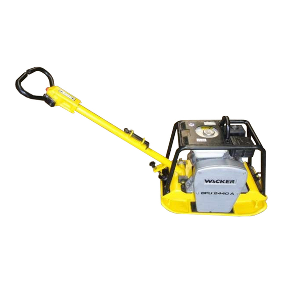
- Page 1 www.wackergroup.com 0078232 0603 Vibroplate BPU 2440 BPU 2950 REPAIR MANUAL...
- Page 3 BPU 2440/2950 Repair Foreword This manual covers machines with Item Number: 5603, 5904, 6222, 6346, 6412, 6993, 7150, 7867, 7872, 7962 Operating / Parts Information You must be familiar with the operation of this machine before you attempt to troubleshoot or make any repairs to it. Basic operating and maintenance procedures are described in the operator’s / parts manual supplied with the machine.
- Page 4 Foreword BPU 2440/2950 Repair CALIFORNIA Proposition 65 Warning: Engine exhaust, some of its constituents, and certain vehicle components contain or emit chemicals known to the State of California WARNING to cause cancer and birth defects or other reproductive harm. All rights, especially copying and distribution rights, are reserved. Copyright 2003 by Wacker Corporation.
-
Page 5: Table Of Contents
Table of Contents Safety Information Operating Safety .................. 4 Operator Safety while using Internal Combustion Engines ....5 Service Safety ..................5 Labels ....................7 Technical Data Engine ....................9 Plate ..................... 9 Lubrication ..................10 Dimensions ..................10 General Information Application .................. - Page 6 Table of Contents Carburetor Adjustment ................25 Drive Belt .....................26 Exciter Oil ....................27 4.10 Control Circuit Oil ................27 4.11 Bleeding the Control Circuit ..............28 4.12 Re-installing Piston in Control Assembly ..........29 Repair Procedures General Repair ..................30 Checking Exciter Operation ..............31 Exciter Exploded View Illustration ............32 Exciter Parts List .................33 Removing Exciter ................34 Installing Exciter ..................35...
-
Page 7: Safety Information
BPU 2440/2950 Repair Safety Information Safety Information This manual contains DANGER, WARNING, CAUTION, and NOTE callouts which must be followed to reduce the possibility of personal injury, damage to the equipment, or improper service. This is the safety alert symbol. It is used to alert you to potential personal injury hazards. -
Page 8: Operating Safety
Safety Information BPU 2440/2950 Repair Operating Safety Familiarity and proper training are required for the safe operation of equipment! Equipment operated improperly or by untrained personnel can be dangerous! Read the operating instructions contained in both WARNING this manual and the engine manual and familiarize yourself with the location and proper use of all controls. -
Page 9: Operator Safety While Using Internal Combustion Engines
BPU 2440/2950 Repair Safety Information Operator Safety while using Internal Combustion Engines Internal combustion engines present special hazards during operation and fueling! Read and follow warning instructions in engine owner's manual and safety guidelines below. Failure to follow warnings and DANGER safety guidelines could result in severe injury or death. - Page 10 Safety Information BPU 2440/2950 Repair 1.3.6 DO NOT crank a flooded engine with the spark plug removed on gasoline-powered engines. Fuel trapped in the cylinder will squirt out the spark plug opening. 1.3.7 DO NOT test for spark on gasoline-powered engines, if engine is flooded or the smell of gasoline is present.
-
Page 11: Labels
BPU 2440/2950 Repair Safety Information Labels Label Meaning DANGER! Engines emit carbon monoxide; operate only in well ventilated area. Read the operator's manual. No sparks, flames or burning objects near machine. Shut off engine before refueling. WARNING! Hot surface. CAUTION! Read and understand the supplied operator's manuals before operating this machine. - Page 12 Safety Information BPU 2440/2950 Repair Label Meaning WARNING! To prevent hearing loss, wear hearing protec- tion when operating this machine. wc_gr001475 A nameplate listing the Model Number, Item Number, Revision, and Serial Number is attached to each unit. Please record the infor- mation found on this plate so it will be avail- able should the nameplate become lost or damaged.
-
Page 13: Technical Data
BPU 2950/2440 Repair Technical Data Technical Data Engine Model 2440A 2440A 2950R 2950R 2950A 2440A 7150 7867 5603 6222 6412 5904 6346 6993 7872 7962 Engine Engine Make Honda Honda Robin Robin Honda Engine Model GX 140 GX 160 EY 27W W1-280 GX 240 Rated Power... -
Page 14: Lubrication
Technical Data BPU 2950/2440 Repair Lubrication Engine Exciter Model Quantity Quantity Oil Grade Oil Grade (S/N) ml (ounces) ml (ounces) BPU 2440A 10W40 600 (20) (5904) BPU 2440A 10W30 600 (20) (7150) BPU 2440A 10W30 600 (20) (7867) SAE 15W40 750 (25) BPU 2650R 10W030... -
Page 15: General Information
BPU 2440/2950 Repair General Information General Information Application Due to its low width of only 400 or 500 mm and its infinitely variable working speed setting, this vibratory plate is particularly suited for all kinds of soil compaction in confined areas such as in cable trenches 40 cm wide or more, compaction of marginal strips, repairs on blacktop surfaces as well as for all compaction jobs where the use of large scale equipment is not suitable. -
Page 16: Reference Numbers ( )
General Information BPU 2440/2950 Repair Reference Numbers ( ) Repair procedures contain reference numbers enclosed parentheses ( ). These numbers refer to the item numbers shown on the assembly drawings and other detailed drawings. They are included to aid the mechanic in identifying parts and assembling components. Weight Block See Graphic: wc_gr000843 The weight block symbol gives an approximate weight measurement... -
Page 17: Storage
BPU 2440/2950 Repair General Information Never lift or transport the machine with its engine running. Storage CAUTION Job Site Storage Never allow the machine to sit overnight in a ditch, trench, or other low area that may fill with water during heavy rain. CAUTION Long-term Storage Before storing the unit for a long period of time, be sure it is in good... -
Page 18: Theory Of Operation
General Information BPU 2440/2950 Repair Theory of Operation See Graphic: wc_gr000085 and wc_gr001430 The vibration required for compaction is produced by the exciter (a) which is firmly joined to the lower mass (b). The exciter contains two shafts with eccentric weights attached to each shaft. The shafts are connected by a sleeve gear and rotate in opposite directions. - Page 19 BPU 2440/2950 Repair General Information wc_gr001430 wc_gr000085 wc_tx000264gb.fm...
-
Page 20: Directional And Speed Control
General Information BPU 2440/2950 Repair Directional and Speed Control See Graphic: wc_gr001431 The control lever (a) operates a hydraulically actuated piston which connects to the sleeve gear inside the exciter. As the piston moves in and out, the sleeve gear rotates, changing the position of the eccentric weights (c) inside the exciter. - Page 21 BPU 2440/2950 Repair General Information ˚ ˚ ˚ wc_gr001431 wc_tx000264gb.fm...
-
Page 22: Engine Speed And Machine Performance
General Information BPU 2440/2950 Repair 3.10 Engine Speed and Machine Performance Even a small rise or fall in engine speed will affect the centrifugal force produced by the exciter. If the engine runs overspeed even slightly, the centrifugal force will increase significantly and overload the exciter bearings. -
Page 23: To Start
BPU 2440/2950 Repair General Information 3.12 To Start See graphic: wc_gr000014 3.12.1 Open fuel valve by moving lever to the right (a1). Note: If engine is cold, move choke lever to close position (b1) . If engine is hot, set choke to open position (b2 ) . 3.12.2 Turn engine switch to “ON”... -
Page 24: Maintenance
Maintenance BPU 2440/2950 Repair Maintenance General Maintenance Periodic maintenance is essential to prolong the service life of the plate and engine. Use the Maintenance Schedule as a guide when servicing the equipment. Compaction equipment is designed and manufactured to perform heavy work under harsh operating conditions. -
Page 25: Maintenance Schedule
BPU 2440/2950 Repair Maintenance Maintenance Schedule Daily Every Every Every before starting hrs. hrs. hrs. Check engine oil level. • Visually inspect exciter base for leaks. • Inspect/clean air filter. Re-oil foam element; • replace as required. Check/tighten external hardware. •... -
Page 26: Air Filter
Maintenance BPU 2440/2950 Repair Air Filter See graphic: wc_gr001432 4.3.1 Take off cover (a) and remove foam element (b). 4.3.2 Wash element with liquid detergent (c) and hot water. Rinse with clean water. Wrap in a clean towel and wring dry. Do not use gasoline, paint thinner, or other low flash point solvent for cleaning air cleaner element. -
Page 27: Spark Plug
BPU 2440/2950 Repair Maintenance Spark Plug See Graphic: wc_gr000028 Clean or replace spark plug as needed to ensure proper operation. Refer to the engine Owner’s Manual. The muffler becomes very hot during operation and remains hot for a while after stopping the engine. Do not touch the muffler while it is hot. WARNING Note: Refer to the Technical Data for the recommended spark plug type and the electrode gap setting. -
Page 28: Cleaning Sediment Cup
Maintenance BPU 2440/2950 Repair Cleaning Sediment Cup See Graphic: wc_gr000029 4.5.1 Turn fuel valve off. 4.5.2 Remove sediment cup (a) and O-ring (b). 4.5.3 Wash both thoroughly in a nonflammable solvent. Dry and reinstall them. 4.5.4 Turn fuel valve on and check for leaks. wc_tx000328gb.fm... -
Page 29: Adjusting Idle Speed
BPU 2440/2950 Repair Maintenance Adjusting Idle Speed See Graphic: wc_gr001122 Adjust engine to the no load or idle speed per the Technical Data. 4.6.1 Start the engine and allow it to warm up to normal operating temperature. 4.6.2 Turn the throttle stop screw (a) in to increase speed, out to decrease speed. -
Page 30: Drive Belt
Maintenance BPU 2440/2950 Repair Drive Belt See graphic: wc_gr00143 Recommended tools: Allen wrench—6 mm, Socket wrench—13 mm See Maintenance Schedule for service intervals. On new machines or after installing a new belt, check the belt tension after the first 5 hours of operation. -
Page 31: Exciter Oil
BPU 2440/2950 Repair Maintenance Exciter Oil See graphic: wc_gr001152 The bearings in the exciter assembly are splash lubricated and rotate at a very high speed (up to 5400 rpm). It is important to maintain the exciter oil at the proper level and change it regularly to ensure maximum protection. -
Page 32: Bleeding The Control Circuit
Maintenance BPU 2440/2950 Repair 4.11 Bleeding the Control Circuit See graphic: wc_gr001435 Recommended Tools: Allen wrench – 6 mm Socket or box wrench – 7 mm, 22 mm Bleed control circuit whenever handle or exciter have been opened for service. 4.11.1 Turn off engine before servicing. -
Page 33: Re-Installing Piston In Control Assembly
BPU 2440/2950 Repair Maintenance "OEL" 45˚ 90˚ wc_gr001435 Ref. Description Ref. Description Fill Plug O-Ring Spring Seal Piston O-Ring 4.12 Re-installing Piston in Control Assembly See graphic: wc_gr001435 If it is ever necessary to re-install the piston into the control assembly, carry out the following procedure. -
Page 34: Repair Procedures
Repair Procedures BPU 2440/2950 Repair Repair Procedures General Repair The repair procedures specify using sealants and screw and nut adhesives to seal metal surfaces and secure fasteners in place. These products must be used where indicated. Although Loctite is referred to throughout this manual, an equivalent sealant such as Hernon or Omnifit may be used. -
Page 35: Checking Exciter Operation
BPU 2440/2950 Repair Repair Procedures Checking Exciter Operation Before servicing the exciter, check for other possible problems that could affect machine operation, such as: engine speed, control circuit operation, drive belt tightness, and clutch performance. If the engine is running underspeed, the exciter VPM will be reduced, the plate will handle sluggishly and perform poorly, and travel speeds will be greatly reduced. -
Page 36: Exciter Exploded View Illustration
Repair Procedures BPU 2440/2950 Repair Exciter Exploded View Illustration wc_gr001436 wc_tx000329gb.fm... -
Page 37: Exciter Parts List
BPU 2440/2950 Repair Repair Procedures Exciter Parts List See graphic: wc_gr001436 Ref. Description Ref. Description Exciter housing Idler gear Screw M10x120 Idler shaft Screw M10x35 Eccentric weight Bearing (inner & outer race) Washer Bleed screw M4x5 Screw M10x35 Flanged cover Retaining ring Flanged cover Wear ring... -
Page 38: Removing Exciter
Repair Procedures BPU 2440/2950 Repair Removing Exciter See graphic: wc_gr001347 Recommended Tools: Socket wrench – 19 mm Allen wrench – 6 mm, 8 mm Open-end wrench – 17 mm, 19 mm Locking pliers 3-jaw puller Rubber mallet High-strength thread locking adhesive Gasket eliminator 5.5.1 Turn machine’s engine off. -
Page 39: Installing Exciter
BPU 2440/2950 Repair Repair Procedures Installing Exciter See graphic: wc_gr001441 5.6.1 Scrape off old gasket material and thoroughly clean mounting surfaces on exciter and baseplate. 5.6.2 Once thoroughly clean and completely dry, coat mounting baseplate (a) with Loctite 515 gasket eliminator or equivalent. 5.6.3 Position exciter assembly so that exciter drive pulley faces front right corner (b) of plate. -
Page 40: Exciter Assembly Cross Section
Repair Procedures BPU 2440/2950 Repair Exciter Assembly Cross Section wc_gr001442 wc_tx000329gb.fm... -
Page 41: Exciter Cross Section List Of Components
BPU 2440/2950 Repair Repair Procedures Exciter Cross Section List of Components See Graphic: wc_gr001442 Ref. Description Ref. Description Flange cover Piston assembly Idler shaft Piston seal Holder Eccentric weight bolt (2) Shaft seal Flanged cover bolt (2) Drive shaft Roller bearing Vent plug Retaining ring Retaining ring... -
Page 42: Servicing Exciter
Repair Procedures BPU 2440/2950 Repair Servicing Exciter Recommended Tools Allen wrench – 5 mm, 8 mm Snap ring pliers – external type Torque wrench – 38 ft.lbs. (50 Nm) Screwdriver Rubber mallet Arbor press Wooden V-block Loctite sealants – 242, 271, 515 5.10 Disassembling the Exciter See graphics: wc_gr001443, wc_gr001444, wc_gr001445 Refer to Cross Section Component List for item numbers ( ). - Page 43 BPU 2440/2950 Repair Repair Procedures 5.10.7 Remove piston assembly (15) from drive shaft by placing on a wooden V-block (c). The block should have a hole drilled in it for the guide pin (11). Press guide pin (d) (DO NOT HAMMER) through shaft until piston (e) can be removed.
-
Page 44: Re-Assembling The Exciter
Repair Procedures BPU 2440/2950 Repair 5.11 Re-assembling the Exciter Refer to Cross Section Component List for item numbers ( ). See graphics: wc_gr001446 and wc_gr001447 When installing shafts, make sure drive shaft is installed on machined end of housing. Later housings are symmetrical and are machined at all four bearing locations. - Page 45 BPU 2440/2950 Repair Repair Procedures wc_gr001447 wc_gr001446 Ref. Note Drive shaft side machined surface Pulley end of housing Piston end of housing Use flanged covers to position bearings the cor- rect distance into exciter housing. Procedure continued on next page. wc_tx000329gb.fm...
- Page 46 Repair Procedures BPU 2440/2950 Repair Timing Exciter Weights Refer to Cross Section Component List for item numbers ( ). See graphics: wc_gr001448, wc_gr001449, and wc_gr001450. 5.11.9 Align timing marks on gears with piston extended. View shafts from piston side and compare position of bolt holes in shafts and timing marks on gears with those shown.
- Page 47 BPU 2440/2950 Repair Repair Procedures wc_gr001449 wc_gr001448 wc_gr001450 Ref. Note Bolt holes must face timing mark with piston extended. Piston Position of exciter weights, piston fully extended. View from piston side. Timing marks Apply gasket eliminator to flange. Idler shaft Drive shaft wc_tx000329gb.fm...
-
Page 48: Servicing The Clutch
Repair Procedures BPU 2440/2950 Repair 5.12 Servicing the Clutch See graphic: wc_gr001470 The engine clutch is keyed (a) to the engine drive shaft (b) and secured using a washer and hex screw. To replace clutch shoes or springs: 5.12.1 Remove snap ring (c) that secures bearing (d) to hub (e). 5.12.2 Pry behind clutch drum and rap center bolt with rubber mallet until the drum and bearing are free from hub. -
Page 49: Replacing The Engine
BPU 2440/2950 Repair Repair Procedures 5.13 Replacing the Engine Wacker BPU series reversible vibroplates are powered by Robin or Honda engines in either 5.0, 5.5, or 8 hp models. Replacing the engine is similar for either type of engine; however, there are subtle differences. -
Page 50: Engine Replacement-Honda
Repair Procedures BPU 2440/2950 Repair 5.14 Engine Replacement—Honda See graphic: wc_gr001471 5.14.1 Using an appropriate hoist or crane to lift engine, place the engine on the upper mass and secure the engine with the four mounting bolts (a). Torque the bolts to 18 ft.lbs. (25 Nm) on BPU 2440A models; 36 ft.lbs. (49 Nm) on BPU 2950A models. -
Page 51: Engine Replacement-Robin
BPU 2440/2950 Repair Repair Procedures 5.15 Engine Replacement—Robin See graphic: wc_gr001472 The engine hardware is designed to provide clearance between the engine crankcase and the upper console. Any contact between the console and the engine may stress the engine block. There should be a small air gap between the engine and plate after hardware has been tightened. -
Page 52: Troubleshooting
Troubleshooting BPU 2440/2950 Repair Troubleshooting Problem Cause Remedy Engine runs, but no Belt broken or loose. Replace belt or adjust tension. vibration Clutch not engaging. Inspect clutch for damage and repair. Engine runs, but plate Engine RPM set too low. Adjust engine speed per manufacturer’s does not develop full recommendations. - Page 53 Threadlockers and Sealants Threadlockers and Sealants Threadlocking adhesives and sealants are specified throughout this manual by a notation of “S” plus a number (S#) and should be used where indicated. Threadlocking compounds normally break down at temperatures above 175°C (350°F). If a screw or bolt is hard to remove, heat it using a small propane torch to break down the sealant.
- Page 54 Threadlockers and Sealants TYPE PART NO. - ( ) = Europe COLOR USAGE SIZE Loctite Primer T Aerosol Fast curing primer for threadlocking, retaining and 2006124 - Hernon Primer 10 Spray sealing compounds. Must be used with stainless 6 oz. Omnifit VC Activator steel hardware.
- Page 55 Torque Values Torque Values Metric Fasteners (DIN) TORQUE VALUES (Based on Bolt Size and Hardness) WRENCH SIZE 10.9 12.9 Size ft.lb. ft.lb. ft.lb. Inch Metric Inch Metric 7/32 9/32 5/16 11/16 15/16 1-1/16 1-1/4 1 ft.lb. = 1.357 Nm. * = in.lb. 1 Inch = 25.4 mm...
- Page 56 Torque Values Inch Fasteners (SAE) Size ft.lb. ft.lb. ft.lb. Inch Metric Inch Metric No.4 3/32 No.6 5/16 7/64 No.8 11/32 9/64 No.10 5/32 7/16 3/32 5/16 9/16 5/16 7/16 9/16 13/16 15/16 1-1/8 1 ft.lb. = 1.357 Nm. * = in.lb. 1 Inch = 25.4 mm...
- Page 58 Wacker Construction Equipment AG · Preußenstraße 41 · D-80809 München · Tel.: +49-(0)89-354 02 - 0 · Fax: +49 - (0)89-354 02-390 Wacker Corporation · P.O. Box 9007 · Menomonee Falls, WI 53052-9007 · Tel. : +1-(1)(262) 255-0500 · Fax: +1-(1)(262) 255-0550 · Tel. : (800) 770-0957 Wacker Asia Pacific Operations ·...
Need help?
Do you have a question about the BPU 2440 series and is the answer not in the manual?
Questions and answers