Siemens SIMATIC ET 200MP User Manual
Interface module im 155-5 pn hf
Hide thumbs
Also See for SIMATIC ET 200MP:
- System manual (126 pages) ,
- Equipment manual (72 pages) ,
- Manual (60 pages)
Table of Contents
Advertisement
Quick Links
Advertisement
Table of Contents

Subscribe to Our Youtube Channel
Related Manuals for Siemens SIMATIC ET 200MP


Summary of Contents for Siemens SIMATIC ET 200MP
- Page 2 ___________________ Preface ___________________ Guide to documentation ___________________ SIMATIC Product overview ___________________ Wiring ET 200MP IM 155-5 PN HF Interface Module ___________________ (6ES7155-5AA00-0AC0) Parameter ___________________ Interrupts and diagnostic, error, and system alarms Manual ___________________ Technical specifications ___________________ Dimension drawing ___________________ Response times 10/2018 A5E32840985-AB...
- Page 3 Note the following: WARNING Siemens products may only be used for the applications described in the catalog and in the relevant technical documentation. If products and components from other manufacturers are used, these must be recommended or approved by Siemens. Proper transport, storage, installation, assembly, commissioning, operation and maintenance are required to ensure that the products operate safely and without any problems.
-
Page 4: Preface
Purpose of the documentation This manual supplements the system manual S7-1500, ET 200MP Automation system (https://support.industry.siemens.com/cs/ww/en/view/59191792). Functions that generally relate to the system are described in this manual. The information provided in this manual and in the system/function manuals supports you in commissioning the system. - Page 5 Siemens' products and solutions undergo continuous development to make them more secure. Siemens strongly recommends that product updates are applied as soon as they are available and that the latest product versions are used. Use of product versions that are no longer supported, and failure to apply the latest updates may increase customers' exposure to cyber threats.
-
Page 6: Table Of Contents
Table of contents Preface ..............................3 Guide to documentation .......................... 7 Product overview ..........................12 Properties ..........................12 Functions ..........................14 2.2.1 PROFINET IO ......................... 14 2.2.2 Configuration control (option handling) ................... 20 2.2.3 System redundancy on S7-400H .................... 20 Wiring .............................. -
Page 7: Guide To Documentation
Guide to documentation The documentation for the SIMATIC S7-1500 automation system and the SIMATIC ET 200MP distributed I/O system is arranged into three areas. This arrangement enables you to access the specific content you require. Basic information The System Manual and Getting Started describe in detail the configuration, installation, wiring and commissioning of the SIMATIC S7-1500 and ET 200MP systems. - Page 8 You must register once to use the full functionality of "mySupport". You can find "mySupport" on the Internet (https://support.industry.siemens.com/My/ww/en). "mySupport" - Documentation In the Documentation area in "mySupport" you can combine entire manuals or only parts of these to your own manual.
- Page 9 ● Manuals, characteristics, operating manuals, certificates ● Product master data You can find "mySupport" - CAx data on the Internet (http://support.industry.siemens.com/my/ww/en/CAxOnline). Application examples The application examples support you with various tools and examples for solving your automation tasks. Solutions are shown in interplay with multiple components in the system - separated from the focus on individual products.
- Page 10 You can find the SIMATIC Automation Tool on the Internet (https://support.industry.siemens.com/cs/ww/en/view/98161300). PRONETA With SIEMENS PRONETA (PROFINET network analysis), you analyze the PROFINET network during commissioning. PRONETA features two core functions: ● The topology overview independently scans PROFINET network and all connected components.
- Page 11 Guide to documentation SINETPLAN SINETPLAN, the Siemens Network Planner, supports you in planning automation systems and networks based on PROFINET. The tool facilitates professional and predictive dimensioning of your PROFINET installation as early as in the planning stage. In addition, SINETPLAN supports you during network optimization and helps you to exploit network resources optimally and to plan reserves.
-
Page 12: Product Overview
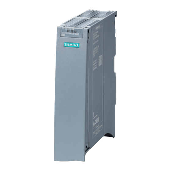
Product overview Properties Order number 6ES7155-5AA00-0AC0 View of the module Figure 2-1 View of the IM 155-5 PN HF interface module Properties ● Technical properties – Connects the ET 200MP distributed I/O system with PROFINET IO – 24 VDC supply voltage (SELV/PELV) –... - Page 13 (see relevant section in the system manual S7-1500, ET 200MP Automation system (https://support.industry.siemens.com/cs/ww/en/view/59191792)). ● A maximum of one power supply module (PS) upstream from the interface module and two downstream from the interface module is possible.
-
Page 14: Functions
Product overview 2.2 Functions Functions 2.2.1 PROFINET IO Introduction The interface module supports the following PROFINET IO functions: ● Integrated switch with 2 ports ● Supported Ethernet services: ping, arp, SNMP, LLDP ● Port diagnostics ● Deactivating ports ● Isochronous real-time communication (IRT) ●... - Page 15 Docking station • The usability of the PROFINET IO functions depends on the configuration software (Siemens and/or third party). Below, the usability of the PROFINET IO functions is described for STEP 7 only. No validity check of Shared Device projects...
- Page 16 You can find additional information on configuration of synchronized PROFINET devices in sync domains in the STEP 7 online help and ● As of STEP 7 V12, in the PROFINET with STEP 7 (http://support.automation.siemens.com/WW/view/en/49948856) function manual ● As of STEP 7 V5.5, in the PROFINET System Description (http://support.automation.siemens.com/WW/view/en/19292127) manual...
- Page 17 You can find additional information in the STEP 7 online help and ● As of STEP 7 V12, in the PROFINET with STEP 7 (http://support.automation.siemens.com/WW/view/en/49948856) function manual ● As of STEP 7 V5.5, in the PROFINET System Description (http://support.automation.siemens.com/WW/view/en/19292127) manual...
- Page 18 You can find additional information in the STEP 7 online help and ● As of STEP 7 V12, in the PROFINET with STEP 7 (http://support.automation.siemens.com/WW/view/en/49948856) function manual ● As of STEP 7 V5.5, in the PROFINET System Description (http://support.automation.siemens.com/WW/view/en/19292127) manual Shared Device IO device that makes its data available to up to four IO controllers.
- Page 19 You can find additional information in the STEP 7 online help and ● As of STEP 7 V12, in the PROFINET with STEP 7 (http://support.automation.siemens.com/WW/view/en/49948856) function manual System redundancy S2 An IO device with S2 system redundancy supports redundant ARs.
-
Page 20: Configuration Control (Option Handling)
Reference You can find more information ● In chapter Configuration control (option handling) (Page 25) ● On the Internet (http://support.automation.siemens.com/WW/view/en/29430270) ● In the STEP 7 online help. 2.2.3 System redundancy on S7-400H Interface to H-CPUs with system redundancy When system redundancy is used, you can connect the IM 155-5 PN HF (6ES7155-5AA00-0AC0) interface module to CPUs 41x-5H PN/DP (version 6.0 or higher) of... -
Page 21: Wiring
Ground Ground Additional information You can find additional information on connecting the interface module and on accessories (RJ45 bus connector) in the system manual S7-1500, ET 200MP Automation system (https://support.industry.siemens.com/cs/ww/en/view/59191792). IM 155-5 PN HF Interface Module (6ES7155-5AA00-0AC0) Manual, 10/2018, A5E32840985-AB... -
Page 22: Block Diagram
Wiring 3.2 Block diagram Block diagram Block diagram ① Electronics 24 V DC supply voltage ② PROFINET 2-port switch Ground ③ Backplane bus interface RUN LED (green) ④ Internal supply voltage ERROR LED (red) X80 24 V DC Infeed of supply voltage MAINT LED (yellow) PN X1 P1 PROFINET interface X1 port 1... -
Page 23: Parameter
Parameter Parameters Table 4- 1 Parameters for IM 155-5 PN HF interface module Parameters Value range Default setting Efficiency range Connection to supply voltage Connection/No con- Connection ET 200MP nection Configuration control Disable/enable Disable ET 200MP Description of parameters 4.2.1 Connection to supply voltage L+ Parameter "Connection to supply voltage L+"... -
Page 24: Configuration Control (Option Handling)
Reference See the section on the power budget and the forming of power segments in the system manual S7-1500, ET 200MP Automation system (https://support.industry.siemens.com/cs/ww/en/view/59191792). Requirement In order to generate diagnostics, the IM 155-5 PN HF interface module parameters must have been assigned once. -
Page 25: Configuration Control (Option Handling)
Parameter 4.3 Configuration control (option handling) Configuration control (option handling) 4.3.1 Configuration control and control data record Operating principle You can use the configuration control to operate different real configurations (options) with a single configuration of the ET 200MP distributed I/O system. This is made possible by a configurable assignment of configured station modules to actually existing ones. - Page 26 Parameter 4.3 Configuration control (option handling) Control data record A control data record 196 is defined for the configuration control that receives a slot assignment. Table 4- 3 Control data record Byte Element Code Explanation Block length 4 + number of slots Header Block ID Version...
- Page 27 (Page 12) and the section on the power budget in the system manual S7-1500, ET 200MP Automation system (https://support.industry.siemens.com/cs/ww/en/view/59191792). Particularly for a power supply (PS) module on slot 0, we recommend that you avoid reconfiguration.
- Page 28 Parameter 4.3 Configuration control (option handling) Combination of configuration control and Shared Device The configuration control function in a Shared Device is therefore only for the modules of the IO controller that has subscribed to the interface module. Modules that are assigned to another IO controller or not assigned at all cannot be specified as real slots (Shared Device on module level).
-
Page 29: Feedback Data Record
Parameter 4.3 Configuration control (option handling) 4.3.2 Feedback data record Feedback data record The feedback data record provides information on the accuracy of the module assignment and gives you the chance to detect assignment errors in the control data record. The feedback data record is mapped by a separate data record 197. -
Page 30: Configure Configuration Control Without Empty Slots
Parameter 4.3 Configuration control (option handling) Error messages The following error messages are returned if an error occurs during reading of the feedback data record: Table 4- 7 Error messages Error code Meaning 80B1 Invalid length 80B5 Configuration control not configured 80B8 Parameter error 4.3.3... - Page 31 Parameter 4.3 Configuration control (option handling) Data record of the example The following table shows the structure of the control data record for the above example. Table 4- 8 Data record for example "Configure configuration control without empty slots" Byte Element Code Explanation...
-
Page 32: Extending The Configuration
Parameter 4.3 Configuration control (option handling) 4.3.4 Extending the configuration Operating principle You can add modules at the end of the configuration with this procedure. The configured configuration can also be extended from the center based on freely selectable slot assignment. - Page 33 Parameter 4.3 Configuration control (option handling) Data record of the example The following table shows the structure of the control data record for the above example. Table 4- 9 Data record for example "Extending the configuration" Byte Element Code Explanation Block length Header Block ID...
-
Page 34: Combining Configurations
Parameter 4.3 Configuration control (option handling) 4.3.5 Combining configurations Operating principle You can combine the different procedures with configuration control. Figure 4-3 Combining configurations IM 155-5 PN HF Interface Module (6ES7155-5AA00-0AC0) Manual, 10/2018, A5E32840985-AB... - Page 35 Parameter 4.3 Configuration control (option handling) Data record of the example The following table shows the structure of the control data record for the above example. Table 4- 10 Data record for example "Combining configurations" Byte Element Code configura- Code configura- Explanation tion 1 tion 2...
-
Page 36: Interrupts And Diagnostic, Error, And System Alarms
Interrupts and diagnostic, error, and system alarms Status and error displays Introduction Diagnostics by means of LED display is an initial tool for error localization. To narrow down the error, you usually evaluate the display of the CPU, the display of the module status in STEP 7 or the diagnostics buffer of the CPU. - Page 37 Interrupts and diagnostic, error, and system alarms 5.1 Status and error displays Meaning of the LEDs RUN/ ERROR/ MAINT Table 5- 1 Meaning of the LEDs RUN/ ERROR/ MAINT LEDs Meaning Remedy ERROR MAINT Supply voltage not present or too low at Check the supply voltage or turn it on at the interface module interface module.
-
Page 38: Interrupts
Interrupts and diagnostic, error, and system alarms 5.2 Interrupts Meaning of the LEDs P1 LINK/TX/RX, P2 LINK/TX/RX Table 5- 2 Meaning of the LEDs P1 LINK/TX/RX, P2 LINK/TX/RX LEDs Meaning Remedy P1 LINK/TX/RX, P2 LINK/TX/RX There is no Ethernet connection between the Check whether the bus cable to the switch/IO PROFINET interface of your PROFINET device controller is interrupted. -
Page 39: Triggering Of A Diagnostic Interrupt
S7-1500 CPU, to the S7-1500 CPU web server, to the HMI device and in STEP 7. For additional information on the system diagnostics, refer to the System diagnostics function manual (http://support.automation.siemens.com/WW/view/en/59192926). 5.2.1 Triggering of a diagnostic interrupt Triggering of a diagnostic interrupt For an incoming or outgoing event (e.g., wire break on a channel of an I/O module), the... -
Page 40: Triggering Of A Hardware Interrupt
Interrupts and diagnostic, error, and system alarms 5.2 Interrupts 5.2.2 Triggering of a hardware interrupt Triggering of a hardware interrupt When a hardware interrupt occurs, the CPU interrupts execution of the user program and processes the hardware interrupt OB. The event that triggered the interrupt is entered in the start information of the hardware interrupt OB. -
Page 41: Alarms
You can find the structure of the diagnostic data records and programming examples in the programming manual From PROFIBUS DP to PROFINET IO (http://support.automation.siemens.com/WW/view/en/19289930) and in the application example on the Internet (http://support.automation.siemens.com/WW/view/en/24000238). IM 155-5 PN HF Interface Module (6ES7155-5AA00-0AC0) -
Page 42: Maintenance Events
5.3 Alarms Causes of error and corrective measures The error causes and corrective measures of the diagnostic alarms are described in the manuals for the I/O modules (http://support.automation.siemens.com/WW/view/en/67296522/133300) in the Interrupts/Diagnostic alarms section. See also Channel diagnostics (Page 43) 5.3.2... -
Page 43: Channel Diagnostics
Interrupts and diagnostic, error, and system alarms 5.3 Alarms 5.3.3 Channel diagnostics Function Channel diagnostics provides information about channel faults in modules. Channel faults are mapped as channel diagnostics in IO diagnostic data records. The "RDREC" instruction is used to read the data record. Structure of the diagnostic data records ●... - Page 44 Error IM power supply: Power supply not active or power supply active Additional information You can find additional information on maximum configuration, power budget and power segments in the system manual S7-1500, ET 200MP Automation system (https://support.industry.siemens.com/cs/ww/en/view/59191792). Structure USI = W#16#0001 Table 5- 8 Structure of USI = W#16#0001...
- Page 45 Interrupts and diagnostic, error, and system alarms 5.3 Alarms Structure USI = W#16#0002 Table 5- 9 Structure of the USI = W#16#0002 Data block name Contents Note Bytes W#16#0002 Manufacturer-specific diagnostics if the permitted number of power supply modules is exceeded Followed by 3 reserved bytes Reserved Reserved...
- Page 46 Interrupts and diagnostic, error, and system alarms 5.3 Alarms USI structure = W#16#0005 Table 5- 12 USI structure = W#16#0005 Data block name Contents Note Bytes W#16#0005 Manufacturer-specific diagnostics if there is more than one bus master module (IM/CPU) Followed by 4 reserved bytes Reserved Reserved Reserved...
-
Page 47: Invalid Configuration States Of The Et 200Mp On Profinet Io
Additional information You can find additional information on maximum configuration, power budget and power segments in the system manual S7-1500, ET 200MP Automation system (https://support.industry.siemens.com/cs/ww/en/view/59191792). See also: Status and error displays (Page 36) IM 155-5 PN HF Interface Module (6ES7155-5AA00-0AC0) -
Page 48: Stop Of The Io Controller And Recovery Of The Io Device
Interrupts and diagnostic, error, and system alarms 5.3 Alarms 5.3.5 STOP of the IO controller and recovery of the IO device STOP of the SIMATIC IO controller Diagnostics received from the IO device while the IO controller is in STOP state do not initiate a call of the corresponding OBs when the IO controller starts up. -
Page 49: Technical Specifications
Technical specifications Technical specifications of the IM 155-5 PN HF Article number 6ES7155-5AA00-0AC0 General information Product type designation IM 155-5 PN HF HW functional status FS03 Firmware version V4.2 FW update possible • Vendor identification (VendorID) 002AH Device identifier (DeviceID) 0X0312 Product function Yes;... - Page 50 Technical specifications Article number 6ES7155-5AA00-0AC0 Power Infeed power to the backplane bus 14 W Power available from the backplane bus 2.3 W Power loss Power loss, typ. 4.5 W Address area Address space per module 256 byte; per input / output Address space per module, max.
- Page 51 Technical specifications Article number 6ES7155-5AA00-0AC0 – – PROFIenergy – Prioritized startup – Shared device – Number of IO Controllers with shared device, max. Redundancy mode – – MRPD – PROFINET system redundancy (S2) – Redundant PROFINET configuration (R1) – H-Sync forwarding Open IE communication TCP/IP •...
- Page 52 Technical specifications Article number 6ES7155-5AA00-0AC0 Ambient conditions Ambient temperature during operation 0 °C horizontal installation, min. • 60 °C horizontal installation, max. • 0 °C vertical installation, min. • 40 °C vertical installation, max. • Altitude during operation relating to sea level 2 000 mm Installation altitude above sea level, max.
-
Page 53: Dimension Drawing
Dimension drawing The dimension drawing of the module on the mounting rail, as well as a dimension drawing with open front panel, are provided in the appendix. Always observe the specified dimensions for installation in cabinets, control rooms, etc. Dimension drawings of the IM 155-5 PN HF interface module Figure A-1 Dimension drawing of the IM 155-5 PN HF interface module, front and side views IM 155-5 PN HF Interface Module (6ES7155-5AA00-0AC0) - Page 54 Dimension drawing Dimension drawing of the IM 155-5 PN HF interface module, side view with open front cover Figure A-2 Dimension drawing of the IM 155-5 PN HF interface module, side view with open front cover IM 155-5 PN HF Interface Module (6ES7155-5AA00-0AC0) Manual, 10/2018, A5E32840985-AB...
-
Page 55: Response Times
Response times Response times of the ET 200MP Introduction The response time of the IM 155-5 PN HF is made up of: ● The update time configured for the IM as IO device. plus ● The backplane bus cycle time. Note Validity of the formula The following formula does not apply to Shared Device mode. - Page 56 Response times B.1 Response times of the ET 200MP Example configuration for the calculation of the backplane bus cycle time The following are used in the example: Table B- 1 Example configuration for the calculation of the backplane bus cycle time I/O module Output data Input data...
- Page 57 510 μs + (500 μs x 1 + 500 μs) = 510 μs + 1000 μs = 1510 μs Reference Additional information about performance measurements is available on the Internet (http://support.automation.siemens.com/WW/view/en/34677186/136000&cspltfrm=0&cssw=0 &csbinh=5). IM 155-5 PN HF Interface Module (6ES7155-5AA00-0AC0) Manual, 10/2018, A5E32840985-AB...
Need help?
Do you have a question about the SIMATIC ET 200MP and is the answer not in the manual?
Questions and answers