Siemens SIMATIC ET 200MP Equipment Manual
Hide thumbs
Also See for SIMATIC ET 200MP:
- System manual (126 pages) ,
- Manual (60 pages) ,
- User manual (57 pages)
Table of Contents
Advertisement
Quick Links
Advertisement
Chapters
Table of Contents

Related Manuals for Siemens SIMATIC ET 200MP


Summary of Contents for Siemens SIMATIC ET 200MP
- Page 2 Interface module IM 155-5 MF HF (6ES7155-5MU00-0CN0) Introduction Industrial cybersecurity SIMATIC Guide to documentation Product overview ET 200MP Interface module IM 155-5 MF HF Wiring (6ES7155-5MU00-0CN0) Parameter Equipment Manual Interrupts and diagnostic, error, and system alarms Strain relief Technical specifications Dimension drawing Response times 11/2023...
- Page 3 Note the following: WARNING Siemens products may only be used for the applications described in the catalog and in the relevant technical documentation. If products and components from other manufacturers are used, these must be recommended or approved by Siemens. Proper transport, storage, installation, assembly, commissioning, operation and maintenance are required to ensure that the products operate safely and without any problems.
-
Page 4: Introduction
Purpose of the documentation This manual supplements the system manual S7-1500, ET 200MP Automation system (https://support.industry.siemens.com/cs/ww/en/view/59191792). Functions that generally relate to the system are described in this manual. The information provided in this manual and in the system/function manuals supports you in commissioning the system. - Page 5 Introduction ID link for the digital nameplate The ID link is a globally unique identifier according to IEC 61406-1, which you will find in the future as a QR code on your product. The figure shows an example of an ID link for the interface module IM 155-5 MF HF. You can recognize the ID link by the frame with a black corner at the bottom right.
-
Page 6: Table Of Contents
Table of contents Introduction ............................3 Industrial cybersecurity ......................... 7 Introduction to industrial cybersecurity ................7 Cybersecurity information ....................7 Cybersecurity-relevant information ..................8 Guide to documentation ........................10 Tool support ........................12 Product overview ..........................17 Properties .......................... 17 Compatibility and limitations ..................... - Page 7 Table of contents Alarms ..........................51 6.3.1 Diagnostic alarms ......................51 6.3.2 Maintenance events ......................52 6.3.3 Channel diagnostics ......................54 6.3.4 Invalid configuration states of the ET 200MP on PROFINET IO ..........58 6.3.5 STOP of the IO controller and recovery of the IO device ............59 Strain relief ............................
-
Page 8: Industrial Cybersecurity
Siemens' products and solutions undergo continuous development to make them more secure. Siemens strongly recommends that product updates are applied as soon as they are available and that the latest product versions are used. Use of product versions that are no longer supported, and failure to apply the latest updates may increase customers' exposure to cyber threats. -
Page 9: Cybersecurity-Relevant Information
Operational application environment and security assumptions Requirements for the operational application environment of This section is found in the System Manual the system and security assumptions (https://support.industry.siemens.com/cs/ww/en/view/59191 792). Security properties of the product Access protection Note the information on the topic of access protection in the "Protection"... - Page 10 Reference Corrective measures for known risks Corrective measures for known risks are announced on the Siemens ProductCERT and Siemens CERT (https://siemens.com/productcert) web page. For more information on SIEMENS ProductCERT, refer to the System Manual (https://support.industry.siemens.com/cs/ww/en/view/59191 792). Security checks Application-specific security measures such as cyclic checks of the configuration via checksums are described in the "Industrial cybersecurity"...
-
Page 11: Guide To Documentation
This arrangement enables you to access the specific content you require. Changes and supplements to the manuals are documented in a Product Information. You can download the documentation free of charge from the Internet (https://support.industry.siemens.com/cs/ww/en/view/109742691). Basic information The System Manual and Getting Started describe in detail the configuration, installation, wiring and commissioning of the SIMATIC S7-1500 and ET 200MP systems. - Page 12 Product Information takes precedence over the device and system manuals. You can find the latest Product Information on the S7-1500 and ET 200MP systems on the Internet (https://support.industry.siemens.com/cs/de/en/view/68052815). Manual Collection S7-1500/ET 200MP The Manual Collection contains the complete documentation on the SIMATIC S7-1500 automation system and the ET 200MP distributed I/O system gathered together in one file.
-
Page 13: Tool Support
With the TIA Selection Tool , you can generate a complete order list from your product selection or product configuration. You can find the TIA Selection Tool on the Internet. (https://support.industry.siemens.com/cs/ww/en/view/109767888) SIMATIC Automation Tool You can use the SIMATIC Automation Tool to perform commissioning and maintenance activities on various SIMATIC S7 stations as bulk operations independent of TIA Portal. - Page 14 You can find SIEMENS PRONETA Basic on the Internet: (https://support.industry.siemens.com/cs/ww/en/view/67460624) SIEMENS PRONETA Professional is a licensed product that offers you additional functions. It offers you simple asset management in PROFINET networks and supports operators of automation systems in automatic data collection/acquisition of the components used through various functions: •...
- Page 15 MultiFieldbus- and DALI-devices. In addition, the MFCT offers convenient options for mass firmware updates of ET 200 devices with MultiFieldbus- support and reading service data for many other Siemens devices. Functional scope of the MFCT • MultiFieldbus configuration:...
- Page 16 Industry Online Support International (https://support.industry.siemens.com/cs/ww/en/view/109742705) Watch this short video to find out where you can find the overview directly in Siemens Indus- try Online Support and how to use Siemens Industry Online Support on your mobile device: Quick introduction to the technical documentation of automation products per video (https://support.industry.siemens.com/cs/us/en/view/109780491)
- Page 17 Manuals, characteristics, operating manuals, certificates • Product master data You can find "mySupport" on the Internet. (https://support.industry.siemens.com/My/ww/en) Application examples The application examples support you with various tools and examples for solving your automation tasks. Solutions are shown in interplay with multiple components in the system - separated from the focus on individual products.
-
Page 18: Product Overview
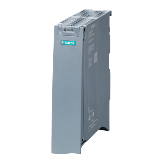
Product overview Properties Article number 6ES7155-5MU00-0CN0 View of the module Figure 3-1 View of the IM 155-5 MF HF interface module Interface module IM 155-5 MF HF (6ES7155-5MU00-0CN0) Equipment Manual, 11/2023, A5E53268530-AA... - Page 19 • Pulling and plugging I/O modules on the active backplane bus (multi hot swapping) • You can find additional information in the Active backplane bus (https://support.industry.siemens.com/cs/ww/en/view/109769815) Equipment Manual. The module supports the following functions (Page 22). Maximum configuration I/O data •...
- Page 20 Product overview 3.1 Properties Maximum configuration U connector setup • A maximum of one power supply module (PS) upstream from the interface module and two downstream from the interface module is possible. • If you use a power supply module (PS) upstream from the interface module, the maximum possible configuration is a total of 32 modules (up to 30 modules downstream from the interface module).
- Page 21 • 24 V DC connector (one included in the scope of delivery) Information on the BusAdapters is available in the BusAdapter (https://support.industry.siemens.com/cs/ww/en/view/109751716) Equipment Manual. For more information on accessories, refer to the Automation system S7-1500, ET 200MP System Manual (https://support.industry.siemens.com/cs/ww/en/view/59191792).
-
Page 22: Compatibility And Limitations
Product overview 3.2 Compatibility and limitations Compatibility and limitations Compatibility with the IM 155-5 MF HF interface module If you exchange or replace an interface module, the following table shows the compatibilities: • Between the interface modules IM 155-5 MF HF and IM 155-5 PN HF •... -
Page 23: Functions
Product overview 3.3 Functions Workaround for topological configuration If you receive the "Cable length mismatch" diagnostics, perform the following workaround: 1. Accept the diagnostics. If you cannot accept the diagnostics, continue with step 2. 2. Deselect the diagnostics in your Engineering System. Alternatively, perform step 3. 3. - Page 24 GSD file Portal) as of (TIA Portal) ule as of ule as of (https://support.i V19 with as of V19 ndus- try.siemens.com/ cs/ww/en/view/6 8189683) /third- party software Real-time communica- V5.0 tion Isochronous real-time V5.0 communication (IRT) Device replacement V5.0...
- Page 25 BusAdapter BA 2xM12 V5.0 Replacement part scenario The usability of the PROFINET IO functions depends on the configuration software (Siemens and/or third-party). Below, the usability of the PROFINET IO functions is described for STEP 7 only. Real-time communication A transmission method for PROFINET IO based on cyclic data exchange with a provider- consumer model.
- Page 26 You can find additional information on configuration of synchronized PROFINET devices in sync domains in the STEP 7 online help and • As of STEP 7 V12 (TIA Portal), in the PROFINET with STEP 7 (http://support.automation.siemens.com/WW/view/en/49948856) function manual • As of STEP 7 V5.5, in the PROFINET System Description (http://support.automation.siemens.com/WW/view/en/19292127) manual...
- Page 27 You can find additional information in the STEP 7 online help and • As of STEP 7 V12 (TIA Portal), in the PROFINET with STEP 7 (http://support.automation.siemens.com/WW/view/en/49948856) function manual • As of STEP 7 V5.5, in the PROFINET System Description (http://support.automation.siemens.com/WW/view/en/19292127) manual...
- Page 28 You can find additional information in the STEP 7 online help and • As of STEP 7 V12 (TIA Portal), in the PROFINET with STEP 7 (http://support.automation.siemens.com/WW/view/en/49948856) function manual • As of STEP 7 V5.5, in the PROFINET System Description (http://support.automation.siemens.com/WW/view/en/19292127) manual...
-
Page 29: System Redundancy On V5.0 X
You can find more information on this topic in the STEP 7 online help and • As of STEP 7 V12 (TIA Portal), in the PROFINET with STEP 7 (http://support.automation.siemens.com/WW/view/en/49948856) function manual • As of STEP 7 V5.5, in the PROFINET System Description (http://support.automation.siemens.com/WW/view/en/19292127) system manual... -
Page 30: Configuration Control (Option Handling)
Reference You can find more information • In chapter Configuration control (option handling) (Page 35) • On the Internet (http://support.automation.siemens.com/WW/view/en/29430270) • In the STEP 7 online help. Interface module IM 155-5 MF HF (6ES7155-5MU00-0CN0) Equipment Manual, 11/2023, A5E53268530-AA... -
Page 31: System Redundancy On S7-400H
• The connection setting (transmission medium/duplex) must be set to "Full duplex". You can find examples for system redundancy in the Fault-tolerant systems S7-400H (http://support.automation.siemens.com/WW/view/en/60458386) manual. Combination of system redundancy and Shared Device The IM 155-5 MF HF interface module can be connected to up to four IO controllers but only to one H-CPU pair. -
Page 32: Wiring
You can find additional information on connecting the interface module and on accessories (selectable BusAdapters) in the system manual S7-1500, ET 200MP Automation system (https://support.industry.siemens.com/cs/ww/en/view/59191792). Further information on connecting the BusAdapters can be found in the BusAdapter (https://support.industry.siemens.com/cs/us/en/view/109751716) Equipment Manual. Interface module IM 155-5 MF HF (6ES7155-5MU00-0CN0) Equipment Manual, 11/2023, A5E53268530-AA... -
Page 33: Block Diagram
Wiring 4.2 Block diagram Block diagram Schematic circuit diagram ① Switch 24 V DC supply voltage ② ET 200MP backplane bus interface Ground and electronics ③ Backplane bus LK 1,2 Link TX/RX LED (green) ④ Internal power supply MT 1,2 MAINTENANCE FiberOptic LED (SCRJ port, yellow) Supply voltage infeed... -
Page 34: Parameter
Parameter Parameters Table 5- 1 Parameters for IM 155-5 MF HF interface module Parameters Value range Default setting Efficiency range Connection to supply voltage L+ Connection/No con- Connection ET 200MP nection Configuration control Disable/enable Disable ET 200MP Description of parameters 5.2.1 Connection to supply voltage L+ Parameter "Connection to supply voltage L+"... -
Page 35: Configuration Control (Option Handling)
Reference See the section on the power budget and the forming of power segments in the system manual S7-1500, ET 200MP Automation system (https://support.industry.siemens.com/cs/ww/en/view/59191792). Requirement In order to generate diagnostics, the IM 155-5 MF HF interface module parameters must have been assigned once. -
Page 36: Configuration Control (Option Handling)
Parameter 5.3 Configuration control (option handling) Configuration control (option handling) 5.3.1 Configuration control and control data record Operating principle You can use the configuration control to operate different real configurations (options) with a single configuration of the ET 200MP distributed I/O system. This is made possible by a configurable assignment of configured station modules to actually existing ones. - Page 37 Parameter 5.3 Configuration control (option handling) Rules: Arrangement of the modules The following table shows the slot number assignment: Table 5- 2 Assignment of slot numbers Slot Modules Note Power supply module (optional) Before the interface module Interface module Interface module (slot 1) is not an ele- ment of the configuration control, but rather controls this 2 - 31...
- Page 38 (Page 17) and the section on the power budget in the system manual S7-1500, ET 200MP Automation system (https://support.industry.siemens.com/cs/ww/en/view/59191792). Particularly for a power supply (PS) module on slot 0, we recommend that you avoid reconfiguration.
- Page 39 Parameter 5.3 Configuration control (option handling) Combination of configuration control and Shared Device The configuration control function in a Shared Device is therefore only for the modules of the IO controller that has subscribed to the interface module. Modules that are assigned to another IO controller or not assigned at all cannot be specified as real slots (Shared Device on module level).
-
Page 40: Feedback Data Record
Parameter 5.3 Configuration control (option handling) 5.3.2 Feedback data record Feedback data record The feedback data record provides information on the accuracy of the module assignment and gives you the chance to detect assignment errors in the control data record. The feedback data record is mapped by a separate data record 197. -
Page 41: Configure Configuration Control Without Empty Slots
Parameter 5.3 Configuration control (option handling) Error messages The following error messages are returned if an error occurs during reading of the feedback data record: Table 5- 7 Error messages Error code Meaning 80B1 Invalid length 80B5 Configuration control not configured 80B8 Parameter error 5.3.3... - Page 42 Parameter 5.3 Configuration control (option handling) Data record of the example The following table shows the structure of the control data record for the above example. Table 5- 8 Data record for example "Configure configuration control without empty slots" Byte Element Code Explanation...
-
Page 43: Extending The Configuration
Parameter 5.3 Configuration control (option handling) 5.3.4 Extending the configuration Operating principle You can add modules at the end of the configuration with this procedure. The configured configuration can also be extended from the center based on freely selectable slot assignment. - Page 44 Parameter 5.3 Configuration control (option handling) Data record of the example The following table shows the structure of the control data record for the above example. Table 5- 9 Data record for example "Extending the configuration" Byte Element Code Explanation Block length Header Block ID...
-
Page 45: Combining Configurations
Parameter 5.3 Configuration control (option handling) 5.3.5 Combining configurations Operating principle You can combine the different procedures with configuration control. Figure 5-3 Combining configurations Interface module IM 155-5 MF HF (6ES7155-5MU00-0CN0) Equipment Manual, 11/2023, A5E53268530-AA... - Page 46 Parameter 5.3 Configuration control (option handling) Data record of the example The following table shows the structure of the control data record for the above example. Table 5- 10 Data record for example "Combining configurations" Byte Element Code configura- Code configura- Explanation tion 1 tion 2...
-
Page 47: Interrupts And Diagnostic, Error, And System Alarms
Interrupts and diagnostic, error, and system alarms Status and error displays Introduction Diagnostics by means of LED display is an initial tool for error localization. To narrow down the error, you usually evaluate the display of the CPU, the display of the module status in STEP 7 or the diagnostics buffer of the CPU. - Page 48 Interrupts and diagnostic, error, and system alarms 6.1 Status and error displays LED display The figure below shows the LED display on the IM 155-5 MF HF interface module. ① RUN (green) ② ERROR (red) ③ MAINT (yellow) Figure 6-1 LED display on the interface module Interface module IM 155-5 MF HF (6ES7155-5MU00-0CN0) Equipment Manual, 11/2023, A5E53268530-AA...
- Page 49 Interrupts and diagnostic, error, and system alarms 6.1 Status and error displays Meaning of the LEDs RUN/ ERROR/ MAINT Table 6- 1 Meaning of the LEDs RUN/ ERROR/ MAINT LEDs Meaning Remedy ERROR MAINT Supply voltage not present or too low at Check the supply voltage or turn it on at the interface module interface module.
-
Page 50: Interrupts
S7-1500 CPU, to the S7-1500 CPU web server, to the HMI device and in STEP 7. For additional information on the system diagnostics, refer to the System diagnostics function manual (http://support.automation.siemens.com/WW/view/en/59192926). 6.2.1 Triggering of a diagnostic interrupt Triggering of a diagnostic interrupt For an incoming or outgoing event (e.g., wire break on a channel of an I/O module), the... -
Page 51: Triggering Of A Hardware Interrupt
Interrupts and diagnostic, error, and system alarms 6.2 Interrupts 6.2.2 Triggering of a hardware interrupt Triggering of a hardware interrupt When a hardware interrupt occurs, the CPU interrupts execution of the user program and processes the hardware interrupt OB. The event that triggered the interrupt is entered in the start information of the hardware interrupt OB. -
Page 52: Alarms
You can find the structure of the diagnostic data records and programming examples in the programming manual From PROFIBUS DP to PROFINET IO (http://support.automation.siemens.com/WW/view/en/19289930) and in the application example on the Internet (http://support.automation.siemens.com/WW/view/en/24000238). Interface module IM 155-5 MF HF (6ES7155-5MU00-0CN0) -
Page 53: Maintenance Events
6.3 Alarms Causes of error and corrective measures The error causes and corrective measures of the diagnostic alarms are described in the manuals for the I/O modules (http://support.automation.siemens.com/WW/view/en/67296522/133300) in the Interrupts/Diagnostic alarms section. See also Channel diagnostics (Page 54) 6.3.2... - Page 54 Interrupts and diagnostic, error, and system alarms 6.3 Alarms The interface module signals a maintenance event to the higher-level diagnostic system in the case of the following events: Table 6- 3 Triggering of a maintenance event Maintenance alarm Event Meaning Remedy Maintenance de- Synchronization loss •...
-
Page 55: Channel Diagnostics
Interrupts and diagnostic, error, and system alarms 6.3 Alarms 6.3.3 Channel diagnostics Function Channel diagnostics provides information about channel faults in modules. Channel faults are mapped as channel diagnostics in IO diagnostic data records. The "RDREC" instruction is used to read the data record. Structure of the diagnostic data records •... - Page 56 • Verify if the firmware update file you are using comes from a secure source. • Download the firmware again from the Siemens Support Web page. • Repeat the firmware update. Structure of the manufacturer-specific diagnostic data records (firmware version lower than V4.2)
- Page 57 Interrupts and diagnostic, error, and system alarms 6.3 Alarms Structure USI = W#16#0001 Table 6- 7 Structure of USI = W#16#0001 Data block name Contents Note Bytes W#16#0001 Manufacturer-specific diagnostics in case of overload in an ET 200MP power segment Followed by 3 reserved bytes Reserved Reserved...
- Page 58 Interrupts and diagnostic, error, and system alarms 6.3 Alarms USI structure = W#16#0004 Table 6- 10 USI structure = W#16#0004 Data block name Contents Note Bytes W#16#0004 Manufacturer-specific diagnostics if no U connector is detected on an IM port Followed by 4 reserved bytes Reserved Reserved Reserved...
-
Page 59: Invalid Configuration States Of The Et 200Mp On Profinet Io
Additional information You can find additional information on maximum configuration, power budget and power segments in the system manual S7-1500, ET 200MP Automation system (https://support.industry.siemens.com/cs/ww/en/view/59191792). See also: Status and error displays (Page 46) Interface module IM 155-5 MF HF (6ES7155-5MU00-0CN0) -
Page 60: Stop Of The Io Controller And Recovery Of The Io Device
Interrupts and diagnostic, error, and system alarms 6.3 Alarms 6.3.5 STOP of the IO controller and recovery of the IO device STOP of the SIMATIC IO controller Diagnostics received from the IO device while the IO controller is in STOP state do not initiate a call of the corresponding OBs when the IO controller starts up. -
Page 61: Strain Relief
Strain relief Product overview Article number 6ES7590-5DA00-0AA0 (VPE: 5 strain relief units incl. screws) View Figure 7-1 Strain relief Properties • The strain relief is a mechanical protective device for the electrical Industrial Ethernet/PROFINET cables on the BusAdapter • The strain relief is suitable for all electrical Industrial Ethernet/PROFINET cables of the BusAdapter •... -
Page 62: Installing
Strain relief 7.2 Installing Installing Requirement • The Industrial Ethernet/PROFINET cables are not inserted on the BusAdapter. The inserted Industrial Ethernet/PROFINET cables hamper the mounting of the strain relief. • Mount the strain relief before connecting the BusAdapter. Tools required Screwdriver TX10 (torx). - Page 63 Strain relief 7.2 Installing 4. Screw the BusAdapter to the PROFINET device (1 screw with 0.25 Nm tightening torque). 5. Fasten each Industrial Ethernet/PROFINET cable individually to the strain relief with the cable ties. Figure 7-3 Strain relief installed Interface module IM 155-5 MF HF (6ES7155-5MU00-0CN0) Equipment Manual, 11/2023, A5E53268530-AA...
-
Page 64: Technical Specifications
Technical specifications Technical specifications of the IM 155-5 MF HF The following table shows the technical specifications as of 11/2023. You will find a data sheet including daily updated technical specifications on the Internet (https://support.industry.siemens.com/cs/de/de/pv/6ES7155-5AA00-0AC0/td?dl=en). Article number 6ES7155-5MU00-0CN0 General information... -
Page 65: Busadapter Ba 2Xrj45 V5.0 X
Technical specifications Article number 6ES7155-5MU00-0CN0 Input current Current consumption (rated value) 0.16 A; at 24 V DC and without load Current consumption, max. 1.2 A Inrush current, max. 13 A I²t 0.1 A²·s Power Infeed power to the backplane bus 16 W Power available from the backplane bus 3.4 W;... - Page 66 Technical specifications Article number 6ES7155-5MU00-0CN0 PROFINET IO Device Services – Yes; 250 µs to 4 ms in 125 µs frame – PROFIenergy – Prioritized startup – Shared device – Number of IO Controllers with shared de- vice, max. Interface types RJ 45 (Ethernet) PROFINET with 100 Mbit/s full duplex (100BASE- •...
- Page 67 Technical specifications Article number 6ES7155-5MU00-0CN0 Interrupts/diagnostics/status information Status indicator Alarms Diagnostics function Diagnostics indication LED Yes; green LED • RUN LED Yes; red LED • ERROR LED Yes; Yellow LED • MAINT LED Yes; 2x green LEDs on BusAdapter • Connection display LINK TX/RX Potential separation between backplane bus and electronics...
-
Page 68: Dimension Drawing
Dimension drawing The dimension drawing of the module on the mounting rail, as well as a dimension drawing with open front panel, are provided in the appendix. Always observe the specified dimensions for installation in cabinets, control rooms, etc. Dimension drawings of the IM 155-5 MF HF interface module Figure A-1 Dimension drawing of the IM 155-5 MF HF interface module, front and side views Interface module IM 155-5 MF HF (6ES7155-5MU00-0CN0) -
Page 69: Dimension Drawing
Dimension drawing A.1 Dimension drawing Dimension drawing of the IM 155-5 MF HF interface module, side view with open front cover Figure A-2 Dimension drawing of the IM 155-5 MF HF interface module, side view with open front flap Dimension drawing The figure below shows the dimension drawing of the strain relief. -
Page 70: Response Times
Response times Response times of the ET 200MP Introduction The response time of the IM 155-5 MF HF is made up of: • The update time configured for the IM as IO device. plus • The backplane bus cycle time. Note Validity of the formula The following formula does not apply to Shared Device mode. - Page 71 Response times B.1 Response times of the ET 200MP Example configuration for the calculation of the backplane bus cycle time The following are used in the example: Table B- 1 Example configuration for the calculation of the backplane bus cycle time I/O module Output data Input data...
- Page 72 μs + (500 μs x 1 + 500 μs) = 510 μs + 1000 μs = 1510 μs Reference Additional information about performance measurements is available on the Internet (http://support.automation.siemens.com/WW/view/en/34677186/136000&cspltfrm=0&cssw= 0&csbinh=5). Interface module IM 155-5 MF HF (6ES7155-5MU00-0CN0) Equipment Manual, 11/2023, A5E53268530-AA...
Need help?
Do you have a question about the SIMATIC ET 200MP and is the answer not in the manual?
Questions and answers