Table of Contents
Advertisement
Quick Links
OWNER'S MANUAL
SD-E4HDU
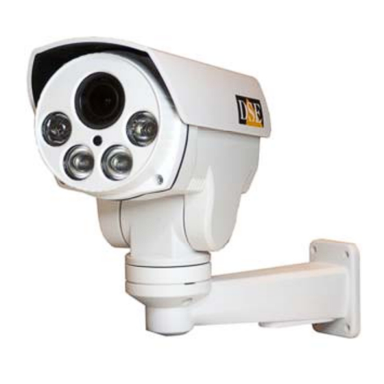
Product description
The camera you have purchased is a very innovative product. Yes
It is a camera
Similar in concept to a fixed camera, but capable of being panned in all directions and equipped
with zoom, also remotely controllable.
Connections and Mounting
Bracket Mounting - The first thing to
Bracket Mounting - The first thing to
fasten the bracket supplied separately to the camera body with the two screws provided (1). The
cables pass through the bracket and protruding rear.
It mounts generally in the output cables so as not to leave exposed wires
The cameras are to be fixed to the wall and are not suitable for ceiling mounting. Fix the wall
bracket with the bolts (3)
Connections
The camera
DSE srl - Digital Surveillance Equipment - WWW.DSE.EU
Document: SD-E4HDU 1M5
Document: SD-E4HDU 1M5
Document: SD-E4HDU 1M5
SD-E4HDU mini PTZ camera AHD
The camera is equipped with different connectors: a female BNC for the video, a DC power outlet
and two cables (ORANGE / YELLOW) for remote control (RS485).
BNC video output - At the BNC female bayonet connecting the video cable that leads then
BNC video output - At the BNC female bayonet connecting the video cable that leads then
to monitor or DVR typically using RG59 coaxial cable and BNC connector. You can also use
twisted pair cables with balun converters.
Jack DC12V - At the power plug must connect a 12VDC power supply stabilized by at least
Jack DC12V - At the power plug must connect a 12VDC power supply stabilized by at least
2,000 mA, such as RE-AL5 model (not included).
The requested plug is the standard 5.5 mm. Attention to use STABILIZED feeders that provide
12V in any load condition. The use of a different supply voltage from 12VDC can generate video
disorders and in the worst cases damage the camera. Beware extension power cables are too
long or
small section,
excessive fall
IR illuminator ignition.
Telemetry. It is of the serial connection that leads the movement commands to the camera.
Telemetry. It is of the serial connection that leads the movement commands to the camera.
The SD series cameras use an RS485 serial line (RS485 BUS) which is formed with a pair of
twisted wires.
ORANGE: RS485 A
ORANGE: RS485 A
YELLOW: RS485B
YELLOW: RS485B
E 'essential that the two cables are wound between them and non-parallel. In principle the RS485
serial line can extend up to 1200 meters in length and along it are connected in cascade devices.
The section of the cables closely depends on the length of the connection: for medium distances
is sufficient a section of 0.5 mm, while if it is necessary to reach considerable distances (max.
1200 m.) Should be used upper sections of 1 mm or even 2.5 mm.
In carrying out the wiring
recommended, but not necessary to use shielded cable. The network CAT5 cable containing four
twisted pairs is great for the realization of a RS485 BUS. A serial BUS part of rule from a control
member which can be a SD-CON3D console or a DVR. The cameras must be connected in
cascade ie entering and exiting from the clamps 2 and RS485A RS485B. It 'important not to
confuse the two cables (AB) during the connection of the equipment.
The order in which the devices are connected to the BUS has no relevance. Each device will be
identified by its own unique address that will properly address the instructions.
connected to the same BUS up to 256 cameras. The console, do not require any addressing,
while for the cameras is necessary to set a different address for each camera, as described
below.
Page: 1
Page: 1
that could
to introduce
species voltage at the time
It's possible
Advertisement
Table of Contents

Related Manuals for DSE SD-E4HDU


Summary of Contents for DSE SD-E4HDU
-
Page 1: Product Description
BUS up to 256 cameras. The console, do not require any addressing, while for the cameras is necessary to set a different address for each camera, as described below. Connections DSE srl - Digital Surveillance Equipment - WWW.DSE.EU... - Page 2 In an RS485 bus it is important that all the cameras and all the command organs share the same communication speed and that each camera has different address. The camera default setting is as follows: DSE srl - Digital Surveillance Equipment - WWW.DSE.EU...
- Page 3 Here you can set the dwell time of each preset during the tour (10 seconds Factory) N = 1..255 seconds CALL 52 CALL Start tour CALL 98 With this preset you start the tour DSE srl - Digital Surveillance Equipment - WWW.DSE.EU...
- Page 4 With this preset you access the OSD setup menu of the camera. Not all control devices, however, allow you to move in this menu, we recommend that you use the RE-UTC2 remote control to make changes. Main technical data www.dseitalia.it/dati_speed-dome.htm DSE srl - Digital Surveillance Equipment - WWW.DSE.EU...
Need help?
Do you have a question about the SD-E4HDU and is the answer not in the manual?
Questions and answers