Table of Contents
Advertisement
Quick Links
NXP Semiconductors
User's Guide
FRDM-KL28Z User's Guide
1. Introduction
The Freedom development platform is a set of software
and hardware tools for evaluation and development. It is
an ideal tool for the rapid prototyping of
microcontroller-based applications.
The FRDM-KL28Z supports power supply voltage
range from 1.71 V to 3.6 V. It features a KL28Z, a
device boasting a maximum operating frequency of 96
MHz, up to 512 KB Flash and numerous analog and
digital peripherals.
The FRDM-KL28Z includes the NXP open standard
embedded serial and debug adapter known as
OpenSDA. This circuit offers the user several options
for serial communications, flash programming and run-
control debugging.
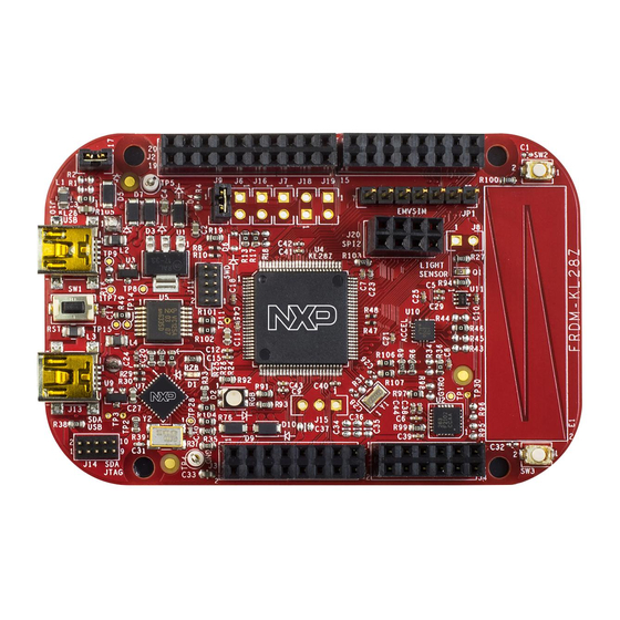
The FRDM-KL28Z hardware is form-factor compatible
with the Arduino™ R3 pin layout, providing a broad
range of expansion board options. The on-board
interfaces include an RGB LED, a 6-axis digital sensor
(combining a 3D accelerometer and 3D magnetometer),
a 3-axis digital angular rate gyroscope, an ambient light
sensor, and a capacitive touch slider.
There are many software development tool options
available to the user. Choices include Kinetis Design
Studio (KDS), IAR Embedded Workbench, Keil MDK
featuring the µVision IDE, and so on.
All of these features combine to give users the freedom
needed to rapidly prototype many embedded designs: a
© 2016 NXP B.V.
Document Number: FRDMKL28ZUG
Contents
1.
Introduction .................................................................... 1
2.
Getting Started ................................................................ 2
3.
FRDM-KL28Z Features .................................................. 2
4.
FRDM-KL28Z Hardware Description .............................. 4
4.1.
Power supply ........................................................ 4
4.2.
Serial and debug adapter (OpenSDA) .................... 5
4.3.
Microcontroller ..................................................... 7
4.4.
Capacitive touch slider .......................................... 9
4.5.
I2C Inertial Sensor .............................................. 10
4.6.
RGB LED........................................................... 11
4.7.
Visible light sensor ............................................. 11
4.8.
EMVSIM Header ................................................ 12
4.9.
SPI2 Header ....................................................... 13
4.10.
Analog reference voltage..................................... 13
4.11.
Input/output headers............................................ 14
5.
References .................................................................... 15
6.
Revision History ........................................................... 15
Rev. 0 , 06/2016
Advertisement
Table of Contents

Subscribe to Our Youtube Channel
Related Manuals for NXP Semiconductors FRDM-KL28Z


Summary of Contents for NXP Semiconductors FRDM-KL28Z
-
Page 1: Table Of Contents
Visible light sensor ..........11 digital peripherals. 4.8. EMVSIM Header ..........12 4.9. SPI2 Header ............13 The FRDM-KL28Z includes the NXP open standard 4.10. Analog reference voltage........13 4.11. Input/output headers..........14 embedded serial and debug adapter known as References .............. -
Page 2: Getting Started
2. Getting Started Refer to the FRDM-KL28Z Quick Start Package for step-by-step instructions for getting started with the freedom board. See the “Jump Start Your Design” section at nxp.com/FREDEVPLA for the Quick Start Package and software lab guides. - Page 3 RGB LED KL28Z Accelerometer and Magnetometer Digital Angular SPI2 Header Rate Gyroscope Capacitive touch slider Ambient Light Sensor NMI button LLWU button Figure 1. FRDM-KL28Z feature call-outs Figure 2. FRDM-KL28Z block diagram FRDM-KL28Z User’s Guide, Rev. 0, 06/2016 NXP Semiconductors...
-
Page 4: Frdm-Kl28Z Hardware Description
4. FRDM-KL28Z Hardware Description 4.1. Power supply The FRDM-KL28Z offers a design with multiple power supply options. It can be powered from the USB connector, battery on the board, the VIN pin on the I/O header, or an off-board 1.71-3.6 V supply from the 3.3 V pin on the I/O header. -
Page 5: Serial And Debug Adapter (Opensda)
Regulated 3.3 V supply. Sources power to the P3V3 supply rail through an optional back P3V3_VREG drive protection Schottky diode. P3V3 Main supply rail for the FRDM-KL28Z. Can be sourced from P3V3_VREG (J3 pin 8). KL28Z MCU power supply. Header J17 provides a convenient means for KL28Z energy P3V3_KL28Z consumption measurements. - Page 6 KL28Z.Several of the default OpenSDA applications provided by Freescale, including the MSD Flash programmer and the P&E debug application, providing a USB communications device class (CDC) interface that bridges serial communications between the USB host and this serial interface. FRDM-KL28Z User’s Guide, Rev. 0, 06/2016 NXP Semiconductors...
-
Page 7: Microcontroller
FRDM-KL28Z Hardware Description 4.3. Microcontroller The FRDM-KL28Z is a MCU module featuring the MKL28Z512VLL7, a Kinetis microcontroller with USB 2.0 full-speed OTG controller in a 100 LQFP package. An on-board debug circuit, OpenSDA, provides a SWD interface and a power supply input through a mini-USB connector, as well as serial to USB and CDC class compliant UART interface. - Page 8 The Kinetis KL28 microcontroller features a dual-role USB controller with on-chip full-speed and low- speed transceivers. The USB interface on the FRDM-KL28Z is configured as a full-speed USB device. J10 is the USB connector for this interface. As shown in Figure 6.
-
Page 9: Capacitive Touch Slider
The sole debug interface on all Kinetis L series devices is a Serial Wire Debug (SWD) port. The primary controller of this interface on the FRDM-KL28Z is the onboard OpenSDA circuit. However, a 2x5-pin Cortex Debug connector, J11, provides access to the SWD signals for the KL28Z MCU. The following table shows SWD connector signals description for KL28Z. -
Page 10: I2C Inertial Sensor
I2C bus and two GPIO signals as shown in the following table and Figure 9. By default, the I2C address is 0x20 (As SA0 pulled low). Table 6. Gyroscope FXAS21002CQ signal connections FXAS21002CQ KL28Z PTE24 PTE25 INT1 PTE0 INT2 PTE1 FRDM-KL28Z User’s Guide, Rev. 0, 06/2016 NXP Semiconductors... -
Page 11: Rgb Led
Green Cathode PTC4 Blue Cathode PTE31 4.7. Visible light sensor An ambient light sensor is connected to PTD5, which is shown in Figure This sensor may be isolated from PTE22 by removing J8. FRDM-KL28Z User’s Guide, Rev. 0, 06/2016 NXP Semiconductors... -
Page 12: Emvsim Header
CPU/platform clock (as shown in Figure 12). The following table shows the user-accessible signals available on EMVSIM. These signals are actually connected to the external pins by JP1. Figure 12. Visible light EMVSIM Header FRDM-KL28Z User’s Guide, Rev. 0, 06/2016 NXP Semiconductors... -
Page 13: Spi2 Header
The onboard ADC of the FRDM KL28Z uses the Reference Voltage High (VREFH) and Reference Voltage Low (VREFL) pins to set high and low voltage references for the analog modules. By default VREFH is attached to P3V3_KL28Z (3.3 V Supply). VREFL is connected to GND. FRDM-KL28Z User’s Guide, Rev. 0, 06/2016 NXP Semiconductors... -
Page 14: Input/Output Headers
P5-9V_VIN-16 PTC11-15 14-PTC12 PTC10-13 12-PTB11 PTB0-2 1-PTE20 PTC7-11 PTB1-4 3-PTE21 PTC9-9 10-PTB10 PTC3-6 5-PTE22 PTC8-7 8-PTB9 PTB3-8 7-PTE23 6-PTB2 PTC0-5 PTC2-10 9-PTC5 4-PTB17 PTB19-3 PTC1-12 11-PTE30 PTB18-1 2-PTB16 Figure 15. Input/output headers FRDM-KL28Z User’s Guide, Rev. 0, 06/2016 NXP Semiconductors... -
Page 15: References
Revision History 5. References The reference documents for the FRDM-KL28Z hardware are shown below. All documents can be found at nxp.com • FRDM-KL28Z Quick Start Guide • FRDM-KL28Z User’s Guide • FRDM-KL28Z Schematics PDF • OpenSDA User’s Guide (document OPENSDAUG) •... - Page 16 How to Reach Us: Information in this document is provided solely to enable system and software Home Page: implementers to use NXP products. There are no express or implied copyright licenses nxp.com granted hereunder to design or fabricate any integrated circuits based on the information in this document.
Need help?
Do you have a question about the FRDM-KL28Z and is the answer not in the manual?
Questions and answers