
Related Manuals for Rockwell Automation Allen-Bradley 1768-ENBT


Summarization of Contents
Important User Information
Safety and Hazard Information
Critical safety warnings, hazard alerts (explosion, injury, shock, burn, arc flash), and important usage notes.
Preface
Download Add-on Profiles and Firmware
Information on obtaining necessary software profiles and firmware updates.
Additional Resources
List of other publications and resources for further information.
Chapter 1 Install a 1756 EtherNet/IP Communication Module
Installation Summary
Overview of installing the 1756 EtherNet/IP communication module.
Environment and Enclosure Considerations
Safety and environmental considerations for module installation.
North American Hazardous Location Approval
Safety guidelines for hazardous locations in North America.
European Hazardous Location Approval
Safety guidelines for hazardous locations in Europe (Ex marking).
Prevent Electrostatic Discharge
Precautions to prevent damage from electrostatic discharge.
Grounding Considerations
Guidelines for proper grounding of the module.
Set Network IP Address
Steps to configure the network IP address for the module.
Determine Module Slot Location
Guidance on selecting the appropriate slot for the module in the chassis.
Install the Module
Step-by-step instructions for physically installing the module.
Connect the Module
Information on wiring the module to the network.
Connect via RJ45
Details for connecting via RJ45 Ethernet cable.
Connect via Fiber Optic
Details for connecting via fiber optic cable.
Connect via USB Port
How to connect the module using its USB port.
Apply Power and Check Status
Steps to power up the chassis and verify module status.
Module Under Power Installation/Removal
Procedure for installing or removing the module while power is applied.
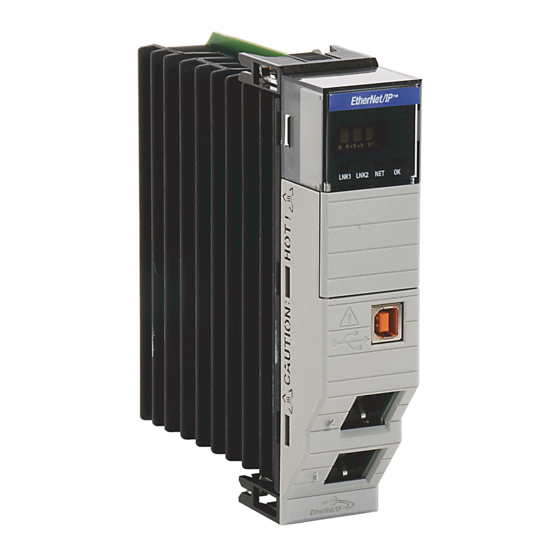
Chapter 2 Install a 1768 EtherNet/IP Communication Module
Environment and Enclosure Considerations
Safety and environmental considerations for module installation.
North American Hazardous Location Approval
Safety guidelines for hazardous locations in North America.
European Hazardous Location Approval
Safety guidelines for hazardous locations in Europe (Ex marking).
Prevent Electrostatic Discharge
Precautions to prevent damage from electrostatic discharge.
Installation Summary
Overview of installing the 1768 EtherNet/IP communication module.
Grounding Considerations
Guidelines for proper grounding of the module.
Set Network IP Address
Steps to configure the network IP address for the module.
Install the Module
Step-by-step instructions for physically installing the module.
Mount Module with Screws
Instructions for mounting the module using screws.
Mount on DIN Rail
Instructions for mounting the module on a DIN rail.
Wire the Module
Information on wiring the module to the network.
Connect via RJ45
Details for connecting via RJ45 Ethernet cable.
Apply Power and Check Status
Steps to power up the chassis and verify module status.
Remove the Module
Procedure for removing the module from the system.
Chapter 3 Install a 1769 EtherNet/IP Adapter
Environment and Enclosure Considerations
Safety and environmental considerations for adapter installation.
North American Hazardous Location Approval
Safety guidelines for hazardous locations in North America.
System Configuration
Rules and guidelines for planning adapter system configuration.
Example Configurations
Illustrations of valid system setups for the adapter.
Installation Summary
Overview of installing the 1769 EtherNet/IP adapter.
Grounding Considerations
Guidelines for proper grounding of the adapter.
Set Network IP Address
Steps to configure the network IP address for the adapter.
Install Adapter in 1769 System
Instructions for installing the adapter into a 1769 system.
Adapter Description
Description of the adapter's components and features.
System Assembly
Steps for assembling the Compact I/O system with the adapter.
Mount Adapter and I/O Modules
Procedures for mounting the adapter and I/O modules.
Minimum Spacing
Recommendations for spacing around the adapter for ventilation.
Mount Adapter with Screws
Instructions for mounting the adapter using screws.
Mount to Module with Screws (Template)
Method for drilling mounting holes using modules as a template.
Mount on DIN Rail
Instructions for mounting the adapter on a DIN rail.
Wire the Adapter
Information on wiring the adapter to the network.
Remove or Replace Adapter
Procedures for removing or replacing the adapter.
Chapter 4 Set the Network IP Address
Set IP Address with BOOTP/DHCP Server
Steps to set the IP address using BOOTP/DHCP.
Set IP Address with RSLinx or Studio 5000
Setting IP address using RSLinx or Studio 5000.
Set IP Address with Rotary Switches
Configuring IP address via rotary switches on the module.
Use DHCP Software
Using DHCP software for network configuration.
Reset IP Address to Factory Default
Procedure to reset the module's IP address to factory defaults.
Chapter 5 Configure a Workstation for EtherNet/IP
Select Ethernet Driver
Choosing the appropriate Ethernet driver for the workstation.
Configure Ethernet Communication Driver
Steps to configure the Ethernet driver in RSLinx software.
Chapter 6 USB Communication
Set Up USB Hardware
Initial setup for USB hardware connection.
Configure Module via USB Port
Configuring modules using the module's USB port.
Load Firmware via USB Port
Process for loading firmware via the USB port.
Appendix A 1756 EtherNet/IP Status Indicators
Single-port Module Status Indicators
Details of status indicators for single-port 1756 modules.
Dual-port Module Status Indicators
Details of status indicators for dual-port 1756 modules.
Appendix B 1768 EtherNet/IP Module Status Indicators
1768 Module Status Indicators Table
Details of status indicators for 1768 EtherNet/IP modules.
Appendix C 1769 EtherNet/IP Adapter Status Indicators
1769 Module Status Indicators Table
Details of status indicators for 1769 EtherNet/IP adapters.
Appendix D Fiber Cable and LC Connector
Specifications
Specifications for fiber cable and LC connectors.
Rockwell Automation Support
Technical Support Center
Access to knowledgebase, FAQs, chat, and forums.
Local Technical Support Phone Numbers
Directory for finding local support phone numbers.
Direct Dial Codes
Codes to route calls directly to technical support engineers.
Literature Library
Access to installation instructions, manuals, and brochures.
Product Compatibility and Download Center (PCDC)
Information on product interaction, features, and firmware.
Documentation Feedback
Method for providing feedback to improve documentation.
Need help?
Do you have a question about the Allen-Bradley 1768-ENBT and is the answer not in the manual?
Questions and answers