Advertisement
Table of Contents
- 1 Step 1: Remove Power from the Controller.
- 2 Step 3: Assemble the 1769-SM2 Module to the Controller.
- 3 Step 4: Mount the 1769-SM2 Module.
- 4 Step 5: Replacing the Module Within a System.
- 5 Step 6: Connect the Module to the Drive(S).
- 6 Step 7: Ground the Module.
- 7 Step 8: Apply Power.
- Download this manual
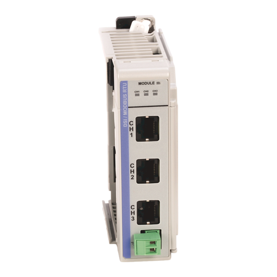
1769-SM2 Compact I/O DSI/Modbus
Network Communication Module
This document instructs how to install a 1769-SM2 Compact I/O DSI/Modbus
Network Communication Module into the controller.
ATTENTION: Risk of equipment damage exists. Remove power before
installing or removing the 1769-SM2 module. When you install or remove
!
the module with power applied, an electrical arc may occur. An electrical
arc can cause personal injury or equipment damage by:
• Sending an erroneous signal to your system's field devices, causing
unintended machine motion.
• Causing an explosion in a hazardous environment.
Electrical arcing causes excessive wear to contacts on both the module
and its mating connector. Worn contacts may create electrical resistance.
ATTENTION: Risk of equipment damage exists. The 1769-SM2
module contains ESD (Electrostatic Discharge) sensitive parts that can be
!
damaged if you do not follow ESD control procedures. Static control
precautions are required when handling the module. If you are unfamiliar
with static control procedures, refer to Guarding Against Electrostatic
Damage, publication 8000-4.5.2.
Related Documentation
Document
1769-SM2 Compact I/O DSI/Modbus
Network Communication Module User
Manual, publication 1769-UM013
Guarding Against Electrostatic Damage,
publication 8000-4.5.2
Wiring and Grounding Guidelines for PWM
AC Drives, publication DRIVES-IN001
Documentation can be obtained online at www.rockwellautomation.com/literature.
To order paper copies of technical documentation, contact your local Rockwell
Automation distributor or sales representative.
For information such as firmware updates and answers to drive-related questions, go
to the Drives Service & Support web site at
on the "Downloads" or "Knowledgebase" link.
Step 1
Remove power from the controller.
Installation Instructions
Description
Provides complete installation, wiring, setup, and
communication information for the 1769-SM2 Network
Communication Module.
Provides static control procedures for protecting
electrostatic discharge sensitive parts.
Guidelines for proper wiring, grounding, and shielding, and
standard practices for noise protection.
www.ab.com/support/abdrives
and click
Advertisement
Table of Contents

Related Manuals for Rockwell Automation Allen-Bradley 1769-SM2


Summary of Contents for Rockwell Automation Allen-Bradley 1769-SM2
- Page 1 Installation Instructions 1769-SM2 Compact I/O DSI/Modbus Network Communication Module This document instructs how to install a 1769-SM2 Compact I/O DSI/Modbus Network Communication Module into the controller. ATTENTION: Risk of equipment damage exists. Remove power before installing or removing the 1769-SM2 module. When you install or remove the module with power applied, an electrical arc may occur.
- Page 2 Step 2 Set the 1769-SM2 module Configuration Mode switch and Operating Mode (Single/Multi-Drive) switch to appropriate positions. For complete switch setting details, see the 1769-SM2 module User Manual. Step 3 Assemble the 1769-SM2 module to the controller. It can be attached to adjacent controller modules before or after mounting.
- Page 3 Step 4 Mount the 1769-SM2 module. ATTENTION: Risk of equipment damage exists. During panel or DIN rail mounting of all devices, be sure that all debris (metal chips, wire strands, etc.) is kept from falling into the 1769-SM2 module. Debris that falls into the module could cause damage on power up.
- Page 4 Figure 2 1769-SM2 Module with CompactLogix Controller 50 mm 35 mm 70 mm 35 mm Mounting Hole 28.5 mm (1.97 in) (1.38 in) (2.76 in) (1.38 in) Dimension (1.12 in) 40 mm 35 mm 35 mm 35 mm 35 mm (1.58 in) (1.38 in) (1.38 in)
- Page 5 e. Place the modules back on the panel, and check for proper hole alignment. f. Attach the modules to the panel using the mounting screws. B. DIN Rail Mounting — The 1769-SM2 module can be mounted using the following DIN rails: •...
- Page 6 F. Before installing the replacement 1769-SM2 module, be sure that the bus lever on the right-side adjacent module is in the unlocked (fully right) position. G. Slide the replacement 1769-SM2 module into the open slot. H. Connect the 1769-SM2 module and adjacent modules together by locking (fully left) the bus levers on the 1769-SM2 module and the right-side adjacent module.
- Page 7 Step 8 Apply power. ATTENTION: Risk of equipment damage, injury, or death exists. Unpredictable operation may occur if you fail to verify that parameter settings are compatible with your application. Verify that settings are compatible with your application before applying power to the drive. A.
- Page 8 Europe/Middle East/Africa: Rockwell Automation, Pegasus Park, De Kleetlaan 12a, 1831 Diegem, Belgium, Tel: (32) 2 663 0600, Fax: (32) 2 663 0640 Asia Pacific: Rockwell Automation, Level 14, Core F, Cyberport 3, 100 Cyberport Road, Hong Kong, Tel: (852) 2887 4788, Fax: (852) 2508 1846 Publication 1769-IN084A-EN-P –...
Need help?
Do you have a question about the Allen-Bradley 1769-SM2 and is the answer not in the manual?
Questions and answers