Table of Contents
Advertisement
Quick Links
© Panduit Corp. 2018
TO REDUCE RISK OF INJURY, THE USER
MUST READ THE USER MANUAL
NOTE: Throughout this document, the UPS00100DC (Uninterruptible Power Supply)
may also be referred to as "UPS".
Email:
techsupport@panduit.com
EU Website:
www.panduit.com/emea
IA-CD-0009 Rev. 07
UPS00100DC
UNINTERRUPTIBLE POWER SUPPLY (UPS)
USER MANUAL
English
7
Page 1 of 46
Part No: UPS00100DC
Technical Support:
Tel: 1-888-506-5400 ext. 83255
Panduit Europe • EMEA Service Center
Almelo, Netherlands
Tel: +31-546-580-452
Fax: +31-546-580-441
IA-CD-0009
Rev: 07 09-2018
Advertisement
Table of Contents

Related Manuals for Panduit UPS00100DC


Summary of Contents for Panduit UPS00100DC
- Page 1 USER MANUAL English Part No: UPS00100DC TO REDUCE RISK OF INJURY, THE USER MUST READ THE USER MANUAL NOTE: Throughout this document, the UPS00100DC (Uninterruptible Power Supply) may also be referred to as “UPS”. Technical Support: Email: Tel: 1-888-506-5400 ext. 83255 techsupport@panduit.com...
-
Page 2: Table Of Contents
USER MANUAL UPS00100DC © Panduit Corp. 2018 Table of Contents INTRODUCTION................................6 1.1. BACKGROUND ................................. 6 1.2. PURPOSE .................................. 7 1.3. EQUIPMENT OVERVIEW ............................7 1.4. OPTIONAL LOAD SENSE MODULE..........................7 1.5. CABLE DETAILS ................................. 7 1.6. TERMS AND ABBREVIATIONS ..........................8 UPS GENERAL SPECIFICATIONS............................ - Page 3 USER MANUAL UPS00100DC © Panduit Corp. 2018 4.6. DC POWER INPUT ..............................19 4.7. SENSE INPUT ................................19 4.8. DC POWER OUTLET..............................19 4.9. GROUND ................................20 4.10. CON-CONTROL RELAY ............................20 4.11. Status LEDs – Visual Indicators ..........................20 NETWORK INSTALLATION .............................
- Page 4 USER MANUAL UPS00100DC © Panduit Corp. 2018 5.6.11.4. SNMPv3 ................................ 35 5.6.11.5. SNMP TRAPS (NOTIFICATIONS) ........................36 5.7. NETWORK ................................37 5.8. CHARGE ................................. 39 5.8.1. CHARGE STATUS ............................39 5.8.2. CHARGE SPEED ............................. 39 5.8.3. CHARGE POWER ............................40 5.8.4.
- Page 5 Table 9: UPS Charge Status Indicators ..........................45 Table 10: UPS Status to SNMP Trap Mapping ........................46 NOTE: In the interest of higher quality and value, Panduit products are continually being improved and updated. Consequently, pictures may vary from the enclosed product.
-
Page 6: Introduction
USER MANUAL UPS00100DC © Panduit Corp. 2018 1. INTRODUCTION 1.1. BACKGROUND The Uninterruptible Power Supply (UPS) is designed to provide backup power to a 24 VDC load in the event of power dips or power outages. The unit utilizes Electrochemical Double-Layer Capacitor cells (EDLCs) as the energy storage device to provide a long, maintenance-free operating life without the need for battery replacement. -
Page 7: Purpose
Please see the Load Sense Module UPS003LSM instruction manual for integrating the load sense module to your system. Document number PA27224A01 is included with the LSM or on www.panduit.com. The schematic diagram for the system configuration with redundant power supplies and the LSM in Figure 7 shows the wiring Figure 2 shows the Load Sense Module. -
Page 8: Terms And Abbreviations
Web Browser Interface 2. UPS GENERAL SPECIFICATIONS 2.1. Model Part Number • UPS00100DC - Panduit's 100-Watt Uninterruptible Power Supply 2.2. Input Power • Voltage: 24.0 to 28.0 VDC Power Minimum: 24W with no load, charging on “slow charge” setting per Section 5.8.2 •... -
Page 9: Environmental
USER MANUAL UPS00100DC © Panduit Corp. 2018 2.4. Environmental • Operating Temperature: -40 to +60°C Operating Humidity: 0 to 95% RH, non-condensing • Operational Vibration: 2G at 10 to 500 Hz • • Operational Shock: 20G (11ms 3 bumps / direction, 18 bumps in total) Storage (non-operational) Temperature: -40 to +70°C... -
Page 10: Installation
USER MANUAL UPS00100DC © Panduit Corp. 2018 Model No. / Manufacture Date Input / Output / Temp. Ratings Conformances Warnings Approvals MAC Address Serial Number Figure 3: Product Label and Description NOTE: For use in Class I, Zone 2 environment, the UPS/LSM must be used in an enclosure certified for use in Class I, Zone 2, Groups IIC. -
Page 11: Performance
USER MANUAL UPS00100DC © Panduit Corp. 2018 • Alerting/Communication wiring is along the bottom edge of the UPS. o Control Output: Isolated, SPST-NO (Form A) contact, rated 30 VDC at 1A maximum that may be connected to an alarm. Contact will be closed when the output of the UPS is providing power. -
Page 12: Maintenance
Is trained to identify and install appropriately-sized Branch Circuit Disconnect(s) with appropriately-sized • Branch-Circuit Protective Rating and Short-Circuit Current Rating (SCCR) before connecting any Panduit product to the branch circuit. •... -
Page 13: Safety Warnings
Save all warnings and instructions for future reference. Table 1: Safety Warnings Panduit Corp. recommends the UPS be used with all installed safety features. Customer assumes all liability for injury that could result from improper use of this UPS and responsibility for all necessary training to ensure safe operation of this UPS. -
Page 14: Electrical Safety Practices
USER MANUAL UPS00100DC © Panduit Corp. 2018 3.2. Electrical Safety Practices GROUNDING: In the event of a malfunction or breakdown, grounding provides a path of least resistance for electric current which reduces the risk of electrical shock. Improper connection of the equipment grounding conductor can result in a risk of electric shock. -
Page 15: Service
4.2. PRODUCT INSPECTION/Registration Inspect the UPS for any visible signs of damage before installing. If damaged, please contact Panduit customer support at 1-800-777-3300 or cs@panduit.com. Please register your product to receive notification of firmware and product updates at: https://pages.panduit.com/Product-Registration-Request.html... -
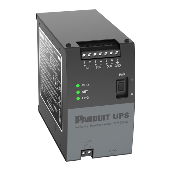
Page 16: Figure 4: Ups Front Panel Details
USER MANUAL UPS00100DC © Panduit Corp. 2018 Figure 4: UPS Front Panel Details Figure 5: Reset Button and Serial Number IA-CD-0009 Rev. 07 Page 16 of 46... -
Page 17: Hardware Install
USER MANUAL UPS00100DC © Panduit Corp. 2018 4.4. HARDWARE INSTALL Figure 6: DIN Rail Installation No minimum side-to-side spacing to other devices is required for proper operation of the UPS. However, ensure there is ample space to cable components to protect the cabling integrity. Also ensure there is access to the power switch, the LEDs, the reset button, and the Ethernet port on the underside of the device. -
Page 18: On/Off Power Switch
USER MANUAL UPS00100DC © Panduit Corp. 2018 Figure 7: System Wiring Diagram Warning: A disconnect switch is required on the input circuit in accordance with the National Electric Code, ANSI/NFPA 70. 4.5.1. ON/OFF POWER SWITCH This toggle switch enables operation of the UPS when it is set to the “ON” position. When set to the “OFF”... -
Page 19: Dc Power Input
The two terminals above the legend marked “SEN” are to be connected to the optional load sense module, Panduit part number UPS0030LSM. The input voltage should not be greater than 28 VDC. The terminals are designed to accept 18 to 12 AWG (0.823 mm to 3.31 mm... -
Page 20: Ground
USER MANUAL UPS00100DC © Panduit Corp. 2018 The terminals are designed to accept 18 to 12 AWG (0.823 mm to 3.31 mm ) wire. Torque terminal screws to 7 in-lbs. (0.7909 Nm). Insure the proper local and national regulations are followed when selecting wiring components with regards to the system configuration. -
Page 21: Network Installation
USER MANUAL UPS00100DC © Panduit Corp. 2018 5. NETWORK INSTALLATION 5.1. ETHERNET The Ethernet port marked below the legend <…> is a standard RJ-45 type jack shown in Figure 5: Reset Button and Serial Number. This port should be connected to a router running a DHCP server. By Factory Default, the UPS obtains an IP address from the DHCP server. -
Page 22: Module
Restore Factory Defaults (See RESTORE FACTORY DEFAULTS Section 6.3 or RESTORE Section 5.6.9) unless specified in the table below. If normal operation does not resume after Restore Factory Defaults, contact Panduit for technical support or service. Table 3: Module Status... -
Page 23: Input, Volts And Input, Amps
USER MANUAL UPS00100DC © Panduit Corp. 2018 If the device is in an environment that is above the operating WARNING: temperature, the Module Status in the WBI will be set to this status. The Over corresponding MOD LED indicator shall be flashing red. -
Page 24: Events
This is typically a hardware fault condition. The UPS will continue to provide pass- through power, but the UPS backup power will be permanently disabled. Contact Panduit Customer support for the next steps to be taken. -
Page 25: Figure 10: Even Log Web Page
USER MANUAL UPS00100DC © Panduit Corp. 2018 The Event Log stores a maximum of 1,000 sequential events. Oldest events are deleted when the Event Log reaches maximum capacity. The below screen capture illustrates some examples of the event log entries that the user may see. -
Page 26: Username And Password
A Username and Password is required to access the Network, Charge, and Setting pages on the UPS. The default Username is “Panduit UPS” and the default password is the device serial number. The device serial number may be obtained from the label on the side of the UPS (refer to Figure 5: Reset Button and Serial Number). -
Page 27: Settings
5.6.1. MODEL The Model displays the Model Number of this UPS device. The UPS00100DC is the model number of the 100 Watt UPS that has been received with this User Manual. This Model number is not changeable by the user. -
Page 28: Serial Number
USER MANUAL UPS00100DC © Panduit Corp. 2018 The below confirmation window will pop-up when this “RESET” button is clicked. Click the “RESET” button to continue or click the “CANCEL” button to cancel the reset. Figure 13: Reset Pop-up Window 5.6.3. -
Page 29: Username
5.6.5. USERNAME The Username displays the Username assigned to the unit. The factory default Username is “Panduit UPS” (case sensitive). The Username may be changed by the user. Clicking on the “CHANGE” button allows the user to change the default Username. A pop-up window (shown below) queries the user to enter a new Username. -
Page 30: Firmware Version
Click the “^” in the “Save” button and select “Save As”. Select the location on the PC that the file should be saved in and note the location for later use. Exit out of the Panduit Download window. -
Page 31: Language
USER MANUAL UPS00100DC © Panduit Corp. 2018 this document for the default settings. Click the “RESTORE” button to restore the UPS to factory defaults. Click the “CANCEL” button the cancel the operation and keep the current settings. After a Restore to Factory Defaults, the user should perform a RESET. -
Page 32: Snmp
USER MANUAL UPS00100DC © Panduit Corp. 2018 Figure 18: Settings Web Page 5.6.11. SNMP By factory default, the SNMP agent is disabled. To enable the SNMP agent, click the EDIT button next to the version of SNMP you want to support. Clicking on the SNMP “EDIT” button will pop-up a window to enable the SNMP agent. -
Page 33: Ip (Snmp Agent) Port
USER MANUAL UPS00100DC © Panduit Corp. 2018 Figure 19: SNMP Configuration Web Page 5.6.11.1. IP (SNMP AGENT) PORT Clicking on the IP Port “EDIT” button will pop-up a window to change the IP Port (referred to as the SNMP Agent port) from the default value of 162. -
Page 34: Syscontact Or Syslocation
USER MANUAL UPS00100DC © Panduit Corp. 2018 Figure 21: SNMP Configuration Web Page (With IP Port Changed) 5.6.11.2. SYSCONTACT or SYSLOCATION The sysLocation and sysContact values are used by network managers to indicate where the device is located and who is responsible for managing it. Clicking on the System “EDIT” button will pop-up a window to change the System Contact and System Location from the default values of SNMP sysContact and SNMP sysLocation. -
Page 35: Snmpv1 And Snmpv2C
USER MANUAL UPS00100DC © Panduit Corp. 2018 Figure 22: SNMP System Pop-up Window 5.6.11.3. SNMPv1 and SNMPv2C Clicking on the SNMP v1/v2C “EDIT” button will pop-up a window to add and remove community names with permissions. Enter a Community Name then set the read/write/trap access appropriately. If more than one user is needed, click the “ADD”... -
Page 36: Snmp Traps (Notifications)
USER MANUAL UPS00100DC © Panduit Corp. 2018 Figure 24: SNMPv3 Edit Pop-up Window 5.6.11.5. SNMP TRAPS (NOTIFICATIONS) SNMP Notifications are often referred to as SNMP Traps. Clicking on the Notification “EDIT” button will pop-up a window to add and remove IP Addresses that have been identified to receive the traps. The... -
Page 37: Network
The network tab allows the Device Name and Network settings to be changed. The Device Name displays the Device Name assigned to the unit. The factory default Device Name is “Panduit UPS”. The Device Name may be changed by the user. Clicking on the Device name “CHANGE” button allows the user to change the default Device Name. -
Page 38: Figure 28: Network Settings Change Web Page
USER MANUAL UPS00100DC © Panduit Corp. 2018 NOTE: It is recommended that only a qualified person with a network background make changes to these network settings. When set to DHCP the UPS will sent out a request to get an IP Address from the DHCP server on the Ethernet network. -
Page 39: Charge
USER MANUAL UPS00100DC © Panduit Corp. 2018 5.8. CHARGE Figure 29: Change Web Page 5.8.1. CHARGE STATUS The Charge Status indicates the state of the internal energy storage of the UPS, closely follows the front panel CHG indicator. The following table shows the charge status based on UPS input and output conditions. -
Page 40: Charge Power
USER MANUAL UPS00100DC © Panduit Corp. 2018 Figure 30: Charge Speed Change Pop-up Window 5.8.3. CHARGE POWER “Charge Power, W” displays the charge power in Watts used by the UPS when it is charging. NOTE: Charge Power is only updated during charge mode. -
Page 41: Operation
USER MANUAL UPS00100DC © Panduit Corp. 2018 6. OPERATION 6.1. LOAD SUPPORT The UPS is designed to draw a maximum input current of 156 Watts (100W plus 56 Watts additional for fast charge). The power supply connected to the UPS must support the load as well as the charging power for the energy storage elements. -
Page 42: General Operation
USER MANUAL UPS00100DC © Panduit Corp. 2018 6.4. GENERAL OPERATION Once the UPS is installed per Sections 4 and 5 , power may be applied to the Primary Power Supply and the Secondary Power Supply if present. The UPS can then be switched to the “ON” position. If the input voltage is too high, the UPS will fault and the MOD LED flashes red. - Page 43 USER MANUAL UPS00100DC © Panduit Corp. 2018 Select the “Support” pulldown Hover over “Download Center” and select “Industrial Uninterruptible Power Supply (UPS Downloads” Scroll down on the Web page to “EtherNet/IP* and FactoryTalk** Network Support Files” Section Each EDS file has a specific location on the web.
-
Page 44: Troubleshooting
UPS00100DC © Panduit Corp. 2018 USER MANUAL 7. TROUBLESHOOTING 7.1. LED STATUS INDICATORS 7.1.1. MOD LED – Module Status Indicator NOTE: The WBI (Section 5.4.1) will contain detailed error messages. The WBI should be the first step in troubleshooting the UPS. -
Page 45: Net Led - Network Status Indicator
© Panduit Corp. 2018 USER MANUAL UPS00100DC 7.1.2. NET LED – Network Status Indicator Table 8: UPS Network Status Indicators Indicator State Summary Requirement Steady Off No Power, No IP The device is powered off or is powered on but with... -
Page 46: Snmp Traps
UPS00100DC © Panduit Corp. 2018 USER MANUAL 7.2 SNMP Traps Below is a high-level table of the alarms that can be added or removed from the UPS SNMP Alarm table. Anytime an alarm is added or removed from the UPS SNMP Alarm table an add or remove SNMP Trap will be sent.
Need help?
Do you have a question about the UPS00100DC and is the answer not in the manual?
Questions and answers