
Related Manuals for Panasonic CJ-HDR216A


Summary of Contents for Panasonic CJ-HDR216A
- Page 1 HD Analog Recorder Quick Start Guide CJ-HDR216A Model No. CJ-HDR416A Version 1.0.0...
-
Page 2: Table Of Contents
Hardware Installation and Connection ..................1 Check Unpacked DVR ....................1 About the Panels and Cover ................... 1 After Remove the Chassis....................1 HDD Installation....................... 1 1.4.1 CJ-HDR216A ......................1 1.4.2 CJ-HDR416A ......................2 Rack Installation (CJ-HDR416A only) ................3 Front Panel ........................3 1.6.1 CJ-HDR216A ...................... - Page 3 2.4.1 Record Operation ....................24 2.4.2 Snapshot Operation ..................24 Search & Playback ......................25 2.5.1 Smart Search ....................30 2.5.2 Accurate Playback by Time ................31 2.5.3 Bookmark Playback ..................31 Schedule ........................33 2.6.1 Quick Setup ...................... 35 2.6.2 Redundancy ......................
- Page 4 Welcome Thank you for purchasing our HD Analog Recorder (DVR)! This quick start guide will help you become familiar with our DVR in a very short time. Before installation and operation please read the following safeguards and warnings carefully!
- Page 5 Important Safeguards and Warnings 1.Electrical safety All installation and operation here should conform to your local electrical safety codes. The product must be grounded to reduce the risk of electric shock. Please use three-pin power socket (with GND). An apparatus with CLASS I construction shall be connected to a MAINS socket outlet with a protective earthing connection.
-
Page 6: Hardware Installation And Connection
Please check the data cable, power cable, COM cable and main board cable connection is secure or not. 1.4 HDD Installation Please use HDD of 7200rpm or higher. 1.4.1 CJ-HDR216A This DVR has two SATA HDDs. ① Loosen the screws of the ②... -
Page 7: Cj-Hdr416A
④ ⑤ ⑥ Turn the device upside down Fix the HDD firmly. Connect the HDD cable and and then turn the screws in firmly. power cable. ⑦ ⑧ Put the cover in accordance Secure the screws in the rear with the clip and then place the panel. -
Page 8: Rack Installation (Cj-Hdr416A Only)
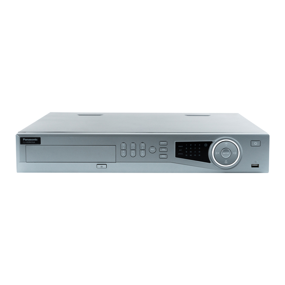
If there are more accessories connected in the rack, please take precaution measures in case the rack power is overload. 1.6 Front Panel 1.6.1 CJ-HDR216A The front panel is shown as below. See Figure 1-1. Figure 1-1 Please refer to the following sheet for front panel button information. -
Page 9: Cj-Hdr416A
Name Icon Function Go to previous menu, or cancel current operation (Close the top interface or controls). Cancel When playback, click it to restore real-time monitor mode. Confirm current operation. Confirm ENTER Go to default button. ... - Page 10 Name Icon Function Switch current activated controls, move up and down. Left/2 When device is in 1-channel playback mode, use it to control Right/3 playback control bar process. Play/Pause/6 When playback, click it to pause, click it again to play again. Reverse/Pause/5 When playback, click it to begin reverse play.
-
Page 11: Rear Panel
1.7 Rear Panel Rear panel of CJ-HDR216A is shown as below. See Figure 1-3. Figure 1-3 Please refer to the following sheet for detailed information. Icon Name Note Power switch Power on/off button. VGA video VGA video output port. Output analog video signal. Can output port connect to the monitor to view analog video output. - Page 12 The rear panel of CJ-HDR416A is shown as below. See Figure 1-4. Figure 1-4 Please refer to the following sheet for detailed information. Icon Name Note Power switch Power on/off button. It is for general COM debug to configure IP RS-232 RS-232 debug COM.
- Page 13 Icon Name Note Controller 12V power output. It is to control CTRL 12V Control power output the on-off alarm relay output. Connect to video output devices such as VIDEO OUT Video output port Audio output port. It is to output the analog audio signal to the devices such as the AUDIO OUT Audio output port...
-
Page 14: Connection Sample
1.8 Connection Sample CJ-HDR216A The connection sample is shown as below. See Figure 1-5. Figure 1-5 CJ-HDR416A The connection sample is shown as below. See Figure 1-6. Figure 1-6... -
Page 15: Alarm Input And Output Connection
1.9 Alarm Input and Output Connection Important Please refer to the specifications for the alarm input and output channel amount. Do not merely count the alarm input and out channel amount according to the ports on the rear panel. 1.9.1 Alarm Input and Output Details Figure 1-7 Alarm input port 1~16. -
Page 16: Alarm Output Port
Please parallel connect the Ground of the DVR and the ground of the alarm detector. Please connect the NC port of the alarm sensor to the DVR alarm input (ALARM). Use the same ground with that of DVR if you use external power to the alarm device. Figure 1-8 1.9.3 Alarm Output Port ... - Page 17 Between coil and contacts 1000VAC 1min Dielectric strength Between open contacts 400VAC 1min ≤5ms Operate time (at nomi. volt.) ≤5ms Release time (at nomi. volt.) Bounce time (at nomi. volt.) Approx. 5ms ≤65K Temperature rise (at nomi. volt.) Shock resistance 98m/s 10Hz –...
-
Page 18: Overview Of Navigation And Controls
2 Overview of Navigation and Controls Please note the following contents are based on our CJ-HDR416A product. For detailed operation instruction of other series products, please refer to the User’s Manual included in the resource CD. Before operation, please make sure: ... -
Page 19: Auto Resume After Power Failure
2.1.3 Auto Resume after Power Failure The system can automatically backup video and resume previous working status after power failure. 2.1.4 Replace Button Battery Please make sure to use the same battery model if possible. We recommend replace battery regularly (such as one-year) to guarantee system time accuracy. - Page 20 contain at least two categories. Usually we recommend the strong password. Prompt Question: If you set the prompt question here. On the login interface, hover over device can display the corresponding prompt question for you to remind the password. WARNING STRONG PASSWORD RECOMMENDED-For your device own safety, please create a strong password of your own choosing.
-
Page 21: Reset Password
Figure 2-3 Set security questions. Note After setting the security questions here, you can answer the security questions to reset admin password. Refer to chapter 2.2.2 Reset Password for detailed information. Cancel the security questions box and then click Save button to skip this step. Set security questions and corresponding answers. - Page 22 Figure 2-4 Figure 2-5 CAUTION Continuous five times login failure will result in account lock! Please reboot the device or wait for 5 minutes to try again if your account has been locked. 2. Click to reset login password by security questions (local menu only). See Figure 2-6.
- Page 23 Figure 2-6 3. Click Next button. Device displays Reset Password interface. See Figure 2-7. Figure 2-7 4. Input new password and then confirm. WARNING STRONG PASSWORD RECOMMENDED-For your device own safety, please create a strong password of your own choosing. The password shall be at least 8-digit containing at least two...
-
Page 24: Startup Wizard
types of the following categories: letters, numbers and symbols. We also recommend you change your password periodically especially in the high security system. 5. Click Save button to complete the reset setup. 2.2.3 Startup Wizard Tips Check the Startup checkbox in Figure 2-8, system goes to startup wizard again when it boots up the next time. - Page 25 Figure 2-10 Click Next button, you can go to SCHEDULE interface. See Figure 2-11. Figure 2-11 Click Next button, you can go to RECORD interface. See Figure 2-12.
- Page 26 Figure 2-12 Click Next button, you can go to NETWORK interface. See Figure 2-13. Figure 2-13 Click Finished button, system pops up a dialogue box. Click the OK button, the startup wizard is complete. See Figure 2-14.
-
Page 27: Preview
Figure 2-14 2.3 Preview After you logged in, the system is in live viewing mode. You can see system date, time, channel name and window number. If you want to change system date and time, you can refer to general settings (MAIN MENU -> SETTING -> SYSTEM -> GENERAL -> Date&Time). If you want to modify the channel name, please refer to the display settings (MAIN MENU ->... - Page 28 Figure 2-15 You can refer to the following sheet for detailed information. Name Function It is to playback the previous 5 - 60 minutes record of current channel. Please go to MAIN MENU -> SETTING -> SYSTEM -> Realtime Play GENERAL ->...
-
Page 29: Manual Record
2.4 Manual Record Note You need to have proper rights to implement the following operations. Please make sure the HDD has been properly installed. There are three ways for you to go to manual record menu. Right click mouse and then select Manual -> Record. ... -
Page 30: Search & Playback
Figure 2-17 Tips You can check All button after the corresponding status to enable/disable all-channel snapshot function. 2.5 Search & Playback Click PLAYBACK button in the main menu, or right click mouse and then select Playback when you are previewing, search interface is shown as below. See Figure 2-18. Usually there are three file types: ... - Page 31 Figure 2-18 Please refer to the following sheet for more information. Name Function Here is to display the playback picture or file. Display window Support 1/4/9/16-window playback. Playback mode: 1/4/9/16. In 1-window playback mode: you can select 1-16 channels. ...
- Page 32 Here you can select to playback the picture or the recorded file. You can select to play from the read-write HDD, from peripheral device or from redundancy HDD. Before you select to play from the peripheral device, please connect the corresponding peripheral device.
- Page 33 In playback mode, click it to play the next or the previous section. You can click continuously when you are watching the files from the same channel. │/│ In normal play mode, when you pause current play, you can click │ and │ to begin frame by frame playback. In frame by frame playback mode, click ►...
- Page 34 Select the file(s) you want to backup from the file list. You can check from the list. Then click the backup button, now you can see the backup menu. System supports customized path setup. After select or create new folder, click the Start button to begin the backup operation. The record file(s) will be saved in the specified folder.
-
Page 35: Smart Search
During the file playback process, you can switch to other channel via Manually the dropdown list or rolling the mouse. switch channel This function is null if there is no record file or system is in smart search when playback process. -
Page 36: Accurate Playback By Time
2.5.2 Accurate Playback by Time Select records from one day, click the list, you can go to the file list interface. You can input time at the top right corner to playback records by time. See image on the left side of the Figure 2-20. For example, input time 14:44.00 and then click Search button , you can view all the record files after 14:44.00 (The records includes current time). - Page 37 Playback Mark During 1-window playback mode, click mark file list button in Figure 2-18, you can go to mark file list interface. Double click one mark file, you can begin playback from the mark time. Play before Mark Time Here you can set to begin playback from previous N seconds of the mark time.
-
Page 38: Schedule
System resumes playback after you exit mark management interface. If the mark file you want to playback has been removed, system begin to playback from the first file in the list. 2.6 Schedule Note You need to have proper rights to implement the following operations. Please make sure the HDDs have been properly installed. - Page 39 Set record type. See Figure 2-24. Figure 2-24 Please draw manually to set record period. There are six periods in one day. See Figure 2-25. Figure 2-25 Please highlight icon to select the corresponding function. After completing all the setups please click save button, system goes back to the previous menu.
-
Page 40: Quick Setup
Figure 2-26 Figure 2-27 2.6.1 Quick Setup Copy function allows you to copy one channel setup to another. After setting in channel 1, click Copy button, you can go to interface Figure 2-28. You can see current channel name is grey such as channel 1. -
Page 41: Redundancy
Click the OK button to save current copy setup. Click the OK button in the Schedule interface, the copy function succeeded. Figure 2-28 2.6.2 Redundancy Redundancy function allows you to memorize record file in several disks. When there is file damage occurred in one disk, there is a spare one in the other disk. - Page 42 input snapshot mode as timing, size, quality and frequency. See Figure 2-30. In main menu, from SETTING -> STORAGE -> SCHEDULE -> Snapshot interface, please enable snapshot function. See Figure 2-31. Please refer to the following figure for detailed information. Figure 2-29 Figure 2-30...
-
Page 43: Trigger Snapshot
Figure 2-31 2.7.2 Trigger Snapshot Please follow the steps listed below to enable the activation snapshot function. After you enabled this function, system can snapshot when the corresponding alarm occurred. In main menu, from SETTING -> CAMERA -> ENCODE -> Snapshot interface, here you can input snapshot mode as trigger, size, image quality and frequency. - Page 44 Figure 2-32 Figure 2-33...
-
Page 45: Priority
Figure 2-34 2.7.3 Priority Please note the activation snapshot has the higher priority than schedule snapshot. If you have enabled these two types at the same time, system can activate the activation snapshot when alarm occurs, and otherwise system just operates the schedule snapshot. 2.7.4 Image FTP In the main menu, from SETTING ->... -
Page 46: Network
Please input the corresponding information here, if you just upload the image FTP. Figure 2-35 2.8 Network The interface is shown as in Figure 2-36. IP Version: There are two options: IPv4 and IPv6. Right now, system supports these two IP address format and you can access via them. -
Page 47: Pan/Tilt/Zoom
In this way, you can reduce packets and enhance network transmission efficiency. The following MTU value is for reference only. 1500: Ethernet information packet max value and it is also the default value. It is the typical setup when there is no VPN. It is the default setup of some router, switch or the network adapter. -
Page 48: Pan/Tilt/Zoom Operation
HD-CVI. Address: Input corresponding PTZ address. Baud Rate: Select baud rate. Data Bit: Select data bit. Stop Bit: Select stop bit. Check: There are five choices: None/Odd/Even/Mark/Space. Figure 2-37 After completing all the setups please click Save button, system goes back to the previous menu. - Page 49 Speed: value ranges from 1 to 8. Zoom. Focus. Iris. Click icon to adjust zoom, focus and iris. Figure 2-39 In Figure 2-39, please click direction arrows (See Figure 2-40) to adjust PTZ position. There are total 8 direction arrows.
-
Page 50: Web Operation
3 Web Operation Slightly difference may be found in the interface due to different series. 3.1 Network Connection Before web client operation, please check the following items: Step 1 Network connection is right. Step 2 DVR and PC network setup is right. Step 3 Use order ping ***.***.***.*** (* is DVR IP address) to check connection is OK or not. - Page 51 New Password/Confirm Password: The password ranges from 8 to 32 digitals. It can contain letters, numbers and special characters (excluding “'”, “"”, “;”, “:”, “&”) . The password shall contain at least two categories. Usually we recommend the strong password.
-
Page 52: Login
3.3 Login Step 1 Open IE and input DVR address in the address column. System pops up warning information to ask you whether install control or not. See Figure 3-4. Figure 3-4 Step 2 Please click Install button, system can auto run the installation. Or follow the prompts to save the installation package and install. -
Page 53: Main Window
3.4 Main Window 3.4.1 LAN Login For the LAN mode, after you logged in, you can see the main window. See Figure 3-6. Click the channel name on the left side; you can view the real-time video. Figure 3-6 3.4.2 WAN Login In WAN mode, after you logged in, the interface is shown as below. - Page 54 For detailed operation information, please refer to the User’s Manual included in the resource CD. Note For detailed operation introduction, please refer to our resource CD included in your package for electronic version of the User’s Manual. All pictured model is CJ-HDR416A, unless otherwise stated. ...
Need help?
Do you have a question about the CJ-HDR216A and is the answer not in the manual?
Questions and answers