
Subscribe to Our Youtube Channel
Related Manuals for Campbell HS2


Summary of Contents for Campbell HS2
- Page 1 HS2 and HS2P (HydroSense II) Revision: 3/14 C o p y r i g h t © 2 0 1 1 - 2 0 1 4 C a m p b e l l S c i e n t i f i c ,...
- Page 3 Campbell pricelist or product manual. Products not manufactured, but that are re-sold by Campbell, are warranted only to the limits extended by the original manufacturer. Batteries, fine-wire thermocouples, desiccant, and other consumables have no warranty.
- Page 4 SCIENTIFIC, INC., phone (435) 227-9000. After an application engineer determines the nature of the problem, an RMA number will be issued. Please write this number clearly on the outside of the shipping container. Campbell Scientific’s shipping address is: CAMPBELL SCIENTIFIC, INC.
-
Page 5: Table Of Contents
Table of Contents PDF viewers: These page numbers refer to the printed version of this document. Use the PDF reader bookmarks tab for links to specific sections. 1. Introduction ..............1 2. Cautionary Statements ..........2 3. Quickstart ..............2 4. - Page 6 A.20 Serial Number .................. A-8 Figures 1-1. HS2 HydroSense II System ..............1 1-2. HS2P HydroSense II Pole System ............1 4-1. HS2 Parts in Hard Carrying Case ............5 4-2. HS2P Carrying Tote ................6 4-3. HS2P Parts ................... 6...
- Page 7 Table of Contents Tables 4-1. Comparison of HydroSense II and HydroSense(I) ....... 3 4-2. HydroSense II Parts ................5 6-1. Default Soil Profiles ................10 7-1. Status Icons ..................16...
- Page 8 Table of Contents...
-
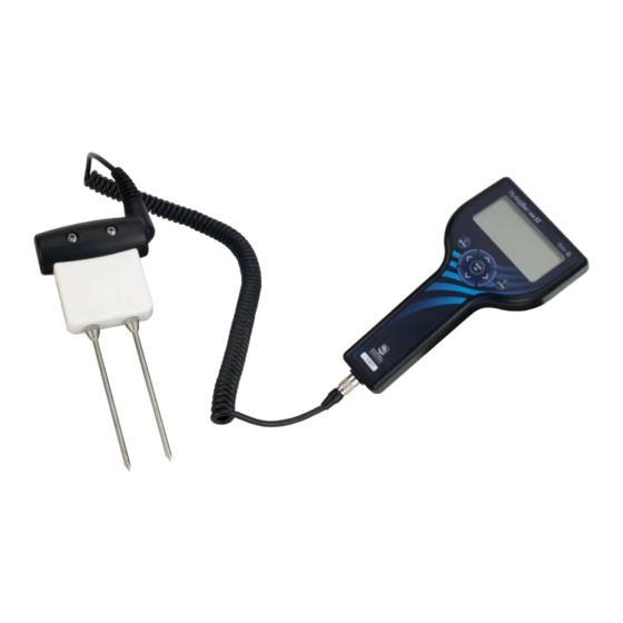
Page 9: Introduction
HS2 and HS2P Introduction FIGURE 1-1. HS2 HydroSense II System FIGURE 1-2. HS2P HydroSense II Pole System... -
Page 10: Cautionary Statements
2. Remove the blue protective strip from the display window. NOTE Steps 3 and 4 are for the HS2 only because the HS2P comes fully assembled. If using an HS2P, go directly to step 5. 3. Remove the HS2 sensor from the carry case. -
Page 11: Overview
HS2 and HS2P 5. Turn on the HydroSense II by holding the button for 3 seconds. 6. Establishing a GPS sync may take up to one minute or more. When the GPS icon is displayed ( ), synchronization has been successful. - Page 12 HS2 and HS2P Sensor rod length 20 cm and 12 cm 20 cm and 12 cm (NOT interchangeable) (interchangeable) Accuracy 20 cm rods: ±3% ±3% VWC (EC ≤ 4 dS/m) (EC < 2 dS/m) 12 cm rods: ±3% (EC≤ 6.5 dS/m)
-
Page 13: Hs2 Parts In Hard Carrying Case
Phillips screwdriver (pn 6290) Hard carrying case (pn 27789) Carrying tote (pn 29468) or hard carrying case (pn 27789) HydroSense II Support Software (HydroSoft) on CD Screwdriver CS658 Wrench Loctite HS2 Display Spare Battery Holder FIGURE 4-1. HS2 Parts in Hard Carrying Case... -
Page 14: Specifications
Spare Battery Holder Loctite FIGURE 4-3. HS2P Parts Below are spare and supporting parts available from Campbell Scientific: • Spare 20 cm rods (pn 26483) for the CS658 or CS658P sensor Spare 12 cm rods (pn 10184) for the CS659 or CS659P sensor •... -
Page 15: Current Drain
HS2 and HS2P Dimensions: 200 x 100 x 58 mm (7.9 x 3.9 x 2.3 in) Source: 4 x AA alkaline batteries Battery life: 6 to 12 months (depends on usage and battery quality) 5.1.1 Current Drain Asleep: 20 μA... -
Page 16: Height
HS2 and HS2P 5.3.1 Height Handle to bottom of sensor: 82.3 cm (32.4 in) Top of display to bottom of sensor: 96.5 cm (38 in) 5.3.2 Weight With display and sensor: 1.4 kg (3 lb) Without display: 1.1 kg (2.4 lb) -
Page 17: Water Deficit Data
HS2 and HS2P Water Deficit Data Water deficit data help irrigators with water management decisions. By default the HydroSense II does not show water deficit data on the display screen. To enable the water deficit data display, turn on Deficit Mode in the... -
Page 18: Configuring Soil Profiles
HS2 and HS2P These parameters are soil specific and grouped as “soil profiles”. The HydroSense II holds up to 10 soil profiles labeled “SOIL 1” through “SOIL 10”. Some soil profiles are preset to default values. These values may be used or overwritten as desired, but take care to record what soil type is used for each profile. - Page 19 HS2 and HS2P A soil profile page will be displayed. This page shows the reference values stored for this soil profile and the rod length used. To select this soil profile to apply to the current measurement, press highlight SELECT THIS SOIL and press New reference values can be set from the soil profile screen.
-
Page 20: Storage
EC. The calibration coefficients to convert measured time of travel to dielectric constant and water content are contained within the sensor head and are the intellectual property of Campbell Scientific. 6.4.4.2 Rod Insertion For accurate, repeatable measurements, the rods of the sensor must be fully inserted into the soil. -
Page 21: Soil Factors Affecting Measurement
HS2 and HS2P Soil is not homogeneous. Cracks, rocks, pore size, plant roots, and texture layers are not usually distributed uniformly throughout a measured profile. If the water content over a large area such as a cropped field is to be determined, several measurements may be required to establish a representative measurement. -
Page 22: Buttons
HS2 and HS2P Buttons User Interface Buttons Button Function Power/MENU — To turn the HydroSense II on or off, press and hold this button for 3 seconds. When pressed for less than 3 seconds in the main screen (p. 14), the main menu (p. -
Page 23: Gps Information
HS2 and HS2P 7.3.1 GPS Information The top bar of the screen displays the current date and time information. This time is synchronized with the GPS when available. The bottom bar shows the current GPS coordinates. Both values are updated automatically. -
Page 24: Measurement Display
HS2 and HS2P This change occurs automatically when the HydroSense II detects that it is within the boundaries of a zone. For more information on zones, please see Section 9.2, Geotagging and Zones (p. 19). The upper left of the main screen (p. -
Page 25: Deficit Display
HS2 and HS2P 7.3.4 Deficit Display When deficit mode is enabled, the water deficit section is displayed at center right of the main screen (p. 14). The following image shows the main screen without deficit mode enabled. The following image shows the main screen with deficit mode enabled. -
Page 26: What Is Stored
Software The HydroSense II ships with the latest version of the HydroSense II Support Software on CD. For the latest version, please contact Campbell Scientific. For a complete guide to the use of this software, please refer to the HydroSense II Support Software user guide. -
Page 27: Collecting Data
HS2 and HS2P The first time the HydroSense II unit is used with a new computer, the computer and HydroSense II must be “paired” before a connection can be made. The pairing code is “1234”. For more information, please refer to the HydroSense II Support Software user guide. - Page 28 HS2 and HS2P filtered and charted by the computer software based on the zone in which the data was collected. The HydroSense II keeps a table of up to 100 GPS zones in memory and searches through this table every few seconds to determine if it is within the boundary of a zone.
-
Page 29: Troubleshooting
HS2 and HS2P If the button is pressed when the GPS does not have a valid GPS sync, a warning message is display. This message warns that the current measurement may not be stored with an accurate date or time. To continue and store data without GPS information, press . -
Page 30: Maintenance
HS2 and HS2P On the display of my The forth icon is the Bluetooth connection icon. HydroSense II, the It appears only when the HydroSense II is paired battery icon, the to a computer and there is an active data Bluetooth icon, and the connection between them. -
Page 31: Removing Display From Hs2P Pole
HS2 and HS2P 7. Carefully replace the back cover of the display and replace the four screws. 8. Turn over the display and hold the button for 3 seconds to activate. 9. If using the HS2P, reinstall the display onto the pole. -
Page 32: Rod Replacement
Small bends can often be straightened by hand, but more serious bends may require rod replacement. Spare rods can be purchased from Campbell Scientific. • Spare 20 cm rods (pn 26483) for the CS658or CS658P sensor •... - Page 33 HS2 and HS2P The procedure for replacing the rods is as follows: 1. If using the HS2P, slip off the plastic bumper. Bumper Sensor Head Wrench 2. Use the wrench (pn 26156) to unscrew the rods. 3. Ensure that the threads of the replacement rods and the sensor body are clean and free from damage.
-
Page 34: Replacing An Hs2P Sensor
HS2 and HS2P 11.4 Replacing an HS2P Sensor HS2P Pole Sensor Bumper Hex Bolt 1. Unplug the cable that attaches the sensor to the display. 2. Remove the plastic bumper. 3. Use the wrench to remove the hex bolts and nuts that secure the sensor to the pole. - Page 35 HS2 and HS2P Begin an operating system upgrade with a fresh set of batteries. If the batteries in the HydroSense II fail during the update process, corruption of the operating system can result. Normally, the batteries can be replaced and the update...
- Page 36 HS2 and HS2P...
-
Page 37: Configuration Menus
Appendix A. Configuration Menus A.1 Main Menu To enter the main menu, press from the (p. 14). Using the main screen buttons, select the desired menu item and press . To exit the menu, press A.2 Deficit Mode This menu selects whether or not soil deficit is displayed. Select ON to show deficit results and OFF to hide them. -
Page 38: Time/Date Menu
Appendix A. Configuration Menus A.4 Time/Date Menu This submenu contains a list of settings to configure the clock system of the HydroSense II. Using the buttons, highlight one of the options and press . Alternatively, press to quit this menu. A.5 Time Set The HydroSense II clock is normally set automatically at GPS sync. -
Page 39: Time Zone
Appendix A. Configuration Menus A.7 Time Zone The HydroSense II is able to use its GPS to provide a very accurate clock. Whenever a valid GPS signal is detected, the clock is adjusted using the received time (in UTC) and the time zone selected in this menu. Time zones from UTC-12 to UTC+14 are available. -
Page 40: Time Synchronization
Appendix A. Configuration Menus A.8 Time Synchronization The HydroSense II uses its GPS to provide a very accurate clock. Whenever a valid GPS signal is detected, the clock is adjusted using the received time (in UTC) and the configured time zone. To use GPS synchronization, select ON from the list, or OFF to ignore the GPS time. -
Page 41: Brightness
Appendix A. Configuration Menus A.11 Brightness This menu allows the brightness of the LCD backlight to be adjusted. Since the backlight uses a significant amount of power, reducing the brightness will extend battery life. In bright, sunny conditions, the backlight has very little effect and generally doesn’t help readability, so the HydroSense II detects the ambient light conditions and automatically turns off the backlight when exposed to bright daylight. -
Page 42: Gps Settings
Appendix A. Configuration Menus A.14 GPS Settings This submenu contains a list of settings related to the GPS. Using the buttons, highlight one of the options shown and press to select that item. Alternatively, press to exit the menu. A.15 GPS Power This menu controls power to the GPS module. -
Page 43: System Settings
Appendix A. Configuration Menus A.17 System Settings This submenu contains a list of system-wide settings. Using the buttons, highlight one of the options shown and press . Alternatively, press to exit the menu. A.18 System on Time To save power, the HydroSense II will automatically power off after a period of inactivity. -
Page 44: Serial Number
Appendix A. Configuration Menus A.20 Serial Number This screen displays the serial number of the HydroSense II. This should match the serial number labeled on the front panel of the unit. Press exit this screen. - Page 46 Campbell Scientific Ltd. (CSL Germany) Fahrenheitstraße 13 28359 Bremen GERMANY www.campbellsci.de • info@campbellsci.de Campbell Scientific Spain, S. L. (CSL Spain) Avda. Pompeu Fabra 7-9, local 1 08024 Barcelona SPAIN www.campbellsci.es • info@campbellsci.es Please visit www.campbellsci.com to obtain contact information for your local US or international representative.
Need help?
Do you have a question about the HS2 and is the answer not in the manual?
Questions and answers