
Subscribe to Our Youtube Channel
Related Manuals for Flo Fab 1000/1004-IC11/2H Series


Summary of Contents for Flo Fab 1000/1004-IC11/2H Series
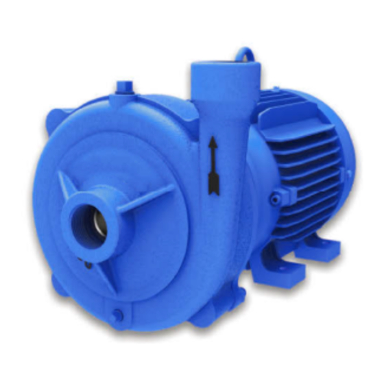
- Page 1 Installation, Operation & Maintenance Manual End Suction Centrifugal Pumps 1000/1004-IC1½H SERIES 1 - 15 HP @ 3500 RPM IMPORTANT! - Read all instructions in this manual before operating or servicing a pump.
-
Page 2: General Safety Information
( ammable, caustic, etc.) or use these pumps in Model Number: _____________________ IMPORTANT! - Flo Fab Pumps is not water over 160 °F. Do not exceed responsible for losses, injury or m a n u f a c t u r e r s r e c o m m e n d e d... - Page 3 ations & Dimensions SUCTION: 1½" NPT horizontal. DISCHARGE: 1½" NPT vertical. LIQUID TEMPERATURE: 160 °F (71 °C) max. VOLUTE: Cast iron ASTM A-48 class 30. INTERMEDIATE COUPLING: Cast iron ASTM A-48 class 30. IMPELLER: 5 vanes, closed, statically balanced. Cast iron ASTM A-48 class 30. SEAL: Mechanical, type 01.
- Page 4 Recommendations & Warnings Receiving inspection Service Stations Suction pipe hose reinforced Upon receiving the pump, it should To nd the nearest Barmesa Pumps authorized service shop, please su ciently robust prevent inspected damage collapsing by the di erence in shortages. If damage has occurred, directly contact your distributor or le a claim immediately with the the factory.
-
Page 5: Installation
Installation Figure 2 Wrong installation. A valve in the suction pipe is not recommended Air leaks pocket Long piping Concentric reducer Too much height "D" Piping elbow immediately installed after the suction Vortex Less than 4 "D" Without strainer Figure 3 Inclination. - Page 6 Installation & Operation Figure 6 Discharge piping. Correct Incorrect Expansive joint Safety shuto Service valve valve Expansive joint Swing check valve could cause a "water hammer" Retarded action Service valve check valve In order to determine the optimal 2. Check Pump Rotation - Improper 4.
-
Page 7: Operation And Maintenance
Operation & Maintenance Starting Mechanical Seal - To inspect or Step 1: Install the intermediate When starting for the rst time your coupling previously replace the shaft seal, remove the equipment check that the discharge removed. Make sure the shaft and body and impeller. -
Page 8: Maintenance
Maintenance Figure 7 Mechanical seal - Assembly. Intermediate Impeller coupling Shaft Impeller Seal lockwasher rotating member Shaft sleeve Hex. Lockwasher Spring screw Seal stationary Figure 8 Mechanical Seal - Sectional View. 1 - Ceramic seat 2 - Seal seat Buna-N 3 - Inox. - Page 9 Installation Table 1 Friction in meters x 100 m of piping. PIPING DIAMETER LITERS GALLONS 1" 1¼" 1½" 2" 2 ½" 3" 4" 5" 6" 8" 10" MINUTE MINUTE 4.54 6.86 1.77 9.62 2.48 16.2 1.53 20.6 5.22 2.42 25.1 6.34 2.94 38.7...
- Page 10 Installation Table 1 Equivalent length in meters of straight pipe and valve connections for calculating friction. DIAMETER PART DESCRIPTION 1" 1¼" 1½" 2" 2 ½" 3" 4" 5" 6" STANDARD 90° 0.84 1.07 1.22 1.68 1.98 2.44 3.35 4.12 4.88 ELBOW MEDIUM RADIUS 0.69 0.92 1.07 1.37 1.68 2.14 2.75 3.51 4.27...
-
Page 11: Troubleshooting Chart
- That the motor is suitable for the pump. NOTE: Flo Fab Pumps assumes no responsibility for damage or injury due to disassembly in the field. Disassembly of the pumps or supplied accessories other than at Flo Fab Pumps or its authorized service centers, automatically voids warranty.
Need help?
Do you have a question about the 1000/1004-IC11/2H Series and is the answer not in the manual?
Questions and answers