
Related Manuals for Flo Fab 1.25FFGP Series


Summary of Contents for Flo Fab 1.25FFGP Series
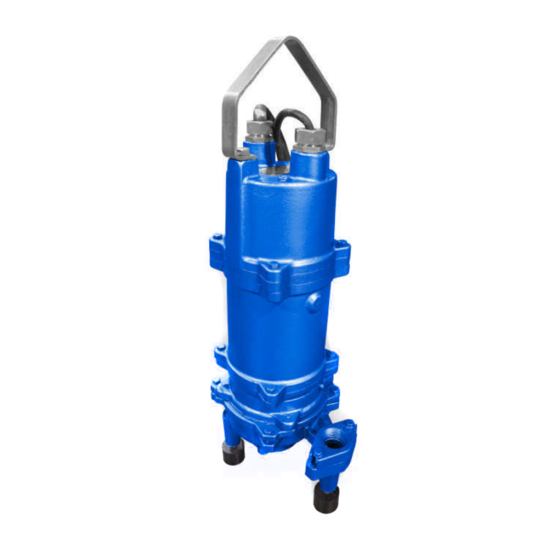
- Page 1 Installation, Operation & Maintenance Manual Submersible Grinder Pumps 1.25FFGP 2 HP @ 3450 RPM IMPORTANT! - Read all instructions in this manual before operating or servicing a pump.
-
Page 2: General Safety Information
IMPORTANT! - Flo Fab Pumps is not grease, strong chemicals, gasoline. responsible for losses, injury or... - Page 3 Speci cations & Dimensions DISCHARGE: 1¼" NPT, vertical. LIQUID TEMPERATURE: Continuous: 120° F (48° C) max. Intermittent: 140° F (60° C) max. VOLUTE: Cast iron ASTM A-48 class 30. MOTOR HOUSING: Cast iron ASTM A-48 class 30. SEAL PLATE: Cast iron ASTM A-48 class 30. IMPELLER: 12 vanes, vortex, with vanes on back side, dynamically balanced.
-
Page 4: Recommendations And Warnings
Recommendations and Warnings Receiving inspection The installation should be at a Upon receiving the pump, it should su cient depth to ensure that all Recommended inspected damage plumbing is below the frost line. If Submergence Level shortages. If damage has occurred, this is not feasible, remove the check le a claim immediately with the valve... -
Page 5: Installation & Service
Installation & Service Any splice between the pump and Moisture Sensors - A normally open the control panel must be made in (N/O) sensor rated of 1 watt @330K accordance with the electric codes. It ohms, 500 volt, is installed in the is recommended that a junction box, p ump seal chamber which will detect if used, be mounted outside the... - Page 6 Service Motor Power Cords IMPORTANT! - This pump is 2. Use a large screwdriver in the slot Pump models with seal leak detector not to be disassembled in shaft use a 5 conductor, #12 gauge cord. (counterclockwise) on one of the the eld except at certi ed The three power conductors are large cutter vanes with a hammer.
-
Page 7: Wiring Schematics
Wiring Schematics Figure 2 208/230 volts, single phase... - Page 8 Wiring Schematics Figure 3 208/230 volts, single phase...
- Page 9 Wiring Schematics Figure 4 230/460 volts, three phase...
-
Page 10: Repair Parts
Repair Parts Figure 5 P AR T L IS T ITE M QTY . DE S C R IP TION MATE R IAL P U MP C OVE R C AS T IR ON MOTOR H OU S IN G C AS T IR ON R OTOR B E AR IN G 6 2 0 5... -
Page 11: Troubleshooting Chart
NOTE: Flo Fab Pumps assumes no responsibility for damage or injury due to disassembly in the eld. Disassembly of the pumps or supplied accessories other than at Flo Fab Pumps or its authorized service centers, automatically voids warranty.
Need help?
Do you have a question about the 1.25FFGP Series and is the answer not in the manual?
Questions and answers