Table of Contents
Advertisement
Advertisement
Table of Contents

Related Manuals for Erbe EIP 2


Summary of Contents for Erbe EIP 2
- Page 1 SERVICE MANUAL EIP 2 V 1.0.x V 1.1.x ELECTROSURGERY 80116-261 2018-07...
- Page 3 SERVICE MANUAL EIP 2...
- Page 4 (by photocopying, microfilming or other methods) or processed, duplicated or dissem- inated by the use of electronic systems without the written consent of Erbe Elektromedizin GmbH. The information contained in this manual may be amended or supplemented without prior notice and represents no obli- gation on the part of Erbe Elektromedizin GmbH.
-
Page 5: Table Of Contents
Block diagram EIP 2 (120 V / 230 V) ....... . - Page 6 EIP 2 without ECB ........
-
Page 7: Safety Information
The supply voltage must match the voltage specified on the rating plate. Connect the unit / the equipment cart to a properly installed grounded outlet. Only use the Erbe power cord or an equivalent power cord for this purpose. The power cord must bear the national test sym- bol. -
Page 8: Electrostatically Sensitive Components
Liability and warranty ATTENTION! Adjustments, tests, modifications, maintenance and repair work may only be performed by Erbe or persons trained by Erbe. If the work is not performed by trained persons, Erbe accepts no liability and warranty rights become void. -
Page 9: Modifications
2 • Modifications CHAPTER 2 Modifications From V 1.1.x Hardware No changes Software Component affected Description of the modification Service programs New Service program: S 5 Automatic pressure control / 56... - Page 10 2 • Modifications / 56...
-
Page 11: Unit Description
A reset (= switching the unit back to the factory setting) is not possible. 1. ECB = Erbe Communication Bus for connecting the EIP 2 to a VIO electrosurgical unit. 2. Flow in % relative to the maximum flow of 500 ml/min. -
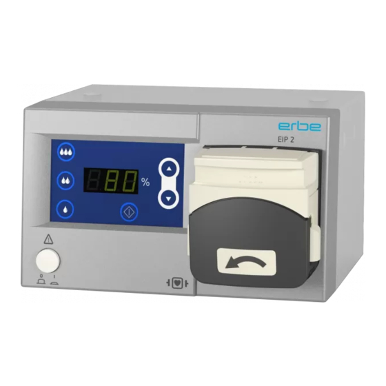
Page 12: Controls
3 • Unit description Controls IMPORTANT! This chapter contains an overview of the controls of the unit(s). The rel- evant User Manual for the unit(s), knowledge of which is assumed for servicing work, provides detailed information about how to use the unit(s). -
Page 13: Symbols
Never place your fingers in the pump head. Controls at the rear Fig. 3-2 Optional ECB socket (ECB = Erbe Communication Bus) for connecting the EIP 2 to a VIO electrosurgical unit Footswitch socket Potential equalization... -
Page 14: Description Of Function
Description of function Peristaltic pump principle The EIP 2 (Erbe Irrigation Pump) is a peristaltic pump. This operating prin- ciple is based on pressing or squeezing a flexible pump hose at one or more points and on movement of the squeezed point in the desired direc- tion of liquid flow. -
Page 15: Technical Data
4 • Technical Data CHAPTER 4 Technical Data Power supply for devices with 230 V Nominal line voltage Line current Power fuse Nominal line frequency 230 V ± 10% 200 mA T 0.2 A 50 / 60 Hz Power input in Standby Mode Power input at max. - Page 16 4 • Technical Data Dimensions and weight Width x height x depth 205 x 125 x 170 mm (without pump head) Width x height x depth 205 x 125 x 210 mm (with pump head) Weight 3 kg Ambient conditions for transport and storage of unit Temperature -40 °C to + 70 °C Relative humidity...
-
Page 17: Installation
5 • Installation CHAPTER 5 Installation Installation possibilities For EIP 2 (Erbe Irrigation Pump) there are three installation possibilities: • Installation on an Erbe VIO Cart. • Installation on an Erbe Universal Cart. • EIP 2 as a stand alone variant. - Page 18 5 • Installation / 56...
-
Page 19: Circuit Descriptions
6 • Circuit Descriptions CHAPTER 6 Circuit Descriptions / 56... -
Page 20: Block Diagram Eip 2 (120 V / 230 V)
6 • Circuit Descriptions Block diagram EIP 2 (120 V / 230 V) Fig. 6-1 / 56... -
Page 21: Block Diagram Eip 2 (100 V)
6 • Circuit Descriptions Block diagram EIP 2 (100 V) Fig. 6-2 / 56... -
Page 22: Beschreibung Der Einzelnen Baugruppen
Description of the various assemblies Line input The EIP 2 can be operated on line voltages of 230 V, 120 V, or 100 V. First of all the appropriate figure must be set, ±10 %, in the window of the volt- age selector switch on the main board. -
Page 23: Microcontroller
• Communication via a CAN interface with the VIO electrosurgical unit (only on units with ECB socket, ECB = Erbe Communication Bus). CAN module (optional) The CAN module enables communication between EIP 2 and the VIO elec- trosurgical unit. Footswitch The pump can be activated with the EIP 2 footswitch. - Page 24 6 • Circuit Descriptions / 56...
-
Page 25: Service Programs
Calling up service program mode When switching on the unit hold down the up / down buttons. On units with an ECB socket (ECB = Erbe Communication Bus) the service programs can be called up either by pressing the above button combina- tion or via CAN-ID. -
Page 26: Description Of Service Programs
7 • Service programs Description of service programs Service program S1 Flow test Description The S1 service program is used to check the flow of irrigation liquid over a period of 1 minute at a flow setting of 100 %. If the service program ends successfully, the message "CS1"... -
Page 27: Service Program S2 Led Test
7 • Service programs Service program S2 LED Test Description Service program S2 is used to check correct operation of all the LEDs on the control panel. Run time Not limited. Set value Not applicable. To activate the service program Press the activation button. -
Page 28: Service Program S3 Continuous Running / Burn-In
7 • Service programs Service program S3 Continuous running / Burn-In Description Service program S3 checks whether EIP 2 can withstand a substantial con- tinuous load. If the service program ends successfully, the message "CS3" (Complete Service Program 3) is output on the display. If a fault occurs during execu- tion, the message "ES3"... -
Page 29: Service Program S4 Version Output
7 • Service programs Service program S4 Version output Description Service program S4 indicates the software version of EIP 2. Run time Not limited. Set value Not applicable. To activate the service program Press the activation button. To abort the service program Press quick activation button III. -
Page 30: Service Program S5 Automatic Pressure Control
7 • Service programs Service program S5 Automatic pressure control Availability From software version 1.1.0. Description The automatic pressure control of the EIP 2 can be activated and deacti- vated with service program S5. Run time Not limited. Set value... -
Page 31: Remedying Malfunctions
ATTENTION! Adjustments, technical tests, modifications, maintenance and repair work may only be performed by Erbe or persons trained by Erbe. If the work is not performed by trained persons, Erbe accepts no liability and warranty rights become void. - Page 32 8 • Remedying malfunctions Error Possible cause Remedy Display E 5 CRC Check faulty. Due to various Change main board, influences such as ageing or radi- see page 44. ation the memory of the PIC may be altered. Display L 1 A quick activation button was Observe programming rules for programmed with flow that is too...
-
Page 33: Maintenance And Servicing
ATTENTION! Adjustments, tests, modifications, maintenance and repair work may only be performed by Erbe or persons trained by Erbe. If the work is not performed by trained persons, Erbe accepts no liability and warranty rights become void. It is recommended that the technical safety check also be performed by Erbe or persons trained by Erbe. -
Page 34: Technical Safety Check
Test equipment, measuring equipment, and auxiliary test equipment (cables, test boxes, etc.) are listed separately at the beginning of each test unit. Where Erbe article numbers are specified, only original Erbe test equipment, measuring equipment, and auxiliary test equipment may be used. -
Page 35: User Manual And Visual Inspections
Erbe Designation Art.-No. 20325-000 Footswitch for EIP 2 20325-001 Tubing set Erbe EIP 2 (100 V, 230 V) Test setup • The test specimen is connected to the power supply via the power cord. Test procedure Power switch 1. Check power switch for smooth operation. The power switch must be easy to operate and must neither stick nor scrape. - Page 36 9 • Maintenance and servicing 7-segment displays and LEDs 1. Start test specimen in service program mode and select service pro- gram S2. 2. Test 7-segment displays: All the segments on the three 7-segment displays should be an equally bright green color. 3.
-
Page 37: Replacing Components
ATTENTION! Adjustments, technical tests, modifications, maintenance and repair work may only be performed by Erbe or persons trained by Erbe. If the work is not performed by trained persons, Erbe accepts no liability and warranty rights become void. - Page 38 10 • Replacing components Fit new pump head 4. Fit new pump head in reverse order. / 56...
-
Page 39: Change Gear Motor
ATTENTION! Adjustments, technical tests, modifications, maintenance and repair work may only be performed by Erbe or persons trained by Erbe. If the work is not performed by trained persons, Erbe accepts no liability and warranty rights become void. - Page 40 10 • Replacing components Remove housing cover 4. Undo screws in the sub-base (2). 5. Undo screws in the rear panel (3). 6. Remove housing cover carefully, first upward and then to the rear. / 56...
- Page 41 10 • Replacing components Remove front frame 7. Undo screws in the frame (2). 8. Loosen nut (1) in the housing bottom. The nut can be removed com- pletely but does not have to be. 9. Pull away front frame toward the front as permitted by the display connector (not illustrated).
- Page 42 10 • Replacing components 10. Remove connectors J34, J35, and J10 from the main board and remove the front frame completely toward the front. / 56...
- Page 43 ATTENTION! Check line voltage setting The EIP 2 can be operated on a line voltage of 230 V, 120 V, or 100 V. Therefore, every time the unit is opened always check afterwards whether the correct line voltage ±10 % is set on the line voltage selec- tor switch on the main board.
-
Page 44: Change Main Board
ATTENTION! Adjustments, technical tests, modifications, maintenance and repair work may only be performed by Erbe or persons trained by Erbe. If the work is not performed by trained persons, Erbe accepts no liability and warranty rights become void. - Page 45 ATTENTION! Check line voltage setting The EIP 2 can be operated on a line voltage of 230 V, 120 V, or 100 V. Therefore, every time the unit is opened always check afterwards whether the correct line voltage ±10 % is set on the line voltage selec- tor switch on the main board.
- Page 46 10 • Replacing components / 56...
-
Page 47: Spare Parts
11 • Spare parts CHAPTER 11 Spare parts Abbreviations ECB = Erbe Communication Bus / 56... -
Page 48: Eip 2 Without Ecb
11 • Spare parts EIP 2 without ECB Fig. 11-1 / 56... - Page 49 11 • Spare parts Fig. 11-2 / 56...
- Page 50 11 • Spare parts Fig. 11-3 / 56...
- Page 51 11 • Spare parts Fig. 11-4 / 56...
-
Page 52: Eip 2 With Ecb
11 • Spare parts EIP 2 with ECB Fig. 11-5 / 56... - Page 53 11 • Spare parts Fig. 11-6 / 56...
- Page 54 11 • Spare parts Fig. 11-7 / 56...
- Page 55 11 • Spare parts Fig. 11-8 / 56...
- Page 56 11 • Spare parts / 56...
Need help?
Do you have a question about the EIP 2 and is the answer not in the manual?
Questions and answers