Table of Contents
Advertisement
Advertisement
Table of Contents

Related Manuals for Siemens IQHeat


Summary of Contents for Siemens IQHeat
- Page 1 IQHeat User manual Doc-1552 2019-01-30...
- Page 2 This manual is published by Cetetherm. Cetetherm can without further notice make changes and improvements to the content in this manual if it is necessary due to printing mistakes, wrong information or changes in the hardware or software. All these types of changes will be included in future release of the manual.
-
Page 3: Table Of Contents
IQHeat User manual Contents General ..........................3 Information about this document .......................3 Product overview IQHeat cabinets ......................4 DDC1; Processing unit with Display and TCP/IP interface ...............4 Communication principles ....................5 Internal Interface............................5 2.1.1 LEDs for BSP and BUS diagnostics .....................5 2.1.2... - Page 4 Testing the pumps ..........................35 10.3 Testing the valves ..........................35 Exceptions calendar ......................36 11.1 Exceptions calendar ..........................36 Services for IQHeat ......................38 12.1 Standard services ........................... 38 12.2 Optional services ............................ 38 Troubleshooting ........................39 Options ..........................40 14.1...
-
Page 5: General
• BacNet and LON as well as ModBus give you the option of controlling IQHeat from the central building automation system. IQHeat has always a temperature sensor on the primary side supply and return, and on the secondary side supply and return. -
Page 6: Product Overview Iqheat Cabinets
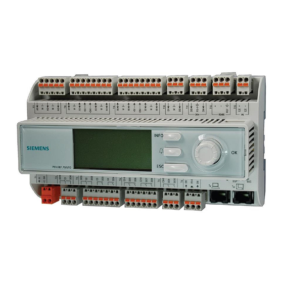
IQHeat User manual Product overview IQHeat cabinets For information about the included components, see the respective product documentation. DDC1; Processing unit with Display and TCP/IP interface DDC 1, Processing unit is fitted with an integral control panel where the plant values can be read and set. -
Page 7: Communication Principles
IQHeat User manual 2 Communication principles Internal Interface A ModBus interface is always available in the processing unit. The RS485 interface can be defined as master or slave; if both master and slave are required, a communication module must be connected with ModBus. -
Page 8: Upgrade With Sd Card
IQHeat User manual BUS LED This LED only indicates the status of the integrated modem communication. The LED does not indicate the status of internal communication (for input/output modules or communication modules). This status is displayed on each expansion module. -
Page 9: The Control Panel
IQHeat User manual 3 The control panel All images in this document, in the menus in the control panel, are simply example images and should not be used as a basis for settings. The control panel is integrated into the processing unit. -
Page 10: Display Layout
IQHeat User manual Display layout a) current privilege level: • no symbol - no privilege level • one key - privilege level 6 • two keys - privilege level 4 • three keys - privilege level 2. b) title for the displayed page... -
Page 11: Setting Parameters
IQHeat User manual Settings bar: A setting bar shows the parameter name and the current value on a black background. Setting value: • select the line: turn the navigation dial • switch settings page: press the navigation dial • set parameter value: turn the navigation dial •... -
Page 12: Log In And Set The Clock
Password and login The controller has password protection, allowing access to different menus. NOTE: For security reasons must the factory set password be changed the first time the IQHeat starts up. The following log-in levels are available: All users: no log-in, no password required •... -
Page 13: Time Functions Setting Of Time And Date
IQHeat User manual Time functions setting of time and date The controller's clock includes the functions for summer and winter time changes and leap years. The clock has a backup function to cover at least 24 hours of power cuts. -
Page 14: Alarm Management
IQHeat User manual 5 Alarm management The processing unit alerts for different situations. Alarms are indicated on the control display with the alarm symbol Alarms are divided into three classes: • A or 1 = Alarm, High • B or 2 = Alarm, Low •... -
Page 15: Alarm History
IQHeat User manual 4. To see detailed information about an alarm, select the desired alarm by using the navigation dial and press OK. All active alarms have the following information included in the Alarm list. + Alarm name Status Alarm class... -
Page 16: Alarms And Their Classification
IQHeat User manual Alarms and their classification All sensors use function alarms that are enabled when, for example, there is a cable break or short circuit. On top of this, there are several different types of level alarms; high-level and low-level where the size of the sensors' level can be limited. -
Page 17: General Functions
IQHeat User manual 6 General functions Reading the current temperatures and valve modes 1. Press Info to access Main overview. 2. Here you can see information about the connected heating circuit and hot water circuit. 3. Scroll down in the menu with the navigation dial. -
Page 18: System Objects
IQHeat User manual System objects NOTE: Access to the menys in this section requirer login at end user level. 6.3.1 Plant information Information about the plant name, location address and versions of component parts can be read in the System parameters menu: 1. -
Page 19: Heating Circuit
User manual 7 Heating circuit IQHeat gives you the option of making settings for various daily and weekly programs. These can be used, for example, as automatic night lowering of the flow temperature and thereby the indoor temperature. The time program that appears under Common cannot be used to control the heating circuits. -
Page 20: Heat Time Program
IQHeat User manual Heat time program Each heating circuit can have six different time sets per day in the week. For each time, one of three modes; build protection, economy and comfort, can be selected that are then in effect until the next time occurs. If only one time is set, the circuit will always run with the selected mode. -
Page 21: Setting The Value For The Heating Circuit
IQHeat User manual Setting the value for the heating circuit 1. Press Info to access the Main index. 2. Select Heating Circuit and press OK. 3. Select the parameter to be changed and press OK. 4. Set the desired value with the navigation dial, press OK. -
Page 22: Heating Limit Eco
IQHeat User manual A curve that is set too low means that the heat will not be sufficient, that the secondary flows are too high. A curve that is set too high results in unnecessary energy losses and can lead to excess temperatures in parts of the buildings that are not adjusted for low flows. -
Page 23: Setting Heating Limit (Eco)
IQHeat User manual 7.5.1 Setting Heating limit (ECO) NOTE: Setting the Heating limit (ECO) requires logging at Service level. 1. Press Info to access the Main index. 2. Now select Commissioning > Plant settings > Heating circuit1 or just choose Heating circuit in the Main Index menu. -
Page 24: Parallel Offset Of Heating Curve
IQHeat User manual Parallel offset of heating curve The set heating curve can, if necessary, be parallel offset. NOTE: Parallel offsetting of the heating curve requires login at Service level. 1. Press Info to access the Main index. 2. Now select Commissioning > Plant settings. >... -
Page 25: Hot Water Circuit
IQHeat User manual 8 Hot water circuit NOTE: All settings done in this chapter require login at end-user level. Hot water operating mode The hot water circuit can be set in one of four operating modes: • Auto - plant uses the set Set point and can be controlled via an external communication interface. To activate the legionella function, you must select the Auto mode. -
Page 26: Service Level
IQHeat User manual 9 Service level NOTE: The following settings and tests require logging in at Service level. Change password 1. From the Main index select Systemobjects. 2. Now select Password handling > Change password. 3. Select the password to be changed and press OK. -
Page 27: Frost Protection
IQHeat User manual Frost protection The frost protection function can be switched off and on. You can also change the temperature Setp.plant frost. 1. From the Main index select Commissioning. 2. Now select Plant settings > Common. 3. Select the parameter to be changed and press OK. -
Page 28: Pump And Valve Exercising
Save and reset start-up settings and factory settings The first time IQHeat is started, the Service settings and Factory settings are the same. After adjustment of the plant-specific parameters such as heating curve, time programs and the like, it is useful to save these settings for later use if something goes wrong. -
Page 29: Setting Up And Activating The Legionella Function
IQHeat User manual Setting up and activating the legionella function The legionella function is not enabled from the factory. The set point for legionella must never exceed the temperature for district heating supply. If the legionella set point is set too close to or above the supply temperature, this may result in a fully open control valve and thereby large district heat flows. -
Page 30: Change Alarm Limits For Heating, Cooling And Hot Water Circuits
IQHeat User manual Change alarm limits for heating, cooling and hot water circuits Alarm limits for flow temperature, return temperature and deviation alarms for flow temperature can be set per preferences. The change is made in the same way as for heating, cooling, and hot water circuits. -
Page 31: Settings Hot Water Circuit
IQHeat User manual Settings hot water circuit 1. From the Main index select Commissioning. 2. Now select Plant config> Domestic hot water. 3. Select the parameter to be changed, press OK. 4. Return to Plant config. 5. Select Restart, press OK. -
Page 32: Communication Settings
IQHeat User manual 5. Go back to the SMS menu and select SMS number. 6. For information on settings made in the time program see 7.2.Heat time program. Instead of operating mode, the telephone numbers in time program for SMS numbers are listed. -
Page 33: Set Ip Address, Ip Mask And Gateway For Web Onboard
IQHeat User manual 9.10.2 Set IP address, IP mask and Gateway for Web onboard Here is a description of how to set the IP address. The IP Mask and Gateway are set in the same way. 1. From the Main index select Systemobjects. -
Page 34: Read And Change The Mbus Parameters
IQHeat User manual 9.11 Read and change the MBus parameters To check that the serial number on the integrator matches the set address parameters in the processing unit. See Main index > Communication > Communic.modules > 2-M-Bus module. Also, check that a value is received from the heat meter. -
Page 35: Tcp/Ip
IQHeat User manual 9.12.2 TCP/IP For ModBus across IP; check the address to the processing unit, and use port 502 in the master system. 1. From the Main index select Systemobjects. 2. Now select Communication > ModBus > IP-Config. 3. Select the parameter to be changed, press 4. -
Page 36: Tests
IQHeat User manual 10 Tests NOTE: All tests require login at Service level. 10.1 Testing the wirings All cables are tested simultaneously. The test shows whether the sensors with their connections are correct. NOTE: Wiring test is active until it is set to Passive. For the control to work, the cable test in normal operation must be set to Passive. -
Page 37: Testing The Pumps
IQHeat User manual 10.2 Testing the pumps All the pumps are tested in the same manner. Here is a description of the test of the hot water pump. Wiring test must be Active when testing the pumps. The test shows if the pumps and their control are correctly connected. -
Page 38: Exceptions Calendar
IQHeat User manual 11 Exceptions calendar 11.1 Exceptions calendar Exception days can be defined in the Calendar contained in the Common menu. The calendar controls the exceptions that can be selected in the Time program for the heating circuits and cooling circuit. - Page 39 IQHeat User manual Parameter Factory Settings Relates to settings range End date * ,* .* .** * ,* .* .** Sel x = • Mon…Sun range: Enter • 01…31, ld end date for • the period. Jan...Dec, The end date...
-
Page 40: Services For Iqheat
Services related to an additional hardware or software and that can be ordered as an option. Communication in the basic package for IQHeat is ModBus RTU, a modem port and a simple WEB. You can also use ModBus IP through the WEB function. -
Page 41: Troubleshooting
IQHeat User manual 13 Troubleshooting Symptom Cause Action Hot water The set point is incorrect Adjust the HW set point temperature too Control valve not working Check that the valve is working by running in manual mode from the control unit up/down, or check to see if the valve reacts to changes to the set point. -
Page 42: Options
MBus: For connection of thermal flow meter with M-Bus communications. • LON: Allows you to connect IQHeat to a LON network. How many and which of these optional modules that can be connected simultaneously or totally depends on the type of district heating and cooling substations. -
Page 43: Setting Expansion Module's Dip Switches
With two expansion modules expansion module (first and then second, IQHeat120) (standard IQHeat 50, 100, 110) 14.1.2 LEDs for BSP and BUS diagnostics The expansion module has two LEDs, BSP and BUS, for diagnostics. The LEDs can light with three different colours: yellow, green and red. -
Page 44: Communication Module Web, Adv. Web
IQHeat User manual 14.2 Communication module Web, Adv. Web The communication module is used to activate the advanced web functionality of the processing unit. It is therefore called Advanced Web module, Adv.Web. The Adv Web module has the following characteristics: •... -
Page 45: Leds For Bsp And Bus Diagnostics
IQHeat User manual 14.6 LEDs for BSP and BUS diagnostics Optional modules have two LEDs for diagnostics. The LEDs can light with three different colours: yellow, green and red. LEDs for BSP and BUS diagnostics The BSP LED has the same meaning for all modules. -
Page 46: Overview Of Available Menus
IQHeat User manual 15 Overview of available menus The following menus are available when logging in at End User Level. - Page 47 IQHeat User manual...
- Page 48 Cetetherm AB Fridhemsvägen 15 372 38 Ronneby – Sweden www.cetetherm.com...
Need help?
Do you have a question about the IQHeat and is the answer not in the manual?
Questions and answers