KAESER ASK T series Service Manual

KAESER ASK T series Service Manual

Screw compressor. sigma control basic
Table of Contents

Advertisement

Quick Links

Service Manual
Screw Compressor
ASK T
SIGMA CONTROL BASIC
9_5717 20 E
Manufacturer:
KAESER KOMPRESSOREN GmbH
96410 Coburg • PO Box 2143 • GERMANY • Tel. +49-(0)9561-6400 • Fax +49-(0)9561-640130
http://www.kaeser.com

Advertisement

Table of Contents
loading
Need help?

Need help?

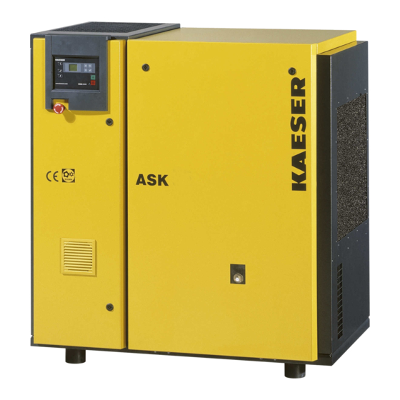
Do you have a question about the ASK T series and is the answer not in the manual?

Questions and answers

David Ramírez
March 6, 2025

¿Como puedo levantar la presión de aire del compresor?

1 comments:
Mr. Anderson
March 6, 2025

To increase the air pressure of the KAESER ASK T series compressor, follow these steps:

1. Check for Back Pressure: Ensure there is no build-up of back pressure, which can prevent proper venting. If present, change over phase lines L1 and L2 or replace drive belts.

2. Inspect the Minimum Pressure Valve: A faulty valve can limit pressure buildup. Check and replace it if necessary.

3. Verify Motor Rotation: Incorrect motor rotation can affect compressor performance. Ensure the motor is rotating in the correct direction.

4. Ensure Proper Venting: If the compressor is not venting correctly at standstill, inspect and rectify any venting issues.

5. Check the Back-Pressure Switch: A defective back-pressure switch may cause pressure issues. Replace it if needed.

6. Maintain Cooling System: Overheating can reduce efficiency. Clean the radiator and refrigerant condenser, ensure adequate ventilation, and check the cooling oil level.

7. Use Only Genuine KAESER Parts: Ensure all replacement parts, including pressure-bearing components and filters, are KAESER-approved.

If these steps do not resolve the issue, consult an authorized KAESER service technician for further troubleshooting.

This answer is automatically generated

Subscribe to Our Youtube Channel

Summary of Contents for KAESER ASK T series

  • Page 1 Service Manual Screw Compressor ASK T SIGMA CONTROL BASIC 9_5717 20 E Manufacturer: KAESER KOMPRESSOREN GmbH 96410 Coburg • PO Box 2143 • GERMANY • Tel. +49-(0)9561-6400 • Fax +49-(0)9561-640130 http://www.kaeser.com...
  • Page 2 Original instructions /KKW/SASK 2.00 en SBA-SCHRAUBEN-T-SCB 20111103 144508...
  • Page 3: Table Of Contents

    Contents Regarding this document Using this document ......................Further documents ......................Copyright .......................... Symbols and labels ......................1.4.1 Warnings ......................1.4.2 Potential damage warnings ................1.4.3 Other alerts and their symbols ................Technical Specifications Nameplate ........................Options ..........................Weight ..........................Temperature ........................
  • Page 4 Contents Floating relay contacts ..................... Options ..........................4.5.1 Machine mountings ..................... 4.5.2 Prepared for external heat recovery ..............Operating modes and control modes ................4.6.1 Operating modes ....................4.6.2 Control modes ....................Refrigeration Dryer Control Modes .................. Safety devices ........................Keys and LEDs –...
  • Page 5 10.19 Documenting maintenance and service work ..............Spares, Operating Materials, Service 11.1 Note the Nameplate ......................11.2 Ordering consumable parts and operating fluids/materials ..........11.3 KAESER AIR SERVICE ....................11.4 Service Addresses ......................11.5 Spare Parts for Service and Repair ................. Decommissioning, Storage and Transport 12.1 Putting Out of Operation ....................
  • Page 6 Contents 13.4 Electrical Diagram ......................108 Service Manual Screw Compressor ASK T SIGMA CONTROL BASIC 9_5717 20 E...
  • Page 7 List of Illustrations Fig. 1 Maximum relative humidity of intake air ..................Fig. 2 Location of safety signs ......................Fig. 3 Enclosure overview ........................Fig. 4 Machine layout ........................... Fig. 5 Refrigeration dryer ........................Fig. 6 Machine mountings ........................Fig. 7 Keys –...
  • Page 8 List of Illustrations Service Manual Screw Compressor ASK T SIGMA CONTROL BASIC 9_5717 20 E...
  • Page 9 List of Tables Tab. 1 Danger levels and their definition (personal injury) ..............Tab. 2 Danger levels and their definition (damage to property) ............Tab. 3 Nameplate ..........................Tab. 4 Options ............................Tab. 5 Machine weight .......................... Tab. 6 Temperature ..........................Tab.
  • Page 10 List of Tables Tab. 55 Permissible cooling oil level under LOAD ................. Tab. 56 Logged maintenance tasks ......................Tab. 57 Consumable parts ........................Service Manual Screw Compressor viii ASK T SIGMA CONTROL BASIC 9_5717 20 E...
  • Page 11: Regarding This Document Using This Document

    Copyright This service manual is copyright protected. Queries regarding use or duplication of the documenta‐ tion should be referred to KAESER. Correct use of information will be fully supported. Symbols and labels ➤ Please note the symbols and labels used in this document.
  • Page 12: Potential Damage Warnings

    Regarding this document Symbols and labels DANGER The type and source of the imminent danger is shown here! The possible consequences of ignoring a warning are shown here. If you ignore the warning notice, the "DANGER" signal word indicates a lethal or severe in‐ jury will occur.
  • Page 13 Regarding this document Symbols and labels Material Here you will find details on special tools, operating materials or spare parts. Precondition Here you will find conditional requirements necessary to carry out the task. The conditions relevant to safety shown here will help you to avoid dangerous situations. Option H1 ➤...
  • Page 14: Technical Specifications Nameplate

    Technical Specifications Nameplate 2 Technical Specifications Nameplate The machine's nameplate provides the model designation and important technical information. The nameplate is located on the outside of the machine: ■ above the cooler, ■ on the rear of the machine. ➤ Enter here the nameplate data as a reference: Feature Value Rotary Screw Compressor...
  • Page 15: Temperature

    Technical Specifications Temperature ASK 27 ASK 32 ASK 35 Weight [kg] Tab. 5 Machine weight Temperature ASK 27 ASK 32 ASK 35 Minimum cut-in tempera‐ ture [°C] Typical airend discharge 65 – 100 65 – 100 65 – 100 temperature during oper‐ ation [°C] Maximum airend dis‐...
  • Page 16: Ventilation

    Technical Specifications Ventilation Fig. 1 Maximum relative humidity of intake air Intake air temperature [°C] Maximum relative humidity of intake air [%] Ventilation The values given are minimum guide values. Mains frequency: 50 Hz ASK 27 ASK 32 ASK 35 Inlet aperture see fig‐...
  • Page 17: Delivery

    Technical Specifications Delivery Pressure relief valve activating pressure at 50Hz [bar] Maximum working over‐ ASK 27 ASK 32 ASK 35 pressure [bar] 11.0 15.0 * China: 15.9 Tab. 10 Pressure relief valve activating pressure (50Hz) Pressure relief valve activating pressure at 60 Hz [bar] Maximum working over‐...
  • Page 18: Noise Emission [Db(A)]

    Technical Specifications Noise emission [dB(A)] Noise emission [dB(A)] Mains frequency ASK 27 ASK 32 ASK 35 50 Hz 60 Hz Noise pressure level as per ISO 2151 and the basic standard ISO 9614-2, tolerance: ±3 dB(A) at maximum machine working pressure Tab.
  • Page 19: Tab. 18 Cooling Oil Recommendation

    Technical Specifications 2.11 Cooling oil recommendation Cooling oils for general applications SIGMA FLUID S-460 S-570 Description Mineral oil Silicone-free Synthetic oil synthetic oil Application: Standard oil for all appli‐ Standard oil for all applications Standard oil for East- / cations except in con‐ except in connection with food‐...
  • Page 20: Cooling Oil Charge

    Technical Specifications 2.12 Cooling oil charge SIGMA FLUID FG-460 FG-680 Flash point 245 °C 245 °C (D 92; ASTM test) (D 92; ASTM test) Density at 15 °C — — Pour point — — Demulsibility at — — 54 °C Tab.
  • Page 21: Power Supply

    Technical Specifications 2.13 Power Supply Option W1 Heat recovery The additional volume corresponds to the oil volume of the heat exchanger and the connecting lines: ASK 27 ASK 32 ASK 35 Additional charge vol‐ ume [l]* * Enter the volume required by your heat recovery system. Tab.
  • Page 22: Mains Frequency: 50 Hz

    Technical Specifications 2.14 Power supply specifications ➤ For other application conditions, check conductor diameters and change accordingly. Other conditions would include, for example: ■ Higher temperature ■ Other cable installation method ■ Cable length >50 m 2.14.1 Mains frequency: 50 Hz Rated voltage: 200V±10%/3/50Hz ASK 27 ASK 32...
  • Page 23: Mains Frequency: 60 Hz

    Technical Specifications 2.14 Power supply specifications The operator must ensure that the machines are only connected to a network that meets these re‐ quirements. If necessary, ask the local electricity company for the value of the network impedance. ASK 27 ASK 32 ASK 35 Anticipated number of...
  • Page 24: Available Heat Capacity

    Technical Specifications 2.15 Available heat capacity ASK 27 ASK 32 ASK 35 Current input [A] Tab. 30 Mains supply 460V/3/60Hz 2.15 Option W1 Available heat capacity The quality of the heat transfer medium and its required flow rate depend on the type of heat exchanger used.
  • Page 25: Tab. 34 Refrigeration Dryer: Refrigerant Circuit

    Technical Specifications 2.16 Refrigeration dryers ABT 27 ABT 32 Refrigerant R 134a R 134a Global warming potential 1300 1300 (GWP) Charge quantity* [kg] Maximum permitted working pressure [bar] (high pressure end) Maximum permitted working pressure [bar] (low pressure end) Safety pressure switch: Cut-out pressure [bar] * Read off the charge quantity from the dryer nameplate and enter it in the table.
  • Page 26: Safety And Responsibility Basic Instructions

    Safety and Responsibility Basic instructions 3 Safety and Responsibility Basic instructions The machine is manufactured to the latest engineering standards and acknowledged safety regula‐ tions. Nevertheless, dangers can arise through its operation: ■ danger to life and limb of the operator or third parties, ■...
  • Page 27: Qualified Personnel

    Safety and Responsibility User's Responsibilities ➤ Observe relevant statutory and accepted regulations during installation, operation and mainte‐ nance of the machine. 3.4.2 Qualified personnel These are people who, by virtue of their training, knowledge and experience as well as their knowl‐ edge of relevant regulations can assess the work to be done and recognise the possible dangers involved.
  • Page 28: Dangers

    Approved supervisory body ment inspection Internal inspection Every 5 years after installation or the Competent person last inspection (e. g. KAESER Service Technician) Strength test Every 10 years after installation or Competent person the last inspection (e. g. KAESER Service Technician) Tab.
  • Page 29 Safety and Responsibility Dangers ➤ De-pressurise all pressurised components and enclosures. ➤ Do not carry out welding, heat treatment or mechanical modifications on pressurised compo‐ nents (e.g. pipes and vessels) as this influences the component's resistance to pressure. The safety of the machine is then no longer ensured. Compressed air quality The composition of the compressed air must be suitable for the actual application in order to pre‐...
  • Page 30: Safe Machine Operation

    Unsuitable spare parts compromise the safety of the machine. ➤ Use only spare parts approved by the manufacturer for use in this machine. ➤ Use only genuine KAESER replacement parts on pressure bearing parts. Conversion or modification of the machine Modifications, additions to and conversions of the machine or the controller can result in unpredict‐...
  • Page 31 Safety and Responsibility Dangers ■ Safety boots ■ Eye protection ■ Ear protection Transporting The weight and size of the machine require safety measures during its transport to prevent acci‐ dents. ➤ Use suitable lifting gear that conforms to local safety regulations. ➤...
  • Page 32: Organisational Measures

    ➤ Do not open the cabinet while the machine is switched on. ➤ Do not open or dismantle any valves. ➤ Use only spare parts approved by KAESER for use in this machine. ➤ Carry out regular inspections: for visible damages,...
  • Page 33: Safety Devices

    Safety and Responsibility Safety devices Activity Danger area Authorised personnel Transport Within a 3 m radius of the machine. Installation personnel for transport preparation. No personnel during transport. Beneath the lifted machine. No personnel! Installation Within the machine. Installation personnel Within 1 m radius of the machine and its sup‐...
  • Page 34: Emergency Situations

    Safety and Responsibility Emergency situations Item Symbol Meaning Danger of fatal injury from electric shock! ➤ Before starting any work on electrical equipment: Switch off and lock out the power supply disconnecting device and verify the ab‐ sence of any voltage. Hot surface! Risk of burns caused by contact with hot components ➤...
  • Page 35: Treating Injuries From Handling Cooling Oil

    Safety and Responsibility Emergency situations Extinguishing substances ➤ Suitable extinguishing media: Foam Carbon dioxide Sand or soil ➤ Unsuitable extinguishing media: Strong jet of water 3.8.2 Treating injuries from handling cooling oil Eye contact: Cooling oil can cause irritation. ➤ Rinse open eyes thoroughly for a few minutes under running water. ➤...
  • Page 36: Warranty

    ■ incorrect maintenance, ■ incorrect repair. Correct maintenance and repair includes the use of genuine KAESER spare parts and operating materials. ➤ Obtain confirmation from KAESER that your specific operating conditions are suitable. 3.10 Environment protection The operation of this machine may cause dangers for the environment.
  • Page 37: Design And Function

    Design and Function Enclosure 4 Design and Function Enclosure Fig. 3 Enclosure overview Control cabinet door Sight glass: Oil level indicator Latch Sight glass: Condensate drain Panel (removable) When closed, the enclosure serves various functions: ■ Sound insulation ■ Protection against contact with components ■...
  • Page 38: Machine Function

    Design and Function Machine function Machine function Fig. 4 Machine layout Inlet valve Control cabinet Minimum pressure/check valve Oil separator tank Compressor motor Air filter Oil filter Oil/air cooler Airend Add-on cabinet for refrigeration dryer Ambient air is cleaned as it is drawn in through the filter The air is then compressed in the airend The airend is driven by an electric motor Cooling oil is injected into the airend.
  • Page 39: Refrigeration Dryer

    Design and Function Refrigeration dryer Refrigeration dryer Fig. 5 Refrigeration dryer Refrigeration dryer Condensate drain The downstream refrigeration dryer removes moisture from the compressed air. The condensate drain ejects the precipitate. Floating relay contacts Floating relay contacts are provided for the transfer of signals, messages. Information on location, loading capacity and type of message or signal is found in the electrical diagram.
  • Page 40: Prepared For External Heat Recovery

    Operating elements are marked with their opening temperature [°C]. If the cooling oil temperature is too low, condensate can form and damage the machine. ➤ Consult KAESER Service on components and layout to ensure proper functioning of the cooling and heat recovery systems.
  • Page 41: Control Modes

    The load and power consumption of the drive motor rises and falls with the air demand. The regulating valve is factory set. The setting should not be changed without consultation with KAESER SERVICE. 4.6.2 Control modes Using the selected control mode, the controller switches the machine between its various opera‐...
  • Page 42: Refrigeration Dryer Control Modes

    Design and Function Refrigeration Dryer Control Modes QUADRO In contrast to the the DUAL regulating mode, the machine will switch from LOAD to STANDSTILL in QUADRO mode after periods with low compressed air consumption. After periods with a high compressed air consumption, the machine will switch from LOAD to STANDSTILL after passing through IDLE.
  • Page 43: Safety Devices

    Design and Function Safety devices Safety devices The following safety devices are provided and may not be modified in any way. ■ EMERGENCY STOP control device: The EMERGENCY STOP button shuts down the compressor immediately. The motor remains stopped. The pressure system is vented. ■...
  • Page 44: Functional Description - Sigma Control Basic

    Design and Function 4.10 Functional description – SIGMA CONTROL BASIC Item Name Function «Enter» Enters edit mode. Exits the edit mode and saves. Only affects the value in the third line of the display. Tab. 41 Keys Fig. 8 Indicators Item Name Function Indicator field or display...
  • Page 45: Parameters

    Parameters Meaning Operating hours counter Displays the total time the drive motor was switched on. Only KAESER Service has the right to change this parameter. Load hours counter Shows the total time the compressor drive motor has run under LOAD.
  • Page 46: Messages

    Setting range [bar]: 5.5 ... maximum operating overpressure maximum possible setpoint pressure setting Only KAESER Service has the right to change this parameter. Options The displayed value informs KAESER Service concerning the controller's internal machine configuration.
  • Page 47: Installation And Operating Conditions

    The distances quoted are recommended distances and ensure unhindered access to all ma‐ chine parts. ➤ Please consult KAESER if you cannot comply with these recommendations. Precondition The floor must be level, firm and capable of bearing the weight of the machine.
  • Page 48: Ensuring The Machine Room Ventilation

    It evacuates the exhaust heat of the machine and thus ensures the required operating condi‐ tions. ➤ Consult with KAESER if you cannot ensure the conditions for an adequate ventilation of the machine room. 1. Ensure that the volume of air flowing into the machine room is at least equivalent to that being removed from it by the machine and exhaust fan.
  • Page 49: Exhaust Duct Design

    The machine can only overcome the air resistance at the cooling air inlet and exhaust determined by the duct design. Any additional air resistance will reduce airflow and deteriorate machine cool‐ ing. ➤ Consult the KAESER service representative before deciding on: ■ the design of the exhaust air ducting ■...
  • Page 50: Installation

    Installation Ensuring safety 6 Installation Ensuring safety Follow the instructions below for safe installation. Warning instructions are located before a potentially dangerous task. Disregard of warning instructions can cause serious injuries! Complying with safety notes Disregard of safety notes can cause unforeseeable dangers! ➤...
  • Page 51: Reporting Transport Damage

    ➤ Install only corrosion-resistant pipes. ➤ Use fluoroelastomers as sealing material for seals. ➤ Note the electro-chemical voltage sequence. ➤ Consult with KAESER for suitable materials for the compressed air network. Precondition The compressed air system is vented completely to atmospheric pressure.
  • Page 52: Refrigeration Dryer: Connecting The Transformer According To The Mains Supply

    Installation Connecting the Condensate Drain 1. The power supply must only be connected by authorised installation personnel or an author‐ ised electrician. 2. Carry out safety measures as stipulated in relevant regulations (IEC 364, for example or DIN VDE 0100) and in national accident prevention regulations (BGV A3 in Germany). In addi‐ tion, observe the regulations of the local electricity supplier.
  • Page 53: Connecting The Remote Load-Idle Control

    Installation Connecting the remote LOAD-IDLE control Fig. 11 Condensate drain dimensions [mm] Threaded connection Condensate collecting line ➤ Connect the condensate hose. ➤ Collect the condensate in a suitable container and dispose of in accordance with environ‐ mental regulations. Further information The dimensional drawing in chapter 13.3 gives the size and position of the condensate drainage connection ports.
  • Page 54: Options

    An unsuitable heat exchanger or incorrect installation may influence the cooling oil circuit within the compressor. Damage to the machine will follow. ➤ Consult KAESER on a suitable heat exchanger and have KAESER Service do the installation. Service Manual Screw Compressor...
  • Page 55: Initial Start-Up Ensuring Safety

    Initial Start-up Ensuring safety 7 Initial Start-up Ensuring safety Here you will find instructions for a safe commissioning of the machine. Warning instructions are located before a potentially dangerous task. Disregard of warning instructions can cause serious injuries! Complying with safety notes Disregard of safety notes can cause unforeseeable dangers! ➤...
  • Page 56: Instructions To Be Observed Before Commissioning Or Re-Commissioning

    ➤ Change the oil filter. ➤ Change the oil separator cartridge. ➤ Change the cooling oil. ➤ Have the motor bearings checked by an authorised KAESER Service Tech‐ nician. 36 months ➤ Have the overall technical condition checked by an authorised KAESER Service Technician.
  • Page 57: Setting The Overload Protection Cut-Out

    ➤ Check the overload protection cut-out setting. The overload protection cut-out shuts the machine down despite being correctly set? ➤ Contact KAESER Service. Pouring cooling oil into the airend Before starting the compressor for the very first time and before re-starting after a shutdown period of more than 3 months it is necessary to manually add a quantity of cooling oil into the airend.
  • Page 58: Activating And Deactivating The Modulating Control

    Initial Start-up Activating and deactivating the MODULATING control Fig. 13 Inlet valve filling port Screw plug Inlet valve 1. Unscrew the filler plug from the inlet valve. 2. Pour the stipulated amount of cooling oil into the airend and replace the filler plug. 3.
  • Page 59: Checking The Door Interlock Switch

    ➤ Open or close the control valve, depending on the required control mode. The control valve is factory set. The setting should not be changed without consultation with KAESER Service. Checking the Door Interlock Switch The interlock switch stops the machine as soon as the front access panel is opened.
  • Page 60: Starting The Machine For The First Time

    The machine shuts down automatically. The controller displays an alarm message. 2. Close the panel and acknowledge the alarm. The machine does not shut down? ➤ Have the interlock switch checked by an authorised KAESER Service representative. Starting the machine for the first time Precondition No personnel are working on the machine.
  • Page 61 Initial Start-up Setting the setpoint pressure Setpoint pressure: switching differential This switching differential is factory set. Adjust this parameter if the motor starting frequency is too high. 1. Scroll with the arrow keys until the parameter C "setpoint pressure: switching differential" is dis‐ played in line 3.
  • Page 62: Operation

    Operation Switching On and Off 8 Operation Switching On and Off Always switch the machine on with the «ON» key and off with the «OFF» key. A power supply disconnecting device has been installed by the user. Fig. 16 Switching On and Off Machine ON LED (green) «OFF»...
  • Page 63: Switching Off In An Emergency And Switching On Again

    Operation Switching off in an emergency and switching on again LOAD IDLE The machine switches to IDLE. The motor stops immediately. Machine ON LED flashes. Machine ON LED extinguishes. The drive motor comes to a stop after about 15 seconds. Machine ON LED extinguishes.
  • Page 64: Setting Parameters

    Operation Setting parameters Setting parameters If a password is needed it is requested automatically. Every action can be cancelled with the «escape» key. If no key is pressed for ten seconds in the edit mode, the display automatically returns to the previous mode.
  • Page 65: Acknowledging Alarm And Warning Messages

    Operation Acknowledging alarm and warning messages Acknowledging alarm and warning messages Fig. 18 Acknowledging messages Warning LED (yellow) Alarm LED (red) «Acknowledge» key Alarm message Messages are displayed on the "new value" principle: ■ Message received: LED flashes ■ Message acknowledged: LED lights ■...
  • Page 66: Fault Recognition And Rectification

    1. Do not attempt fault rectification measures other than those given in this manual! 2. In all other cases: Have the fault rectified by an authorized KAESER service representative. Alarm messages (machine shut down) The fault code appears in the 4th line of the display field.
  • Page 67: Warning Messages

    Fault Recognition and Rectification Warning messages Fault Symbol Meaning Remedy code Maximum permissible airend dis‐ ➤ Clean the radiator. charge temperature exceeded. ➤ Maintain sufficient distance between the cooling air inlet and exhaust openings and any wall. Check the cooling oil level. ➤...
  • Page 68: Other Faults

    Other Faults Other Faults Fault Possible cause Remedy Machine runs but produces no Inlet valve not opening or only Call KAESER service represen‐ compressed air. opening partially. tative. Venting valve not closing. Call KAESER service represen‐ tative. Leaks in the pressure system.
  • Page 69: 10.1 Maintenance

    Maintenance 10.1 Ensuring safety 10 Maintenance 10.1 Ensuring safety Follow the instructions below for safe installation. Warning instructions are located before a potentially dangerous task. Disregard of warning instructions can cause serious injuries! Complying with safety notes Disregard of safety notes can cause unforeseeable dangers! ➤...
  • Page 70: Following The Maintenance Plan

    Maintenance 10.2 Following the maintenance plan 10.2 Following the maintenance plan 10.2.1 Logging maintenance work The maintenance intervals given are those recommended for average operating conditions. ➤ In adverse conditions, perform maintenance work at shorter intervals. Adverse conditions are, e.g.: ■...
  • Page 71: Cooling Oil: Change Interval

    Duty cycles and ambient conditions are important factors influencing the number and length of the oil change intervals. KAESER Service will support you in determining suitable intervals and provide information on the possibilities of oil analysis. ➤ Observe national regulations regarding the use of cooling oil in oil-injected rotary screw com‐...
  • Page 72: Regular Service Tasks

    Cooling oil: Change intervals 10.2.5 Regular service tasks The table below lists necessary service tasks. ➤ Only an authorised KAESER Service Technician should carry out service work. ➤ Have service tasks carried out punctually taking ambient and operating conditions into ac‐ count. Interval...
  • Page 73: Control Cabinet: Clean Or Renew The Filter Mat

    Maintenance 10.4 Control cabinet: Clean or renew the filter mat Fig. 19 Filter mat for the air and oil cooler Filter mat No tools are needed to remove the filter mat. 1. Carefully remove the filter mat from the retaining frame. 2.
  • Page 74: Cooler Maintenance

    Clogged coolers are indicative of unfavourable ambient conditions. Such ambient conditions clog the cooling air ducts in the machine's interior and the engines resulting in increased wear and tear. ➤ Have the authorised KAESER Service clean the cooling air ducts. Material Brush and vacuum cleaner...
  • Page 75: Maintaining The External Heat Recovery System

    Deposits in the heat exchanger can significantly reduce its capacity to transfer heat. Check the heat exchanger regularly for leaks and contamination. Frequency of checking is depend‐ ant on the characteristics of the heat transfer medium. ➤ Have the external heat recovery system checked annually by KAESER Service. Service Manual Screw Compressor...
  • Page 76: Air Filter Maintenance

    4. Clip the air filter housing onto the inlet valve. 10.8 Compressor motor maintenance The drive motor bearings are permanently greased. Re-greasing is not necessary. ➤ Have the motor bearings checked by an authorised KAESER Service. Service Manual Screw Compressor ASK T SIGMA CONTROL BASIC...
  • Page 77: Maintaining The Drive Belts

    Maintenance 10.9 Maintaining the Drive Belts 10.9 Maintaining the Drive Belts Material Spare parts (if required) Precondition The power supply disconnecting (isolating) device is switched off, the disconnect device is locked in the off position, a check has been made that no voltage is present. The machine has cooled down.
  • Page 78: Testing The Pressure Relief Valve

    ➤ Never operate the machine without correctly functioning pressure relief valves. ➤ Relief valves on machines with maximum permissible working pressure of 15 bar should be tested only by KAESER Service. The machine must be isolated from the compressed air network and completely vented be‐...
  • Page 79: Checking The Excess Temperature Safety Shutdown Function

    Checking the Excess Temperature Safety Shutdown Function The machine should shut down if the airend discharge temperature reaches a maximum of 110 °C. ➤ Have the safety shutdown function checked by an authorized KAESER service representative. 10.12 Checking the cooling oil level The sight glass allows a risk-free reading of the cooling oil level.
  • Page 80: Venting The Machine (De-Pressurising)

    Maintenance 10.13 Venting the machine (de-pressurising) Fig. 24 Checking the cooling oil level Minimum oil level Maximum oil level Optimum oil level ➤ Check the oil level with machine running under LOAD. Result As soon as the minimum level is reached: Replenish the cooling oil. 10.13 Venting the machine (de-pressurising) Venting takes place in three stages:...
  • Page 81: Fig. 25 Venting The Machine

    ➤ If manual venting does not bring the oil separator tank pressure gauge to zero: Contact the KAESER Service. Manually venting the air cooler After shutting down the compressor and venting the oil separator tank, the machine is still un‐...
  • Page 82: Replenishing The Cooling Oil

    Maintenance 10.14 Replenishing the cooling oil 10.14 Replenishing the cooling oil The machine must be isolated from the compressed air network and completely vented be‐ fore undertaking any work on the pressure system. Material The maintenance hose with hose coupling and shut-off valve needed for venting is stowed beneath the oil separator tank.
  • Page 83: Topping Up With Cooling Oil And Trial Run

    ➤ If manual venting does not bring the oil separator tank pressure gauge to zero: Contact the KAESER Service. Manually venting the air cooler After shutting down the compressor and venting the oil separator tank, the machine is still un‐...
  • Page 84: Changing The Cooling Oil

    Maintenance 10.15 Changing the cooling oil 2. Open the user's shut-off valve between the machine and the air distribution network. 3. After approx. 10 minutes of operation: Check the cooling oil level and top up if necessary. 4. Switch off the machine and check visually for leaks. 10.15 Changing the cooling oil Drain the oil completely from the following components:...
  • Page 85: Fig. 27 Changing The Cooling Oil, Oil Separator Tank

    Draining the oil from the separator tank Contact KAESER Service if condensate is detected in the cooling oil. It is necessary to adapt the airend discharge temperature to individual ambient conditions. Service Manual...
  • Page 86: Fig. 28 Changing The Cooling Oil, Heat Recovery System

    Maintenance 10.15 Changing the cooling oil Precondition The supply disconnecting device is switched off, the device is locked off, the absence of voltage has been verified. 1. Have an oil receptacle ready. 2. With the shut-off valve closed, insert the male hose fitting into the hose coupling 3.
  • Page 87: Changing The Oil Filter

    Maintenance 10.16 Changing the oil filter Starting the machine and carrying out a trial run 1. Close all access doors, replace and secure all removable panels. 2. Open the user's shut-off valve between the machine and the air distribution network. 3.
  • Page 88: Changing The Oil Separator Cartridge

    Maintenance 10.17 Changing the oil separator cartridge Changing the oil filter 1. WARNING! Compressed air! Compressed air and devices under pressure can injure or cause death if the contained energy is released suddenly. ➤ De-pressurise all pressurised components and enclosures. 2.
  • Page 89: Fig. 30 Changing The Oil Separator Cartridge

    Maintenance 10.17 Changing the oil separator cartridge Fig. 30 Changing the oil separator cartridge Cover Self-locking nut Dirt trap Screw fitting Air pipe Gasket Fixing screw Oil separator cartridge Changing the oil separator cartridge 1. WARNING! Compressed air! Compressed air and devices under pressure can injure or cause death if the contained energy is released suddenly.
  • Page 90: Refrigeration Dryer Maintenance

    Maintenance 10.18 Refrigeration Dryer Maintenance 3. Switch on the power supply and reset the maintenance interval counter. 4. After approx. 10 minutes of operation: Switch off the machine and check visually for leaks. 10.18 Refrigeration Dryer Maintenance The refrigeration circuit is fully hermetically sealed and needs no maintenance. Repairs may only be carried out by certified personnel.
  • Page 91: Condensate Drain Maintenance

    Maintenance 10.18 Refrigeration Dryer Maintenance Precondition The machine is shut down. Power LED lights. Fig. 32 Checking condensate drainage Power LED «TEST» key Alarm LED 1. With one hand, lightly touch the condensate drain hose at the condensate drain. 2. With your other hand, push and hold the «TEST» key at the condensate drain for at least 2 seconds.
  • Page 92: Fig. 33 Condensate Drain Maintenance

    4. Carefully unscrew the service module from the inlet pipe. Fitting the service module Precondition Use only genuine KAESER service modules. Make sure the top of the service module and the contact spring are clean and dry. 1. Screw the service module to the inlet pipe using sealing tape.
  • Page 93: Documenting Maintenance And Service Work

    Maintenance 10.19 Documenting maintenance and service work 10.19 Documenting maintenance and service work Machine number: ➤ Enter maintenance and service work carried out in the list. Date Maintenance task carried out Operating hours Signature Tab. 56 Logged maintenance tasks Service Manual Screw Compressor 9_5717 20 E ASK T SIGMA CONTROL BASIC...
  • Page 94: 11 Spares, Operating Materials, Service

    11.2 Ordering consumable parts and operating fluids/materials KAESER consumable parts and operating materials are original Kaeser products. They are specifi‐ cally selected for use in KAESER machines. Unsuitable or poor quality consumable parts and operating fluids/materials may damage the ma‐...
  • Page 95: Service Addresses

    11.4 Service Addresses Addresses of KAESER agents are given at the end of this manual. 11.5 Spare Parts for Service and Repair Use this parts list to plan your material requirement according to operating conditions and to order the required spare parts.
  • Page 96 Spares, Operating Materials, Service 11.5 Spare Parts for Service and Repair Service Manual Screw Compressor ASK T SIGMA CONTROL BASIC 9_5717 20 E...
  • Page 97 Spares, Operating Materials, Service 11.5 Spare Parts for Service and Repair Service Manual Screw Compressor 9_5717 20 E ASK T SIGMA CONTROL BASIC...
  • Page 98 Spares, Operating Materials, Service 11.5 Spare Parts for Service and Repair Service Manual Screw Compressor ASK T SIGMA CONTROL BASIC 9_5717 20 E...
  • Page 99 Spares, Operating Materials, Service 11.5 Spare Parts for Service and Repair Service Manual Screw Compressor 9_5717 20 E ASK T SIGMA CONTROL BASIC...
  • Page 100: 12 Decommissioning, Storage And Transport

    Packing A wooden crate is required for overland transport to protect the machine from mechanical damage. Other measures must be taken for the transport of machines by sea or air. Please contact KAESER SERVICE for more information. Material Desiccant Plastic sheeting...
  • Page 101: Transport

    Weight and centre of gravity determine the most suitable method of transportation. The centre of gravity is shown in the drawing in chapter 13.3. ➤ Please consult with KAESER if you intend to transport the machine in freezing tempera‐ tures.
  • Page 102: Disposal

    Attached components such as cyclone separators, condensate drains or filters ■ Rain protection covers ➤ Please consult with KAESER if you have questions to the appropriate lifting gear. Precondition The lifting gear complies with local safety regulations. No pressure should bear on the sides of the machine cabinet.
  • Page 103: 13 Annex

    Annex 13.1 Pipeline and instrument flow diagram (P+I diagram) 13 Annex 13.1 Pipeline and instrument flow diagram (P+I diagram) Service Manual Screw Compressor 9_5717 20 E ASK T SIGMA CONTROL BASIC...
  • Page 104 Annex 13.1 Pipeline and instrument flow diagram (P+I diagram) Service Manual Screw Compressor ASK T SIGMA CONTROL BASIC 9_5717 20 E...
  • Page 105 Annex 13.1 Pipeline and instrument flow diagram (P+I diagram) Service Manual Screw Compressor 9_5717 20 E ASK T SIGMA CONTROL BASIC...
  • Page 106 Annex 13.1 Pipeline and instrument flow diagram (P+I diagram) Service Manual Screw Compressor ASK T SIGMA CONTROL BASIC 9_5717 20 E...
  • Page 107 Annex 13.1 Pipeline and instrument flow diagram (P+I diagram) Service Manual Screw Compressor 9_5717 20 E ASK T SIGMA CONTROL BASIC...
  • Page 108 Annex 13.1 Pipeline and instrument flow diagram (P+I diagram) Service Manual Screw Compressor ASK T SIGMA CONTROL BASIC 9_5717 20 E...
  • Page 109: Pipeline And Instrument Flow Diagram (P&I Diagram) Modulating Control

    Annex 13.2 Pipeline and instrument flow diagram (P&I diagram) MODULATING control 13.2 Option C1 Pipeline and instrument flow diagram (P&I diagram) MODULATING control Service Manual Screw Compressor 9_5717 20 E ASK T SIGMA CONTROL BASIC...
  • Page 110 Annex 13.2 Pipeline and instrument flow diagram (P&I diagram) MODULATING control Service Manual Screw Compressor ASK T SIGMA CONTROL BASIC 9_5717 20 E...
  • Page 111 Annex 13.2 Pipeline and instrument flow diagram (P&I diagram) MODULATING control Service Manual Screw Compressor 9_5717 20 E ASK T SIGMA CONTROL BASIC...
  • Page 112 Annex 13.2 Pipeline and instrument flow diagram (P&I diagram) MODULATING control Service Manual Screw Compressor ASK T SIGMA CONTROL BASIC 9_5717 20 E...
  • Page 113 Annex 13.2 Pipeline and instrument flow diagram (P&I diagram) MODULATING control Service Manual Screw Compressor 9_5717 20 E ASK T SIGMA CONTROL BASIC...
  • Page 114 Annex 13.2 Pipeline and instrument flow diagram (P&I diagram) MODULATING control Service Manual Screw Compressor ASK T SIGMA CONTROL BASIC 9_5717 20 E...
  • Page 115: Dimensional Drawing

    Annex 13.3 Dimensional drawing 13.3 Dimensional drawing Service Manual Screw Compressor 9_5717 20 E ASK T SIGMA CONTROL BASIC...
  • Page 116 Annex 13.3 Dimensional drawing Service Manual Screw Compressor ASK T SIGMA CONTROL BASIC 9_5717 20 E...
  • Page 117 Annex 13.3 Dimensional drawing Service Manual Screw Compressor 9_5717 20 E ASK T SIGMA CONTROL BASIC...
  • Page 118: Electrical Diagram

    Annex 13.4 Electrical Diagram 13.4 Electrical Diagram Service Manual Screw Compressor ASK T SIGMA CONTROL BASIC 9_5717 20 E...
  • Page 119 Annex 13.4 Electrical Diagram Service Manual Screw Compressor 9_5717 20 E ASK T SIGMA CONTROL BASIC...
  • Page 120 Annex 13.4 Electrical Diagram Service Manual Screw Compressor ASK T SIGMA CONTROL BASIC 9_5717 20 E...
  • Page 121 Annex 13.4 Electrical Diagram Service Manual Screw Compressor 9_5717 20 E ASK T SIGMA CONTROL BASIC...
  • Page 122 Annex 13.4 Electrical Diagram Service Manual Screw Compressor ASK T SIGMA CONTROL BASIC 9_5717 20 E...
  • Page 123 Annex 13.4 Electrical Diagram Service Manual Screw Compressor 9_5717 20 E ASK T SIGMA CONTROL BASIC...
  • Page 124 Annex 13.4 Electrical Diagram Service Manual Screw Compressor ASK T SIGMA CONTROL BASIC 9_5717 20 E...
  • Page 125 Annex 13.4 Electrical Diagram Service Manual Screw Compressor 9_5717 20 E ASK T SIGMA CONTROL BASIC...
  • Page 126 Annex 13.4 Electrical Diagram Service Manual Screw Compressor ASK T SIGMA CONTROL BASIC 9_5717 20 E...
  • Page 127 Annex 13.4 Electrical Diagram Service Manual Screw Compressor 9_5717 20 E ASK T SIGMA CONTROL BASIC...
  • Page 128 Annex 13.4 Electrical Diagram Service Manual Screw Compressor ASK T SIGMA CONTROL BASIC 9_5717 20 E...
  • Page 129 Annex 13.4 Electrical Diagram Service Manual Screw Compressor 9_5717 20 E ASK T SIGMA CONTROL BASIC...
  • Page 130 Annex 13.4 Electrical Diagram Service Manual Screw Compressor ASK T SIGMA CONTROL BASIC 9_5717 20 E...
  • Page 131 Annex 13.4 Electrical Diagram Service Manual Screw Compressor 9_5717 20 E ASK T SIGMA CONTROL BASIC...
  • Page 132 Annex 13.4 Electrical Diagram Service Manual Screw Compressor ASK T SIGMA CONTROL BASIC 9_5717 20 E...
  • Page 133 Annex 13.4 Electrical Diagram Service Manual Screw Compressor 9_5717 20 E ASK T SIGMA CONTROL BASIC...
  • Page 134 Annex 13.4 Electrical Diagram Service Manual Screw Compressor ASK T SIGMA CONTROL BASIC 9_5717 20 E...
  • Page 135 Annex 13.4 Electrical Diagram Service Manual Screw Compressor 9_5717 20 E ASK T SIGMA CONTROL BASIC...
  • Page 136 Annex 13.4 Electrical Diagram Service Manual Screw Compressor ASK T SIGMA CONTROL BASIC 9_5717 20 E...

This manual is also suitable for:

Ask 35Ask 32Ask 27

Table of Contents

Save PDF