Sign In
Upload
Download
Table of Contents
Contents
Add to my manuals
Delete from my manuals
Share
URL of this page:
HTML Link:
Bookmark this page
Add
Manual will be automatically added to "My Manuals"
Print this page
×
Bookmark added
×
Added to my manuals
Manuals
Brands
KAESER Manuals
Air Compressor
EPC-G Series
Assembly and operating manual
KAESER EPC-G Series Assembly And Operating Manual
1-stage piston compressor
Hide thumbs
1
2
Table Of Contents
3
4
5
6
7
8
9
10
11
12
13
14
15
16
17
18
19
20
21
22
23
24
25
26
27
28
29
30
31
32
33
34
35
36
37
38
39
40
41
42
43
44
45
46
47
48
49
50
51
52
53
54
55
56
57
58
59
60
61
62
63
64
65
66
67
68
69
70
71
72
73
74
75
76
77
78
79
80
81
82
83
84
85
86
87
88
89
90
91
92
93
94
95
96
97
98
99
100
101
102
page
of
102
Go
/
102
Contents
Table of Contents
Bookmarks
Table of Contents
Table of Contents
1 Regarding this Document Using this Document
Further Documents
Copyright
Symbols and Labels
Warnings
Tab. 1 Danger Levels and Their Definition (Personal Injury)
Potential Damage Warnings
Other Alerts and Their Symbols
Tab. 2 Danger Levels and Their Definition (Damage to Property)
2 Technical Specifications Nameplate
Options
Mass
Tab. 3 Nameplate
Tab. 4 Options
Compressor Block
Ambient Conditions
Ventilation
Tab. 5 Mass
Tab. 6 Compressor Block
Tab. 7 Ambient Conditions
Pressure
Noise Emission [Db(A)]
Tab. 8 Ventilation
Tab. 9 Cylinder Relief Valve - Pressure Data
Tab. 10 Collecting Pipe Relief Valve Setting
Motor Power and Speed
Compressor Oil Recommendation
Tab. 11 Noise Emission [Db(A)]
Tab. 12 Motor Power and Speed
Tab. 13 Permissible Starting Frequency
Compressor Oil Charge
Electrical Connection
Three-Phase Power Supply
Tab. 14 Compressor Oil Recommendation
Tab. 15 Compressor Oil Charge
Tab. 16 Supply Details 230V / 3 / 50Hz
Tab. 17 Supply Details 400V / 3 / 50Hz
Tab. 18 Supply Details 500V / 3 / 50Hz
Tab. 19 Supply Details 690V / 3 / 50Hz
Tab. 20 Supply Details 230V / 3 / 60Hz
Tab. 21 Supply Details 380V / 3 / 60Hz
Electrical Connection Data for Oil Level Monitoring
Tab. 22 Supply Details 440V / 3 / 60Hz
Tab. 23 Supply Details 460V / 3 / 60Hz
Tab. 24 Option C5: Connection Data for Oil Level Monitoring
Mains Conditions
Supply Conditions at 400V/3/50Hz
Machine Duty Cycle
Tab. 25 Network Impedance
Tab. 26 Machine Duty Cycle
3 Safety and Responsibility Basic Instructions
Specified Use
Improper Use
User's Responsibilities
Observe Statutory and Universally Accepted Regulations
Determining Personnel
Keeping to Inspection Schedules and Accident Prevention Regulations
Dangers
Safely Dealing with Sources of Danger
Safe Machine Operation
Organisational Measures
Danger Areas
Safety Devices
Safety Signs
Fig. 1 Location of Safety Signs
Tab. 27 Danger Areas
Information Signs
In Emergency
Correct Fire Fighting
Tab. 28 Safety Signs
Tab. 29 Information Signs
Injury from Handling Compressor Oil
Warranty
Environment Protection
4 Design and Function
Outline of the Machine
Machine Structure
Machine Function
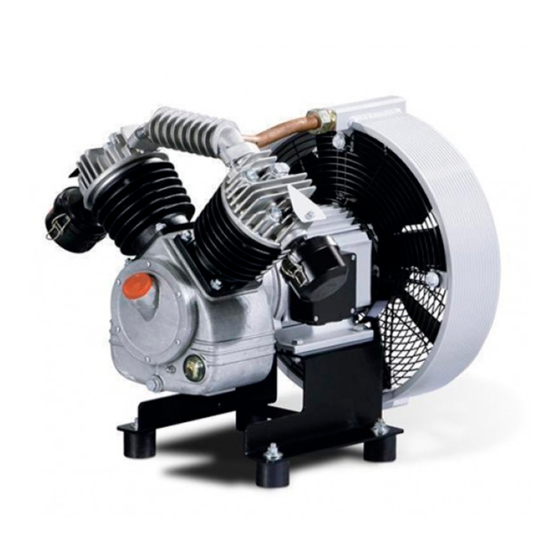
Fig. 2 Machine Overview
Options
Oil Level Monitoring
Silenced Air Filter
Air Filter with Plastic Casing
Fig. 3 Option C5: Oil Level Monitoring
Fig. 4 Option H9: Silenced Air Filter
Castors
Screwable Rubber Pads for Air Receiver Mounting
Fig. 5 Option H10: Air Filter with Plastic Casing
Fig. 6 Option H14: Castors
Fig. 7 Option H20: Screwable Rubber Pads
Screwable Rubber Pads
Operating Modes and Control Modes
Machine Operating Modes
External Control Unit
Fig. 8 Option H29: Screwable Rubber Pads
Safety Devices
Safety and Regulating Devices
Accessories
5 Installation and Operating Conditions
Ensuring Safety
Installation Conditions
Determining Location and Clearances
Ensuring the Machine Room Ventilation
Fig. 9 Recommended Machine Placement and Dimensions [MM]
Prevention of Thermal Problems
Operating the Machine in a Compressed Air Network
6 Installation
Ensuring Safety
Reporting Transport Damage
Fitting the Rubber Pads
Replacing the Air Filter
Fig. 10 Fitting the Rubber Pads
Fig. 11 Replacing the Air Filter
Connecting the Machine with the Compressed Air Network
Installing the Venting Valve
Fig. 12 Compressed Pipework
Installation Examples
Safety and Control Devices
Fig. 13 Install the Venting Valve On-Site
Fig. 14 Typical Installation of Safety and Regulating Devices
Two Machines with One Air Receiver
Connecting the Machine to the Power Supply
Fig. 15 Typical Installation of Two Machines with One Air Receiver
Options
Oil Level Monitoring
Fig. 16 Option C5: Oil Level Monitoring
Tab. 30 Option C5: Oil Level Monitoring Factory Setting
Fig. 17 Option C5: Changing the Oil Level Monitoring Setting
Mounting the Machine on an Air Receiver
Anchoring the Machine
Retrofitting the Sound Enclosure (Accessory)
Fig. 18 Option H20: Screwable Rubber Pads
Fig. 19 Option H29: Securing the Screwable Rubber Pads
Dismantling the Sound Enclosure
Fitting the Sound Enclosure
Fig. 20 Exchanging the Base Plate of the Compressor Block in an EPC 340-G
Fig. 21 Fitting the EPC 340 Sound Enclosure
Fig. 22 Replacing the Compressor Block's Base Plate and Modifying the Air Filter, EPC 440-G
Fig. 23 Fitting the EPC 440 Sound Enclosure
Fig. 24 Modifying the Air Filter, EPC 630-G / EPC 840-G
Fig. 25 Installing the Sound Enclosure, EPC 630-G / EPC 840-G
Fig. 26 Modifying the Air Filter, EPC 1100-G / EPC 1500-G
Fig. 27 Installing the Sound Enclosure, EPC 1100-G / EPC 1500-G
7 Initial Start-Up Ensuring Safety
Instructions to be Observed before Commissioning or Re-Commissioning
Checking Installation and Operating Conditions
Tab. 31 Re-Commissioning after Storage
Motor Protection
Motor Protection Setting by Direct Online Starting
Motor Protection Setting by Star-Delta Starting
Tab. 32 Check List of Installation Conditions
Checking the Direction of Rotation
Starting the Machine for the First Time
Measuring the Air Receiver Filling Time
Tab. 33 Air Receiver Filling Time
8 Operation
Switching on and off
Direct Start
Fig. 28 Switching the Compressed Air Station on and off
Direct Online Start with Solenoid Valve
Star-Delta Start
9 Fault Recognition and Rectification
Basic Instructions
Faults
Tab. 34 Faults and Remedies
10 1 Maintenance
Ensuring Safety
Following the Maintenance Plan
Logging Maintenance Work
Regular Maintenance Tasks
Compressor Oil Change Interval
Tab. 35 Regular Maintenance Tasks
Regular Service Tasks
Maintaining the Air Cooler or Fan Cowl
Tab. 36 Compressor Oil Change Intervals
Tab. 37 Regular Service Tasks
Cleaning the Air Cooler or Fan Cowl
Air Filter Maintenance
Fig. 29 Cleaning the Air Cooler or Fan Cowl
Air Filter (Sound Damping) Maintenance
Fig. 30 Air Filter Maintenance
Fig. 31 Option H9: Air Filter (Sound Damping) Maintenance
Air Filter (Plastic Housing) Maintenance
Fig. 32 Option H10: Air Filter (Plastic Housing) Maintenance
Drive Motor Maintenance
Checking the Oil Level
Topping up the Compressor Oil
Fig. 33 Checking the Oil Level
Changing the Compressor Oil
Fig. 34 Topping up the Compressor Oil
Check the Pressure Relief Valve
Pressure Relief Valves on the Cylinder Head, Collecting Pipe and Air Cooler
Fig. 35 Changing the Compressor Oil
Venting the Machine (De-Pressurising)
Fig. 36 Checking the Pressure Relief Valves on the Cylinder Head, Collecting Pipe and Air Cooler
Solenoid Valve Maintenance
Cleaning the Solenoid Valve
Fig. 37 Cleaning the Solenoid Valve
Replacing the Solenoid Valve
Cylinder Head and Valves
Checking Cylinder Head and Valves
Fig. 38 Replacing the Solenoid Valve
Cleaning the Cylinder Head and Valves
Starting the Machine and Performing a Trial Run
Tab. 38 Tightening Torque for Cylinder Head Screws
Documenting Maintenance and Service Work
Tab. 39 Logged Maintenance Tasks
11 Spares, Operating Materials, Service
Note the Nameplate
Ordering Consumable Parts and Operating Fluids/Materials
Fig. 39 Consumable Parts
Tab. 40 Consumable Parts
Kaeser Air Service
Replacement Parts for Service and Repair
12 1 Decommissioning, Storage and Transport
Commissioning
Packing
Storage
Transport
Safety
Transport with a Forklift Truck
Transport with a Crane
Fig. 40 Transporting with a Forklift Truck
Disposal
Fig. 41 Transporting with a Crane
13 Annex
Pipeline and Instrument Flow Diagram (P&I Diagram)
Dimensional Drawing
Advertisement
Quick Links
1
Compressor Oil Recommendation
Download this manual
Assembly and operating manual
1-stage piston compressor
EPC-G
No.: 9_5752 24 E
Manufacturer:
KAESER KOMPRESSOREN SE
96410 Coburg • PO Box 2143 • GERMANY • Tel. +49-(0)9561-6400 • Fax +49-(0)9561-640130
http://www.kaeser.com
Table of
Contents
Previous
Page
Next
Page
1
2
3
4
5
Advertisement
Table of Contents
Need help?
Do you have a question about the EPC-G Series and is the answer not in the manual?
Ask a question
Questions and answers
Related Manuals for KAESER EPC-G Series
Air Compressor KAESER EPC Series Service Manual
2-stage piston compressor (110 pages)
Air Compressor KAESER EPC1100-G Assembly And Operating Manual
1-stage piston compressor (102 pages)
Air Compressor KAESER ESD 442 SFC Technical Documentation Manual
(414 pages)
Air Compressor KAESER CSD series Service Manual
Screw compressor (134 pages)
Air Compressor KAESER SM 8 Service Manual
Screw compressor (83 pages)
Air Compressor KAESER AIRTOWER 3C Operator's Manual
Screw compressor (124 pages)
Air Compressor KAESER M26 Service Manual
Screw (208 pages)
Air Compressor KAESER SK 19 Service Manual
(85 pages)
Air Compressor KAESER SM 7.5 Operator's Manual
Screw compressor. sm tri-voltage, sigma control 2 (128 pages)
Air Compressor KAESER CSD 75 Service Manual
Screw compressor (81 pages)
Air Compressor KAESER Aircenter SX 3 Service Manual
Screw compressor, sigma control basic (156 pages)
Air Compressor KAESER M43 Service Manual
Screw compressor (246 pages)
Air Compressor KAESER M100 Operator's Manual
Screw compressor (384 pages)
Air Compressor KAESER M135 SIGMA CONTROL MOBIL Service Manual
Screw compressor (288 pages)
Air Compressor KAESER M43 Operator's Manual
Portable compressor (288 pages)
Air Compressor KAESER M122 Service Manual
Portable compressor (348 pages)
This manual is also suitable for:
Epc 340-g
Epc 440-g
Epc 630-g
Epc 840-g
Epc1100-g
Epc 1500-g
Table of Contents
Print
Rename the bookmark
Delete bookmark?
Delete from my manuals?
Login
Sign In
OR
Sign in with Facebook
Sign in with Google
Upload manual
Upload from disk
Upload from URL


Need help?
Do you have a question about the EPC-G Series and is the answer not in the manual?
Questions and answers