
Related Manuals for Unitech HT650


Summary of Contents for Unitech HT650
- Page 1 HT650 Rugged Handheld Terminal - HT650 - User’s Manual 400992G Version 0.2...
- Page 2 Handy Terminal User Guide...
-
Page 3: Table Of Contents
Table of Contents Charpt 1. References ..................1 1.1. General Use And Product Safety............1 1.2. Federal Communication Commission Interference Statement..3 1.3. SAR Compliance ................4 1.4. WEEE Compliance ................4 1.5. System Specifications............... 5 1.6. Environment Standard ..............7 1.7. - Page 4 Charpt 4. Communication................29 4.1. Bluetooth Device ................29 4.1.1. Connect to a Bluetooth Printer or GPS ........ 29 4.1.2. File transfer between two Terminals ........31 4.2. Wi-Fi Network ................. 32 4.3. Microsoft® ActiveSync® ..............33 4.4. Federal Communication Commission Interference Statement..33 Charpt 5.
-
Page 5: Charpt 1. References
Charpt 1. References Reserves the right to make improvements or changes in the products described in this document at any time without notices. While reasonable efforts have been made in the preparation of this document to assure its accuracy, assumes no liability resulting from any errors of omissions in this guide, or from the use of the information contained herein. - Page 6 Always make back-up copies of all important data. Easy done by using a cable or Single Cradle (sold by optional) to transfer data to the computer. Manufacturer is not liable for any data damages or data loss caused by deletion or corruption by using of this device, or due to the drained battery.
-
Page 7: Federal Communication Commission Interference Statement
1.2. Federal Communication Commission Interference Statement This device complies with Part 15 of the FCC Rules. Operation is subject to the following two conditions: (1) This device may not cause harmful interference, and (2) this device must accept any interference received, including interference that may cause undesired operation. -
Page 8: Sar Compliance
This transmitter must not be co-located or operating in conjunction with any other antenna or transmitter. 1.3. SAR Compliance This equipment has been SAR-evaluated for use in laptops (notebooks) with side slot configuration. Caution: Please also note that Terminal is limited in CH1~CH11 for 2.4GHz by specified firmware controlled in U.S.A. -
Page 9: System Specifications
1.5. System Specifications Processor Marvell PXA270 with 312 MHz 32 bits RISC Memory - 2GB Flash ROM - 64 MB SDRAM - Trans-missive Micro Reflective 2.4” TFT Display and Touch Panel 256K Color QVGA LCD with high brightness LED backlight - Resistive type touch panel (optional) buzzers Audio... - Page 10 Red: Charging Green: Fully charged - One two color LED scanner indicator Red: Scanning Green: Good scan Battery - Standard battery pack: 1100mAH, 3.7V, Li-Ion - Extended battery pack: 2000mAH, 3.7V, Li-Ion - One rechargeable 15mAH, 2.4V Li-MH backup battery - One battery cover sensor switch - Battery charge time: 1100mAH battery pack: 2.5 hours...
-
Page 11: Environment Standard
1.6. Environment Standard Storage Temperature -25℃ ~ 60℃ Operation Temperature -10℃ ~ 50℃ Humidity 95% non-condensing @ 40℃ Free Drop 1.2m (4ft) drop to concrete, 3 drops per 6 surfaces Tumble Drop 100 times 2 feet tumbles (200 drops) Environmental Sealing IP54 Standard +/-8KV Air Discharge, +/-4KV Contact Discharge... -
Page 13: Charpt 2. Introduction
Charpt 2. Introduction Congratulations on purchasing the Terminal, a Microsoft Windows® CE .Net rugged Terminal. It’s special combination of features make it perfect for using in a wide range of applications. These features as : Small rugged lightweight form factor Microsoft Windows®... -
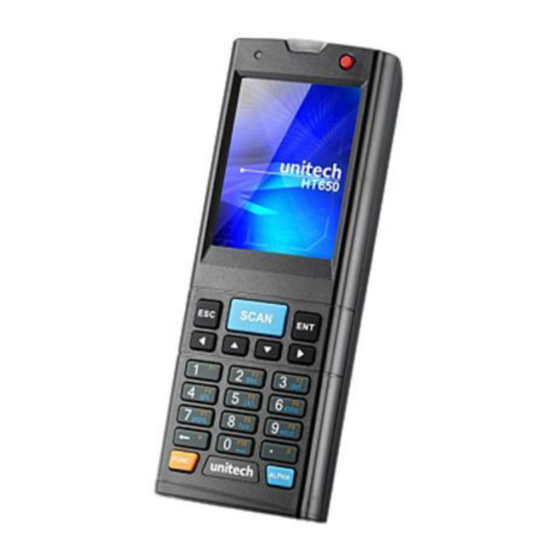
Page 14: General View
2.2. General View 2.2.1. Handy Terminal Front Side View Figure 2-1 2.2.2. Handy Terminal Back Side View Figure 2-2... - Page 15 Table 2-1 Description of Terminal General View 1 Scanner LED Indicator Scan is in progress “Red” color Scan is reading successful “Green” color 2 Charge LED “Red” color Battery Pack is still charging Indicator “Green” color Battery Pack is charged full 3 LCM/ Touch Panel Do specific action through touch panel by stylus 4 Scan key...
-
Page 16: Keypad Description
2.3. Keypad Description Figure 2-3 [SCAN] Scanning barcode [ENT] The Enter key confirms data entry. [FUNC] The Function Key is used in conjunction with specific number keys to operate as Hotkeys. [ESC] The escape key returns the user to a previous page. [Cursor] The cursor key moves the cursor around the screen. -
Page 17: The Soft Keypad
2.3.1. The Soft Keypad In applications that accept keypad input, the soft input panel (SIP) can be used to enter data using the stylus. The SIP is digital, QWERTY-Style keyboard ( See Figure 2-4 ). To open the SIP, tap the keyboard icon ( )... -
Page 18: Scanning Barcode
2.4. Scanning Barcode To use the scanning function, complete the following steps: Press the scan key. The scanner scans as long as you hold the key or for few seconds. Upon reading a barcode, the red LED indicator comes on until the trigger is release or few seconds. -
Page 19: Resetting The Handy Terminal
2.5. Resetting the Handy Terminal 2.5.1. Software (Warm) Reset A warm reset is a transition from the on, idle, or suspend power state that close all applications, clears the working RAM, but preserves the file system. Reason to Warm Reset:If an application “hangs”, initiate a warm reset to terminate the application only. -
Page 20: Saving To Flash
2.6. Saving to Flash The StorageCard folder let the application or a data file can be stored into the Flash Memory. To save an application or data to the Flash Memory, from your current application, select File Save As select the StorageCard location and save it. -
Page 21: Charpt 3. Getting Started
Charpt 3. Getting Started 3.1. Charging the Battery Pack Before using the Handy Terminal, perform the basic procedure of charging the battery pack through the following steps. 3.1.1. Installing the battery pack 1. Turn the switch cover latch and lift the battery cover away from the Handy Terminal. -
Page 22: Charging The Battery Pack With Power Adapter
2. Turn the switch cover latch and lift the battery cover away from the Handy Terminal. 3. Insert the battery pack into the battery compartment with the label facing out, and ensuring the battery snaps into place 4. Replace the battery cover by insert the top first, switch lock the battery cover latch to secure the cover to the Handy Terminal. -
Page 23: Charging The Battery Pack With Single Dock
3.1.3. Charging the battery pack with Single Dock a) Do not leave the battery pack inside of the Handy Terminal 1. Connect the Power cord to the Power adapter 2. Connect the power cord to a power source 3. Plug in the connector of the power adapter with Single Dock 4. -
Page 24: Starting The Handy Terminal
3.2. Starting the Handy Terminal Press the Power key to turn on/off the Handy Terminal. If the Handy Terminal does not power on, please perform a cold boot. See 2.5 Resetting the Handy Terminal on page 22 When a battery is fully inserted in Handy Terminal for the Caution:... -
Page 25: Navigating The Display
3.4. Navigating the Display 3.4.1. The Command Bar Use the Command bar at top of the screen to perform tasks in programs, such a opening a file, or editing a file. 3.4.2. The Task Bar The Task bar at the bottom of the screen displays the icon, an icon for the active program, the current time, and system icons for utilities loaded in memory. -
Page 26: Using The Stylus
3.4.3. Using the Stylus The stylus function like a mouse, hold the stylus like a pen or pencil. You can do action as follow. Double Tap:Touch the icon twice on the screen to open or execute Drag:Firmly press the icon on the screen to drag across the screen. -
Page 27: Control Panel
Figure 3-2 3.6.1. Barcode Setting The HT650 has an integrated laser scanner, which reads all major 1D barcode labels with excellent performance. NOTE: The reading software must be enabled in order to operate the scanner. - Page 28 To launch the Scanner Control Panel, follow these instructions: Tap Start → Settings → System Tap the Scanner icon. The Scanner Control Panel appears. NOTE: Or press Func key and “7” simultaneously to bring up the Scanner Control Panel screen. In the Scanner Control Panel screen, you can configure barcode scanner parameters such as enabling or disabling barcode symbologies, setting data transmission options, configuring magnetic and proximity reading options, and...
- Page 29 The HT650 provides an option for the barcode scanner, allowing you to scan and decode various types of 1D/2D barcodes. When it is necessary for the user to change the default barcode symbology for a different application, the Scanner Control Panel provides the ability to change default symbology, place delimiter characters behind scanned data, and save the settings.
- Page 30 Enable Char Check Transmit Barcode / Digit Check Others Disabl Symbology verification Char/digit Dutch (KIX) Post EAN 13 2 digit addenda, 5 digit addenda, Addenda required, Include addenda separator EAN 8 2 digit addenda, 5 digit addenda, Addenda required, Include addenda separator IATA 2 of 5 *data length...
-
Page 31: Backup And Restore Function
Barcode Symbologies 2D Char Check Transmit Enable Barcode Symbology / Digit Check Others Disable verification Char/digit Aztec Runes, *data length Codablock F *data length Code 49 *data length Data Matrix *data length EAN-UCC Composite YES UPC composite, *data length MaxiCode *data length MicroPDF417 *data length... - Page 32 If customer set enable “auto restore” item of Auto Restore on control panel. The system will execute restore procedure after cold reset. The Auto Restore function only accept the iBackup.bkp which is generated by Simple mode of Backup manager If you need more information please reference sunnysoft backup manager user manual.
-
Page 33: Charpt 4. Communication
Charpt 4. Communication 4.1. Bluetooth Device The system administrator has discovered and paired with a Bluetooth device from OBEX tools of Terminal. The system administrator can assign a friend name for Terminal that default friend name is “WindowsCE”. The OBEX tools is an application for Bluetooth manager of IT9000, That support FTP, Serial, Printer profile of Bluetooth. - Page 34 Figure 4-1...
-
Page 35: File Transfer Between Two Terminals
4.1.2. File transfer between two Terminals The role of one terminal must set as “server” from OBEX tools, and another must set as “client”. The role of server can be assigned a folder ( Ex “StorageCard” folder ) to share for client. The role of client can assign a file path to link the Server folder. -
Page 36: Wi-Fi Network
If connect ok between two Terminals , the Client will display the folder of server, you can create a folder , delete a folder , sent a file from client to server …. 4.2. Wi-Fi Network Terminal Wi-Fi 802.11 b/g model can communicate with the host computer using the on-board radio frequency component and Access point. -
Page 37: Microsoft® Activesync
The default admin password is “SUMMIT”. The on-board radio frequency component of Terminal has an utility, it is visible on the desktop, please tap the “Summit Client utility” icon. You can find more information about this applet for the radio configuration from http://www.summitdatacom.com/SCU.htm. - Page 38 Reorient or relocate the receiving antenna. Increase the separation between the equipment and receiver. Connect the equipment into an outlet on a circuit different from that to which the receiver is connected. Consult the dealer or an experienced radio/TV technician for help. FCC Caution: Any changes or modifications not expressly approved by the party responsible for compliance could void the user's authority to operate this equipment.
-
Page 39: Charpt 5. Appendix
Charpt 5. Appendix 5.1. AIM Code Identifiers of Symbol SE955 The follow information come from Symbol SE955 technical menu, if you need more information please reference Symbol SE955 technical menu: Each AIM Code identifier contains the three-character string ]cm where: ]= Flag Character(ASCII 93) c = Code Character ( See as follow) A: Code39... - Page 40 Standard data packet,No Function code 1 in first symbol position. Function code 1 in first symbol character position. Function code 1 in second symbol character postion. Example: A Code(EAN) 128 bar code with Function 1 character in the FNC1 first position, Aim Id is transmitted as ]C1 AimId.
- Page 41 Therefore, a UPC with two supplemental characters, 01234567890510, is transmitted to the host as a 21-character string, ]E00012345678905]E110.
Need help?
Do you have a question about the HT650 and is the answer not in the manual?
Questions and answers