Sign In
Upload
Manuals
Brands
Titan Logix Manuals
Measuring Instruments
TD80
Titan Logix TD80 Manuals
Manuals and User Guides for Titan Logix TD80. We have
3
Titan Logix TD80 manuals available for free PDF download: Product Manual, Application Note
Titan Logix TD80 Product Manual (162 pages)
Level Gauging and Overfill Prevention System
Brand:
Titan Logix
| Category:
Measuring Instruments
| Size: 8 MB
Table of Contents
Table of Contents
2
1 TD80 Introduction
5
About this Manual
5
Disclaimer
5
TD80 System Introduction and Description
6
About the TD80 System
6
TD80 System Components
6
Optional Components
7
Theory of Operation
7
The TD80 Alarm System
9
Overfill Prevention System Description
11
Table 1-1: Sequence of Events with Finch Relay Module Installed
13
Graphical Glossary of Terms
14
Figure 1-1: Dual Rod Probe Truck & Trailer Installation
14
Figure 1-2: Coaxial Probe Truck & Trailer Installation
15
Figure 1-3: SV Programming Kit
16
2 TD80 Installation
17
TD80 Installation Steps Overview
17
Pre-Installation Requirements
17
Installation Steps Overview
17
TD80 Installation Guidelines
19
TD80 Installation Test and Calibration
19
TD80 Basic Operation Tests
19
TD80 System Testing and Verification
19
Offset Calibration Methods
21
Figure 2-1: Sample Depth Chart
23
TD80 Probe and Transmitter Location
24
Locating the Probe
24
Figure 2-2: Locating the Probe
24
Locating the Transmitter
25
Figure 2-3: Trailer Mounted Tank
25
Mounting the Top Fitting
26
Figure 2-4: Locating the Top Fitting
26
Mounting the Anchor Cone
27
Figure 2-5: Locating the Anchor Cone
27
TD80 Mechanical Installation
28
Figure 2-6: Mechanical Installation of the TD80 System
28
Installation Procedure
29
Overview of the Installation Procedure
29
Figure 2-7: Dual Rod Probe Measurement
33
Figure 2-8: Cutting the Dual Rod Probe
34
Figure 2-9: Correct Probe Installation
35
Figure 2-10: Coaxial Probe Measurement
36
Figure 2-11: Cutting the Coaxial Probe
37
TD80 Basic System Installation Wiring
38
Finch 5332E/PS External Display, Red Terminal Board Wiring Instructions
38
Finch 5332E External Display, Green Terminal Board Wiring Instructions
38
Finch 5332, Internal Display Wiring Instructions
39
Figure 2-12: Basic System Wiring Diagram for Finch 5332E/PS External Display
40
Figure 2-13: Basic System Wiring Schematic for Finch 5332E/PS External Display
41
Figure 2-14: Basic System Wiring Diagram for Finch 5332E External Display
42
Figure 2-15: Basic System Wiring Schematic for Finch 5332E External Display
43
Figure 2-16: Basic System Wiring Diagram for Finch 5332 Internal Display
44
TD80 Basic Alarm Installation Wiring
45
Finch 5332E/PS, Red Terminal Board Wiring Instructions
45
Finch 5332E, Green Terminal Board Wiring Instructions
45
Figure 2-17: Basic Alarm Wiring Diagram for Finch 5332E/PS External Display
47
Figure 2-18: Basic Alarm Wiring Diagram for Finch 5332E External Display
48
TD80 Overfill Prevention System Installation Wiring
49
Finch Relay Module Installation Wiring
49
Figure 2-19: Overfill Prevention Installation Example
49
Figure 2-20: Finch Relay Module Internal Wiring Diagram
52
Figure 2-21: Finch Relay Module Overfill Prevention System Wiring Diagram for Finch 5332E/PS with Horns and Lights
53
Figure 2-22: Finch Relay Module Overfill Prevention System Wiring Schematic for Finch 5332E/PS with Horns and Lights
54
Figure 2-23: Finch Relay Module Overfill Prevention System Wiring Diagram for Finch 5332E with Horns and Lights
55
Figure 2-24: Finch Relay Module Overfill Prevention System Wiring Schematic for Finch 5332E with Horns and Lights
56
Figure 2-25: Basic Shutdown Wiring Diagram for Finch 5332E/PS External Display
57
Figure 2-26: Basic Shutdown Wiring Schematic for Finch 5332E/PS External Display
58
Figure 2-27: Basic Shutdown Wiring Diagram for Finch 5332E External Display
59
Figure 2-28: Basic Shutdown Wiring Schematic for Finch 5332E External
60
P2000 Overfill Prevention System
61
Figure 2-29: Single P2000 Overfill Prevention System Wiring Diagram
61
Figure 2-30: Single P2000 Overfill Prevention System Wiring Schematic
62
Figure 2-31: Dual P2000 Overfill Prevention System Wiring Diagram
63
Figure 2-32: Dual P2000 Overfill Prevention System Wiring Schematic
64
ABS Power Supply Wiring Example
65
Figure 2-33: ABS Power Supply Wiring Example Schematic
65
Finch Display Terminal and Jumper Locations
66
Figure 2-34: Finch 5332E External Display Terminal Board
66
Figure 2-35: Finch 5332E/PS External Display Terminal Board
67
Figure 2-36: Finch 5332 Internal Display Jumper Settings
68
Figure 2-37: Finch 5332E(/PS) External Display Jumper Settings
69
TD80 Installation Checklist
70
Table 2-1: TD80 Installation Checklist
70
3 TD80 and Overfill Prevention System Troubleshooting
71
Overview and General Techniques
71
TD80 System Specific Troubleshooting
72
Common System Wiring and Component Failures
73
Common Installation Wiring and Component Problems
84
Alternate TD80 System Troubleshooting
88
TD80 System Tests
88
Figure 3-1: Basic System Wiring Schematic for Finch 5332E/PS External Display
90
Figure 3-2: Basic System Wiring Schematic for Finch 5332E External Display
91
Figure 3-3: Basic System Wiring Diagram for Finch 5332 Internal Display
92
Figure 3-4: Single P2000 Overfill Prevention System Wiring Schematic
93
Figure 3-5: Finch Relay Module Overfill Prevention System Wiring Schematic for Finch 5332E with Horns and Lights
94
Figure 3-6: Basic Shutdown Wiring for Finch 5332E/PS External Display
95
Figure 3-7: Finch Relay Module Overfill Prevention System for Finch 5332E/PS with Horns and Lights
96
Figure 3-8: Basic Shutdown Wiring Schematic for Finch 5332E External Display
97
4 TD80 Technical Reference
98
Technical Specification Guide for Dual Rod Probes
98
Technical Specification Guide for Coaxial Probes
106
5 TD80 Operation
114
Figure 5-1: Dual Rod Probe Truck & Trailer Installation
114
Figure 5-2: Coaxial Probe Truck & Trailer Installation
115
Introduction to Operation
116
TD80 System Components
116
TD80 Operation
117
Modes of Operation
120
Alarm Disable Mode
120
Display Mode
120
Monitor Mode
120
Set Fill / Fall Mode
121
Alarms
121
Spill Alarm
121
Fill / Fall Alarm
122
High High Alarm
122
Fail Alarm
122
Disabling the 2 lo Message
122
Alarms Settings
123
Fill/Fall Alarm
123
HH Alarm
123
Spill/Fail Alarm
123
Figure 5-3: Coaxial Probe Alarm Settings
123
Figure 5-4: Dual Rob Probe Alarm Settings
123
Offset Calibration
124
Normal Operation Troubleshooting
125
Table 5-1: Normal Operation Troubleshooting
126
6 TD80 Programming
127
TD80 Transmitter and Probe Description
127
Programming the TD80
127
Birdfeeder 2 Programming Steps
128
Introduction
128
Programming Procedure
128
TD80 Birdfeeder 2 Detailed Programming Instructions
131
Graphical TD80 Programming Instructions Using Birdfeeder 2
133
Connecting the TD80 for Programming Using the SVRS232 to USB Converter
146
Figure 6-1: Connecting the TD80 for Programming in the Shop
146
Figure 6-2: Connecting the TD80 for Programming in the Shop Drawing
147
Figure 6-3: Connecting the TD80 for Programming on a Vehicle with a Finch 5332E Display (Green Board)
148
Figure 6-4: Connecting the TD80 for Programming on a Vehicle with a Finch 5332E Display (Green Board) Drawing
149
Figure 6-5: Connecting the TD80 for Programming on a Vehicle with a Finch 5332E/PS Display (Red Board)
150
Figure 6-6: Connecting the TD80 for Programming on a Vehicle with a Finch 5332E/PS Display (Red Board) Drawing
151
Advanced Birdfeeder 2 Programming Operations
152
Figure 6-7: MDU Text File Sample
153
Figure 6-8: Blank Depth Chart Form
159
MDU (Birdfeeder) Programming
160
Programming Checklist
162
Table 6-1: Programming Checklist
162
Advertisement
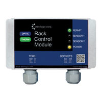
Titan Logix TD80 Product Manual (44 pages)
INTERFACE DEVICE FOR CONNECTING GAUGING SYSTEMS TO THERMISTOR AND OPTIC STYLE LOADING RACKS. Also available in an optic-only model
Brand:
Titan Logix
| Category:
Measuring Instruments
| Size: 2 MB
Table of Contents
Table of Contents
3
1 Introduction
4
About this Manual
4
Disclaimer
4
Introduction and Description
5
System Description
5
About the TD80 System
5
TD80 System Components
6
Optional Components
6
The TD80 Alarm System
7
Figure 1-1: Dual Rod Probe Truck & Trailer Installation
8
Graphical Glossary of Terms
8
Figure 1-2: Coaxial Probe Truck & Trailer Installation
9
2 Operation
10
Figure 2-1: Rack Control Module
10
Indicators
10
Table 2-1: LED Indicators
10
Sequence of Events
11
Table 2-2: Sequence of Events
12
3 Installation
13
Installation Steps
13
Pre-Installation Requirements
13
Table 3-1: Installation Steps
13
TD80 Installation Steps Overview
13
Figure 3-1: Wiring for Standard API Optic and Thermistor Sockets
15
Figure 3-2: Wiring for Standalone J560 7-Pin Optic Socket
16
Figure 3-3: Wiring for Optic API Socket and RCM -J560 Optic Socket
17
Figure 3-4: Wiring for Standard API Optic and Thermistor Sockets and RCM-J560 Optic Socket
18
Figure 3-5: TD80 and RCM Interconnection (no Junction Box), Single Installations, Wiring Schematic
19
Figure 3-6: TD80 and RCM Interconnection (no Junction Box), Single Installations, Wiring Diagram
20
Figure 3-7: TD80 and RCM Interconnection, Single Installation, Wiring Schematic
21
Figure 3-8: TD80 and RCM Interconnection, Single Installation, Wiring Diagram
22
Figure 3-9: TD80 and RCM Interconnection, Dual Installation (2X Single Displays), Wiring Schematic
23
Figure 3-10: TD80 and RCM Interconnection, Dual Installation (2X Single Displays), Wiring Diagram
24
Table 3-2: System Test and Verification Checklist
25
Figure 3-11: Sample Depth Chart
29
4 Troubleshooting
32
Overview and General Techniques
32
TD80 System Specific Troubleshooting
33
TD80 and RCM Intermittent Circuit Troubleshooting
41
5 Technical Reference
43
Figure 5-1: RCM Dimensions
43
Rack Control Module Kit Components
43
Specifications
43
Titan Logix TD80 Application Note (11 pages)
Retrofit Procedures
Brand:
Titan Logix
| Category:
Measuring Instruments
| Size: 0 MB
Table of Contents
Table of Contents
2
1 Customer Support
3
2 Returns for Repair, Replacement, or Credit
3
3 Introduction
4
Disclaimer
4
Safety
4
4 Pre-Installation
4
Required Materials
4
Initial Steps
5
5 Retrofit Procedures with Fluid in the Tank
6
Retrieve the TD80 Strap Table
6
Exchange the Transmitter
6
Transferring the TD80 Strap Table to the TD100
6
Performing Offset Calibration on the TD100
7
Confirming Offset Calibration on the TD100
7
6 Retrofit Procedures with Empty Tank
8
Retrieve the TD80 Strap Table
8
Exchanging the Transmitter
8
Transferring the TD80 Strap Table to the TD100
9
Performing Offset Calibration on the TD100
10
Installing the TD100
11
Confirming Level Readings of the TD100
11
7 Revision History
11
Advertisement
Advertisement
Related Products
Titan Logix TD100
Titan Logix TPM 053
Titan Logix FINCH II
Titan Logix MIC 10
Titan Logix Rack Control Module
Titan Logix Categories
Measuring Instruments
Gateway
Transmitter
Control Unit
Controller
More Titan Logix Manuals
Login
Sign In
OR
Sign in with Facebook
Sign in with Google
Upload manual
Upload from disk
Upload from URL