Sign In
Upload
Manuals
Brands
Titan Logix Manuals
Measuring Instruments
Rack Control Module
Titan Logix Rack Control Module Manuals
Manuals and User Guides for Titan Logix Rack Control Module. We have
1
Titan Logix Rack Control Module manual available for free PDF download: Product Manual
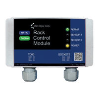
Titan Logix Rack Control Module Product Manual (44 pages)
INTERFACE DEVICE FOR CONNECTING GAUGING SYSTEMS TO THERMISTOR AND OPTIC STYLE LOADING RACKS. Also available in an optic-only model
Brand:
Titan Logix
| Category:
Measuring Instruments
| Size: 2 MB
Table of Contents
Table of Contents
3
1 Introduction
4
About this Manual
4
Disclaimer
4
Introduction and Description
5
System Description
5
About the TD80 System
5
TD80 System Components
6
Optional Components
6
The TD80 Alarm System
7
Figure 1-1: Dual Rod Probe Truck & Trailer Installation
8
Graphical Glossary of Terms
8
Figure 1-2: Coaxial Probe Truck & Trailer Installation
9
2 Operation
10
Figure 2-1: Rack Control Module
10
Indicators
10
Table 2-1: LED Indicators
10
Sequence of Events
11
Table 2-2: Sequence of Events
12
3 Installation
13
Installation Steps
13
Pre-Installation Requirements
13
Table 3-1: Installation Steps
13
TD80 Installation Steps Overview
13
Figure 3-1: Wiring for Standard API Optic and Thermistor Sockets
15
Figure 3-2: Wiring for Standalone J560 7-Pin Optic Socket
16
Figure 3-3: Wiring for Optic API Socket and RCM -J560 Optic Socket
17
Figure 3-4: Wiring for Standard API Optic and Thermistor Sockets and RCM-J560 Optic Socket
18
Figure 3-5: TD80 and RCM Interconnection (no Junction Box), Single Installations, Wiring Schematic
19
Figure 3-6: TD80 and RCM Interconnection (no Junction Box), Single Installations, Wiring Diagram
20
Figure 3-7: TD80 and RCM Interconnection, Single Installation, Wiring Schematic
21
Figure 3-8: TD80 and RCM Interconnection, Single Installation, Wiring Diagram
22
Figure 3-9: TD80 and RCM Interconnection, Dual Installation (2X Single Displays), Wiring Schematic
23
Figure 3-10: TD80 and RCM Interconnection, Dual Installation (2X Single Displays), Wiring Diagram
24
Table 3-2: System Test and Verification Checklist
25
Figure 3-11: Sample Depth Chart
29
4 Troubleshooting
32
Overview and General Techniques
32
TD80 System Specific Troubleshooting
33
TD80 and RCM Intermittent Circuit Troubleshooting
41
5 Technical Reference
43
Figure 5-1: RCM Dimensions
43
Rack Control Module Kit Components
43
Specifications
43
Advertisement
Advertisement
Related Products
Titan Logix FINCH II
Titan Logix MIC 10
Titan Logix TD100
Titan Logix TD80
Titan Logix Categories
Measuring Instruments
Transmitter
Gateway
Monitor
Control Unit
More Titan Logix Manuals
Login
Sign In
OR
Sign in with Facebook
Sign in with Google
Upload manual
Upload from disk
Upload from URL