Table of Contents
Advertisement
Odin II TTL Flash Trigger for Canon
Thank you for purchasing a Phottix product
Note: Before using the Odin II TTL Flash Trigger for Canon, please read this
instruction manual carefully.
Odin II TTL Flash Trigger is a new generation of TTL triggering system based on the
previous Odin TTL Flash Trigger. While keeping the Odin system's core functions
such as of wireless power level adjustment, zoom adjustment and etc, the new system
has been added with a series of innovative functions to extend its utility and stability,
including group/channel/ID settings, AF assist light, wireless modeling light
brightness control. A whole new structural design allows for easier and faster to
operation.
Many TTL flashes have been tested but the manufacturer cannot guarantee that all
third party TTL flashes will function properly with the Phottix Odin II. It is designed
and optimized for Canon Flashes using the ETTL II/ETTL system.
Please Note:
1. After turning on the Phottix Odin II transmitter and receivers, slave mode does
not need to be set on flashes on Photix Odin II receivers, but flashes need to be set
in ETTL mode.
2. Ensure there is a good hot shoe connection between the transmitter and camera,
flashes and receivers for best performance.
3. Many TTL flashes have been tested but the manufacture cannot guarantee that all
third party TTL flashes will function properly with the Phottix Odin II. It has been
designed and optimized for original canon flashes using the ETTL II/ETTL system.
4. Turn of all devices-flashes/strobes, camera, and the Phottix Odin II transmitter
and receivers when connecting and disconnecting the devices.
FCC Interference Statement:
This device complies with part 15 of the FCC Rules. Operation is subject to the
following two conditions: (1) This device may not cause harmful interference, and (2)
this device must accept any interference received, including interference that may
cause undesired operation.
FCC Radiation Exposure Statement:
This equipment complies with FCC RF radiation exposure limits set forth for an
uncontrolled environment. This device and its antenna must not be co-located or
Advertisement
Table of Contents

Subscribe to Our Youtube Channel
Related Manuals for Phottix Odin II TTL


Summary of Contents for Phottix Odin II TTL
- Page 1 Note: Before using the Odin II TTL Flash Trigger for Canon, please read this instruction manual carefully. Odin II TTL Flash Trigger is a new generation of TTL triggering system based on the previous Odin TTL Flash Trigger. While keeping the Odin system’s core functions...
- Page 2 operating in conjunction with any other antenna or transmitter. NOTE: This equipment has been tested and found to comply with the limits for a Class B digital device, pursuant to Part 15 of the FCC Rules. These limits are designed to provide reasonable protection against harmful interference in a residential installation.
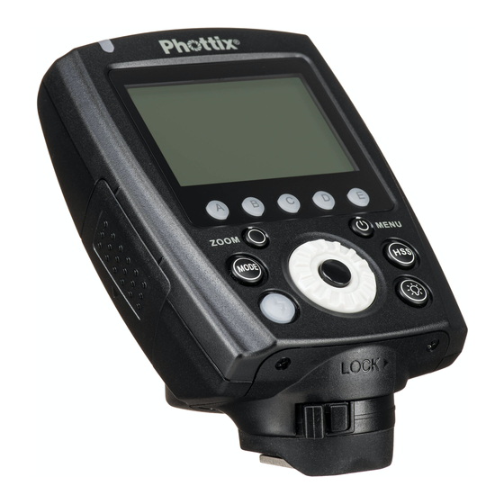
- Page 3 VI. Technical Specifications VII. Warnings I. Parts Transmitter 1. LED Indicator 2. LCD Screen 3. Zoom Button 4. Mode Button 5.Test Button/Flash Exposure Confirmation Lamp 6.< >:Select/Set Button 7.Locking Ring 8.Group Button(From right to left are A, B, C, D, E consecutively) 9.Power Button/Menu Button 10.
- Page 4 II. Preparation Before Use Installing the Batteries 1. Press the battery compartment cover on Phottix Odin II transmitter and receiver, slide it down as directed to open the battery cover. 2. Insert the batteries. Make sure the “+” and“-”battery contacts are correctly oriented as shown.
- Page 5 2. Turn off: Press and hold the power button until the LCD screen goes blank. Firing Group, Channel and ID Setting 1. The Phottix Odin II system has up to 5 groups: A, B, C, D, E, 32 channels and settable IDs from 0000 to 9999.
- Page 6 E will not be displayed on the screen, nor can the IDs be settable. Upgrading firmware by USB The firmware of the transmitter and receivers can be upgraded using the included USB cable. Any upgrades and full instructions will be announced on the Phottix blog (journal.phottix.com). III. LCD Display...
- Page 7 Ratio Functions Screen Receiver...
- Page 8 IV. Functions and Operations To Set the Working Mode TTL/M Mixed Functions Screen allows you to set to TTL, Manual and OFF for A/B/C/D/E independently, along with the EV and Power Level for each group. The Ratio Functions Screen is similar to a original Canon TTL system. You can set the flash ratio for group A and B from 8:1 to 1:8, and the EV as well.
- Page 9 Modeling Light Button Pressing the modeling light button on the transmitter will allow you to adjust the modeling light brightness (0-9 grades) of Phottix Indra studio light series: Press button to display the screen for modeling light brightness adjustment; press the group button to choose the group to set;...
- Page 10 To Adjust the Flash Zoom Phottix Odin II allows the zoom level of flashes to be set wirelessly as Auto or Manual: Auto Zoom: Flash zoom setting will change dynamically as a camera zoom ring is adjusted.
- Page 11 High Speed Continuous Shooting Using the Phottix Odin II will result in slower continuous high speed shooting than can be achieved when using a flash directly on the camera. There are differences in metering between the Phottix Odin system related to groups and the pre-flashes than Canon’s native system.
- Page 12 Compatibility with Phottix Flashes/Strobes/Flash Triggers Support Master Unit Slave Units TTL&M Info Transmission? Phottix Odin TTL Receiver for Canon Phottix Strato Receiver for Canon Phottix Strato II Multi Receiver for Canon Phottix Mitros+ Transceiver Flash for Canon ODIN RX Mode...
- Page 13 2. Turn to select an item to set and press button. 3. Turn to select the setting and press to confirm the setting. 4. Press to exit the custom function setting screen. Custom Functions Chart Custom Setting and Function Functions Setting No.
- Page 14 Reset all the settings RESET on transmitter VI.Technical Specification 2.4 GHz Frequency 100m+ Distance 32channels Channels 5 groups– A, B, C,D,E Groups 2X AA type alkaline batteries or NI-MH batteries(TX Power Supply and RX), 5V DC on receiver(external power port) 1/8000 sec* Max sync speed Standby Current≤30mA;...
- Page 15 2. Please shut down the power of all devices when installing the wireless trigger. 3. Do not drop or crush. 4. Do not use the wireless trigger at flammable, explosive or high temperature environment. 5. Do not use harsh chemicals or solvents to clean the body. Use a soft cloth or lens paper.
Need help?
Do you have a question about the Odin II TTL and is the answer not in the manual?
Questions and answers