Table of Contents
Advertisement
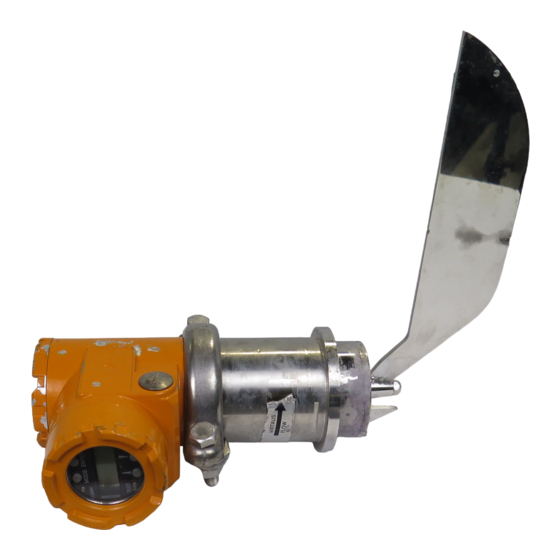
SMART-PULP
Operating and Installation Instructions
WARNING!
Before disconnecting or installing the
transmitter, ensure that the process pipe is
empty and depressurized. Observe the safety
instructions specified for the process.
HART® is a registered trademark of HART Communication Foundation.
Smart Consistency Transmitter
Contents:
We reserve the right for technical changes without prior notice.
Valmet Automation Inc., Measurements
PO Box 237, FIN-33101 Tampere, Finland
Tel +358 3 2668 111, Telefax +358 3 2668 448
BCs160VA
Nov. 15, 1997
Advertisement
Table of Contents

Related Manuals for Valmet SMART-PULP

Summary of Contents for Valmet SMART-PULP
-
Page 1: Table Of Contents
1.2 Electrical connections 1.3 Setting up the transmitter 2 TRANSMITTER FUNCTIONS (MENUS) 2.1 MEASUREMENT 2.2 CONFIGURATION 2.3 CALIBRATION 2.4 Sample taking and processing 3 SMART-PULP’S OPERATION AND CONSTRUCTION 3.1 Construction 3.2 HART® communications 4 MAINTENANCE AND DIAGNOSTICS 4.1 Troubleshooting 4.2 Error messages 4.3 Checking the operation of force measurement... -
Page 2: Putting Into Operation
BCs160VA SMART-PULP Smart Consistency Transmitter Nov. 15, 1997 1 PUTTING INTO OPERATION WARNING ! Before installing the process coupling, make sure that the process line is empty and depressurized ! 1.1 MECHANICAL INSTALLATION 1.1.1 Points of importance in installation • The transmitter must be mounted at 90 angle to •... - Page 3 Valve and pump axes Section E-E parallel Figure 1.1.2a Preferred mounting locations for SMART-PULP in pipework 1.1.2 Selecting the mounting location requires careful consideration, because a substantial buildup of air in the pipe may affect the Preferred mounting locations: 1. A, 2. B1, 3. B2 measurement accuracy.
- Page 4 NOTE! Due to the risk of plugging, this installation is not suitable for unscreened pulp. High consistencies (SMART-PULP HL) SMART-PULP HL, the transmitter for high consistencies, is installed on the small-diameter pipe section following the stock pump. This will ensure sufficient flow velocity.
- Page 5 SMART-PULP Smart Consistency Transmitter Nov. 15, 1997 <2 %Cs: DN25 pipe <3 %Cs: DN32 pipe >3 %Cs: DN40 pipe DN100 Option 1.699 STE AM POWER min. 1000 min. 1500 FLOW Figure 1.1.2e Low-consistency measurement with bypass line (SMART-PULP UL) ςς5...
- Page 6 (e.g. when stopping or starting the process). The deflectors Figure 1.1.3a Installation of SMART-PULP LL/LS/GL/RL/HL must be centered exactly in line with the process coupling. The deflectors have Ø5 mm holes to facilitate installation; for instance, you may insert a piece of wire through the holes.
- Page 7 Regulations concerning pressurized vessel installations must be observed when welding the coupling. p max. T max. FLOW *) Plate thickness 4 mm **) Plate thickness 8 mm Figure 1.1.3c Installation for SMART-PULP WS Figure 1.1.3b Reinforcing the process coupling...
- Page 8 Figure 1.1.3f Process coupling welding guide FLOW *) Plate thickness 4 mm Figure 1.1.3d Installation of SMART-PULP HL in digester blow line Lamination Figure 1.1.3e Installation for SMART-PULP JL Installing the transmitter Place PTFE gasket in the groove on the transmitter’s coupling flange (Fig.
-
Page 9: Electrical Connections
Washer 1 Signal Wires Washer 2 Shield grounding wire Figure 1.2.1a SMART-PULP’s wiring connections Figure 1.2.1b SMART-PULP end of the connection (2-W). The connections are the same when cable wiring for remote operator terminal. remote operator terminal is in use. - Page 10 BCs160VA SMART-PULP Smart Consistency Transmitter Nov. 15, 1997 SMART-PULP end of the connection cable wiring for remote operator terminal, if the remote operator terminal is used. 8 7 6 5 1 2 3 4 Transmitter housing SMART-PULP's operator terminal wiring connections, remote or local.
-
Page 11: Setting Up The Transmitter
(i.e., not a standby transmitter installed to replace Figure 1.3a SMART-PULP’s operator unit e.g. a faulty transmitter). This procedure enables an already The operator unit consists of four pusbutton keys and an calibrated consistency measurement. - Page 12 BCs160VA SMART-PULP Smart Consistency Transmitter Nov. 15, 1997 value, which you can change with the arrow keys. Even if there is filler, you may accept 0.00% as filler Pressing [ENTER] will save the new value. If you do content, provided that you do not want to change the...
- Page 13 ENTER between laboratory and See the NOTE on the page 12. SAVE OK? transmitter output. ENTER BLADE TY ———————————————— Back to main menu. CONFIGUR Table 1.3a SMART-PULP Start-up calibration and configuration: menu texts and keystrokes.
- Page 14 Then use the arrow keys to get the correct recipe number, i.e., the same on which the samples were SMART-PULP. Use the arrow keys to change the taken and which you want to calibrate. The displayed reading in accordance with the laboratory result, and default number should be correct unless the recipe press [ENTER] to accept the value.
- Page 15 MEASURE menu by pressing [ESC] [ESC] This will make the transmitter’s operation consistent [ENTER]. with other corresponding SMART-PULP transmitters. Consistent force measurement enables the new CALIBRATION WITHOUT SAMPLING transmitter to be calibrated so that it will operate...
- Page 16 SMART-PULP instruction set (275 user interface without SMART-PULP instruction set: refer to the Calibration chapter.) When the 275 user interface with SMART-PULP programming facility is connected to SMART- PULP’s supply lines, it displays the following menu: SMARTPULP:tag Online...
- Page 17 BCs160VA SMART-PULP Smart Consistency Transmitter Nov. 15, 1997 To change an item, select the desired line with the Pressing the RIGHT arrow key on the menu’s cursor and then press the RIGHT arrow key. Press second line will display the alarm current in the LEFT arrow or ENTER to exit the menu.
- Page 18 BCs160VA SMART-PULP Smart Consistency Transmitter Nov. 15, 1997 Pressing the RIGHT arrow key at 2 Sampling opens Two-point calibration (Use both) changes both P1 the following two options: slope and P2 offset parameters, so that new calibration curve goes through both laboratory 1 Start sample 1 points.
- Page 19 BCs160VA SMART-PULP Smart Consistency Transmitter Nov. 15, 1997 275 software tree Calibration with 275 HART® user interface with SMART-PULP instruction set (SMARTPULP DLL) Low Rnge PV %Cs Upp Rnge Active recipe Sensor tmp. Process tmp. Min. span Housing tmp. AO mA Damping Shear F.
-
Page 20: Transmitter Functions (Menus)
Nov. 15, 1997 2 TRANSMITTER FUNCTIONS (MENUS) Operations and calibration from SMART-PULP’s own operator keys You can always get to the main menu by pressing ESC a sufficient number of times. You can select the following main functions with arrow keys from the main menu: 1. -
Page 21: Measurement
Nov. 15, 1997 2.1 MEASUREMENT Shear force measurement will immediately be on SMART-PULP does not measure ash, i.e. fillers. when you first power up the transmitter. The output However, the transmitter is usually calibrated to for uncalibrated measurement is shown in per indicate total consistency. - Page 22 Upper range-value in % Cs. Warning of exceeding the recommended upper limit: refer to above text. If span is too wide (> 30 N), SMART-PULP will not accept the upper limit. In that case you have to lower the upper limit and/or raise the lower limit.
-
Page 23: Calibration
General description Figure 2.3a shows the calibration principle. Calibration curves for several applicable pulp types are saved in SMART-PULP’s memory for each sensor type. The calibration curves, experimentally defined in Valmet Automation’s laboratory, represent consistency (% Cs) as a function of the shear force (N) acting on the sensor. - Page 24 NOTE! The pulp type to be calibrated must be transmitters, including the P1 and P2 values active, i.e. in measurement, when you do the calculated by SMART-PULP after execution of the calibration. The active recipe number must be the LABORATO menu. For example, when a faulty same in the MEASURE and CALIBRAT menus.
- Page 25 SMART-PULP helps you in sample taking by NOTE! Mechanical pulps are softwood pulps. calculating the consistency’s average value and standard deviation for the sampling period.
- Page 26 SMART-PULP will issue a warning If required, repeat the procedure for one or both against calibrating at less than 25% consistency samples.
- Page 27 BCs160VA SMART-PULP Smart Consistency Transmitter Nov. 15, 1997 calibration or if a new special sensor blade is used press arrow key to go to the previous options. If the with an older transmitter, the SPecial GRADE menu difference between the two samples is less than 25%...
-
Page 28: Sample Taking And Processing
1. Representative point in pipe sample. Keeping the several samples separate from the very You should observe the sampler’s (e.g. Valmet beginning will allow you to determine the time- NOVE) installation instructions when choosing the related representativeness and efficiency of mounting location for the sampler. -
Page 29: Smart-Pulp's Operation And Construction
Nov. 15, 1997 3 SMART-PULP’S OPERATION AND CONSTRUCTION SMART-PULP uses a piezoresistive force transducer to measure the shear force acting on its sensor blade. The shear force is proportional to pulp consistency. Oil damping prevents the effects of pipework vibration on the measurement. - Page 30 BCs160VA SMART-PULP Smart Consistency Transmitter Nov. 15, 1997 Figure 3.1a SMART-PULP Mechanical construction...
- Page 31 BCs160VA SMART-PULP Smart Consistency Transmitter Nov. 15, 1997 Figure 3.1b SMART-PULP Electronics...
-
Page 32: Hart® Communications
MAINTENANCE AND DIAGNOSTICS Troubleshooting SMART-PULP does not find all faults by itself. The user’s actions are required in such cases. The The transmitter monitors its own operation necessary actions are defined in connection with the continuously. Any detected faults are indicated in error messages. -
Page 33: Error Messages
Select MESSAGES in the DIAGNOST menu, first current output error message will be displayed. Press [ENTER]. Since SMART-PULP displays and communicates The transmitter displays the ERASE? prompt. Press the shear force and mA output in digital format, the [ENTER] to remove the selected message. Proceed... -
Page 34: Adjusting The Position Of The Display Unit
Replacing the sensor blade NOTE! Stable reading before usng the arrow keys. Procedure: In both cases SMART-PULP finally asks SAVE • The sensor blade’s retaining nut is secured with OK?. Press [ENTER] if you want to save the results. Loctite. The nut can be unscrewed without heating. -
Page 35: Parts List
2-W/3-W, and the number and name of the required part. Example: BCs160VA, Nov. 15. 1997, SMART-PULP, RL/SS, M1 No. 960720690, 2-W, 116 RL sensor (serial number is constructed as follows: 96 = year, 07 = week, 20690 = ordinal number). - Page 36 BCs160VA SMART-PULP Smart Consistency Transmitter Nov. 15, 1997 MO D E EN TER C O M M C O M M TE S T+ TE S T- 131 103 82 103 Figure 5 SMART-PULP Parts list...
-
Page 37: Technical Specifications
Weights Damping set at factory: 20 s for HL and 2 s for other sensors. • SMART-PULP WS with local operator unit: 6.2 kg • SMART-PULP WS with remote operator unit: 7.4 kg Permissible velocity of flow (m/s): • Other SMART-PULP types with local operator min/max unit: 4.8 kg... - Page 38 AISI316L (blow line installation, only HL sensor) Output signal 2-wire system: 4-20 mA + HART® Display and operator unit SMART-PULP with remote operator unit SMART-PULP with local operator unit Process coupling and its material No process coupling Standard, AISI316L (LL,LS,UL,GL,RL,HL)
- Page 39 C O M M TE S T - TE S T + Sensor Dimension H (from edge of coupling) SMART-PULP’s remote operator terminal. Length of connecting cable: 9.75 m. 95 Standard coupling 57 Plastic-pipe coupling 60 Standard coupling 38 Blow line coupling...
-
Page 40: Applications
When choosing a sensor for a particular application we specify a “window” whose The PULPSEL PC program supplied by Valmet Automation width represents the process’s flow velocity can also be used to select the best sensor. PULPSEL also range (e.g. 1.2 to 3 m/s) and whose height calculates and prints the required minimum lengths of represents the consistency range (e.g. - Page 41 For pulp E (and L) (1)+(2): For pulps A, B, F, G and L For pulp K (1): For pulps C, D and J SMART-PULP UL (1): For pulp G )+(2): For pulps A and B For pulps F and G...
- Page 42 (1)+(2)+(3): For pulp J (1): For pulps E and F (1)+(3)+(4): For pulp K (1)+(2): For pulp L SMART-PULP RL For pulps H and I (1)+(2): For pulps A and B (1)+(2): For pulps C, D, E (1): For pulp G...
- Page 43 Smart Consistency Transmitter Nov. 15, 1997 (1)+(2): For pulps A and B (1): For pulps C and D SMART-PULP JL (1): For pulps C, D, E and K (1)+(2): For pulps L, J and F (1)+(2)+(3): For pulps A, B and G (4) Also suitable for this zone when flow velocity variation is max.
-
Page 44: Materials For Wetted Parts
NETHERLANDS; Valmet Automation B.V., PO Box 775, 3700 AT Zeist, The Netherlands, Tel. +31 30 6956500, Telefax +31 30 6953951, NORTH AMERICA; Valmet Automation (USA) Inc., 30 Thomas Drive, Westbrook, ME 04092, USA, Tel. + 1 207 774 4461, Telefax + 1 207 774 1065, SINGAPORE; Valmet (SEA) Pte Ltd./Automation Division, 152 Beach Road, # 24-05/08 Gateway East, Singapore 189721, Republic of Singapore, Tel.
Need help?
Do you have a question about the SMART-PULP and is the answer not in the manual?
Questions and answers
Hallo, wer ist in Deutschland der Ansprechpartner für Smart-Pulp-Dichtemessungen?
Is it require sealing water line for yokogawa consistensy transmeter