
Related Manuals for Valmet Valmet MCA

Summary of Contents for Valmet Valmet MCA
- Page 1 Valmet Microwave Consistency Transmitter – Valmet MCA Installation & Owner’s manual OUL00298 V2.3 EN...
-
Page 3: Table Of Contents
3.6. Transmitter Central Unit (TCU) and shield..20 10.2. Process Conditions........41 3.7. Electrical Connections ........20 10.3. Self-diagnostics error messages....43 3.8. Valmet MCA-F Sensor Deflector Plate Installation Replacing Components Guide..............22 11.1. Sensor Electronics.........45 Setting Up 11.2. Antenna cables, Fork Sensor......46 4.1. Mechanical Inspection........23 11.3. - Page 4 Valmet Mircowave Consistency Transmitter Installation & Owner’s manual OUL00298 V2.3 EN...
-
Page 5: Caution / Warning
The applicable electrical safety regulations must be closely followed in all installation work! Before any welding works in the vicinity of the devices, make sure that operating voltage is not connected! Valmet Mircowave Consistency Transmitter Installation & Owner’s manual OUL00298 V2.3 EN... -
Page 6: Recycling And Disposal
A materials list is delivered with the device. Upon request, the manufac- turer will provide more detailed instructions for recycling and disposal. Used devices may also be returned to the manufacturer for recycling and disposal against a separate fee. Valmet Mircowave Consistency Transmitter Installation & Owner’s manual OUL00298 V2.3 EN... -
Page 7: Introduction
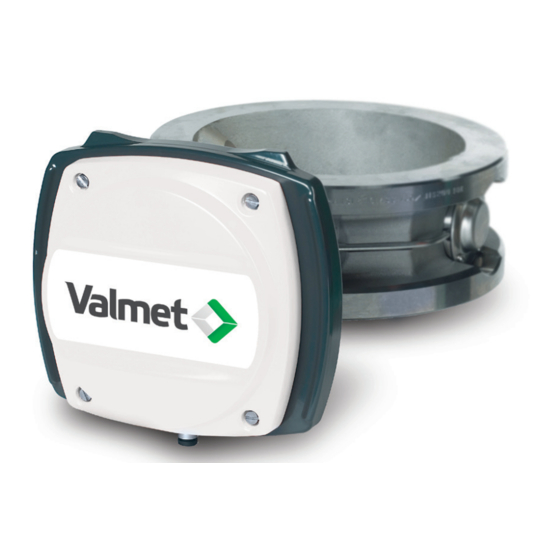
Fig. 2. Valmet MCA-F. pulp type-independence, insensitivity to flow speed, and single-point calibration. There are two different models of Valmet MCA sensors: - Valmet MCA-F Fork sensor (figure 2). - Valmet MCA-FT Flow-through sensors (figure 3). Valmet MCA also includes a user interface known as Transmitter Central Unit (TCU) (figure 1). - Page 8 Notes Valmet Mircowave Consistency Transmitter Installation & Owner’s manual OUL00298 V2.3 EN...
-
Page 9: Structure
2. Structure Valmet MCA comprises the sensor unit and a user in- 2.2. MCA-FT terface called Transmitter Central Unit. There are two The body of the Flow-Through sensor is a pipe, which, sensor models: MCA-F Fork Sensor and MCA-FT Flow-... - Page 10 Fig. 3. Valmet MCA-F construction drawing: 1. Microwave Antenna, 2. Sensor Head, 3. Pt-100 Thermoelement, 4. Antenna Cables, 5. Sensor Body, 6. Antenna Sealing, 7. Fixing Clamp, 8. Base Plate Assembly, 9. Sensor Electronics, 10. Sensor Cover. Valmet Mircowave Consistency Transmitter...
- Page 11 Fig. 4. Valmet MCA-FT construction drawing: 1. Sensor Cover, 2. Sensor Electronics, 3. Base Plate Assembly, 4. Pt-100 Thermoelement, 5. Sensor Body, 6. Antenna Sealing, 7. Microwave Antenna, 8. Antenna Flange, 9. Antenna Cable, 10. Antenna Cover. Valmet Mircowave Consistency Transmitter...
-
Page 12: Sensor Electronics
2.3. Sensor Electronics 2.4. Transmitter Central Unit (TCU) Sensor electronics is the same for both Fork and TCU is Valmet MCA's user interface and calculator. Flowthrough sensors. Refer to figure 6. The sensor Perform operations using the number buttons and other electronics card is installed between the round cover buttons and the four-line display. -
Page 13: Installation
– After the sensor there should be a straight section of pipe, length at least 2 times the pipe diameter, before a change in pipe profile. – Adjacent to Valmet MCA-F sensor or one meter be- fore it there must not be objects inserted into the pipe. - Page 14 Fig. 1. Valmet MCA-F Installation on a vertical pipe: A. after a pump, B. after a horizontal pipe. Fig. 2. Valmet MCA-F Installation on a horizontal pipe: A. after a vertical pipe, B. after a bend in the pipe. Valmet Mircowave Consistency Transmitter...
- Page 15 Fig. 3. Valmet MCA-FT Installation on a vertical pipe: A. after a pump, B. after a horizontal pipe. Fig. 4. Valmet MCA-FT Installation on a horizontal pipe: A. after a bend in the pipe, B. after a vertical pipe. Valmet Mircowave Consistency Transmitter...
- Page 16 Fig. 6. Valmet MCA-FT installation directly after a pump. Fig. 5. Valmet MCA-FT installation directly after a pump. Valmet Mircowave Consistency Transmitter Installation & Owner’s manual OUL00298 V2.3 EN...
-
Page 17: Sensor Dimensions
3.3. Sensor dimensions 275 (10.8”) 156 (6.1”) Fig. 7. Dimensions, Valmet MCA-F. MCA FT50/2" MCA FT100/4” 254 (10”) 226 (8.8”) Fig. 8. Dimensions, Valmet MCA-FT50 and -FT100. Valmet Mircowave Consistency Transmitter Installation & Owner’s manual OUL00298 V2.3 EN... - Page 18 MCA FT150/6" MCA FT200/8" 304 (12”) 280 (11”) Fig. 9. Dimensions, Valmet MCA-FT150 and -FT200. MCA FT300/12" MCA FT250/10" 330 (12.9”) 355 (14”) Fig. 10. Dimensions, Valmet MCA-FT250 and -FT300. Valmet Mircowave Consistency Transmitter Installation & Owner’s manual OUL00298 V2.3 EN...
-
Page 19: Mounting Dimensions
Valmet MCA-F Installing the process coupling: – Make a 71 mm hole in the flow pipe in line with the The fork-type Valmet MCA-F sensor is installed in a sensor. process coupling welded onto the side of the process – If necessary, shape the process coupling (curvature... -
Page 20: Transmitter Central Unit (Tcu) And Shield
NOTE: Do not place the sensor cable on cable shelves that contain cables of motors, pumps or other electrical cables. 232 (9.13") 133 (5.24") 31 (1.22") 70 (2.76") Fig. 15. TCU shield mounting dimensions. Valmet Mircowave Consistency Transmitter Installation & Owner’s manual OUL00298 V2.3 EN... - Page 21 1000 or CS2+. – Connect the current output line to connector CSIN or CSIN2. NOTE: Valmet MCA's current supply is passive and needs an external source of current. The minimum supply voltage is dependent on resistance. Operating region Fig. 16. TCU's Current output load capacity.
-
Page 22: Valmet Mca-F Sensor Deflector Plate Installation Guide
(see Technical specific- – Tighten the mounting clamp screws. ations). Align with the sensor Fig. 18. Valmet MCA-F Sensor deflector plate installation guide, A. Saddle, B. Deflector plate. Valmet Mircowave Consistency Transmitter Installation & Owner’s manual OUL00298 V2.3 EN... -
Page 23: Setting Up
Scale the current output according to Chapter 6.2. Calibrate the consistency according to Chapters 7.1 and 7.2. After you have completed these procedures, Valmet MCA is ready to measure consistency. Valmet Mircowave Consistency Transmitter Installation & Owner’s manual OUL00298 V2.3 EN... - Page 24 Notes Valmet Mircowave Consistency Transmitter Installation & Owner’s manual OUL00298 V2.3 EN...
-
Page 25: User Interface And Operation
5. User Interface and Operation 5.1. Transmitter Central Unit Forward arrow: Use the forward arrow in Edit mode The operation unit of Valmet MCA is the Transmitter to move to the next character. Central Unit (TCU). Down arrow: Use the down arrow to scroll down if Number buttons: Use number keys to enter numerical there are more than four lines. -
Page 26: Operations Menu
Sample history Output signal 1 Output signal 2 User settings Device info Set clock Address Error log Diag.values Diag.alarms Chemical compensation Temperature compensation Sensitivity correction Recipes Fig. 2. Operations Menu Valmet Mircowave Consistency Transmitter Installation & Owner’s manual OUL00298 V2.3 EN... -
Page 27: Configuration
Use the up arrow and down arrow buttons to make your selection. If you Select ON, program make measure- ment signal level adjustment automatically when it goes too low. Valmet Mircowave Consistency Transmitter Installation & Owner’s manual OUL00298 V2.3 EN... -
Page 28: Device Information
H W V e r : 0 0 0 1 S W V e r : 0 0 0 1 6.6. Address Valmet MCA's address on HART bus. S/N: Sensor electronics serial number. HW Ver: Sensor electronics version number. SW Ver: Sensor electronics software version number. -
Page 29: Calibration
7. Calibration The Valmet MCA is delivered with factory calibration, The sample-taking display is as follows: which means that it will measure consistency as soon as you switch the power on. Factory calibration is per- P r e s s s a m p l e - k e y formed on the device in connection with final testing s t a r t s a m p l i n g . -
Page 30: Entering Laboratory Results
Offset field. Enter the desired offset correction laboratory consistency. If the pulp contains fillers, enter value. If, for example, Valmet MCA shows a value that in the fourth row in the Filler field the filler amount, according to laboratory monitoring is 0.1% too high, which shows the proportional amount of filler as a per- enter an offset correction value of -0.1%. -
Page 31: Calibration And Sample History
L a b = 3 . 2 0 C s = 3 . 0 0 read Valmet MCA values for a certain sample. To ac- C u m . o f f s e t = - 0 0 . 0 0 % cess the sample history table, select Calibration / T = 4 7 . - Page 32 Notes Valmet Mircowave Consistency Transmitter Installation & Owner’s manual OUL00298 V2.3 EN...
-
Page 33: Diagnostics
Even if the effect of the limit on the current signal is blocked by an OFF setting, an error message still ap- pears on the main display status line and error data is entered into the error table. Valmet Mircowave Consistency Transmitter Installation & Owner’s manual OUL00298 V2.3 EN... - Page 34 Notes Valmet Mircowave Consistency Transmitter Installation & Owner’s manual OUL00298 V2.3 EN...
-
Page 35: Special Functions
Using Chemical Compensation Large fluctuations in chemical content may cause errors After you enter the laboratory values, go to Special in Valmet MCA consistency measurements. These er- Functions menu and select 1 (Chemical Compensa- rors can be compensated for with chemical compensa- tion). - Page 36 Press the Edit button. Then enter the correction temperature area must be sufficiently broad. curve as pairs of points. Valmet MCA then performs The results of the laboratory monitoring are shown the correction based on lines drawn through these on an MCA Laboratory vs.
- Page 37 The effect of a new consistency calibration Changing the correction If a new consistency calibration is performed on Valmet If after the correction there is still some amount of MCA by taking a new sample after temperature consist- temperature dependency evident, you can most easily ency correction is determined, the measurement pro- perform the correction by editing the existing points.
-
Page 38: Sensitivity Correction
9.2. Sensitivity Correction The sensitivity of Valmet MCA consistency measure- To go to the Sensitivity Correction menu, select ment is set according to the wood fiber. If the device Special Functions/Sensitivity Corr. The following display measures something else, the sensitivity may have to appears: be changed. -
Page 39: Recipes
If necessary, scale the current output according to the instructions in section 6.2 and configure the special functions according to the instructions in chapter 9. Configure recipes 3 and 4 in the same way. Valmet Mircowave Consistency Transmitter Installation & Owner’s manual OUL00298 V2.3 EN... - Page 40 The text ‘ON’ next to the recipe number indicates which recipe is selected. Press Enter to clear the recipe. Note: You cannot empty the recipe that is currently in BIN0 BIN1 Recipe use. Valmet Mircowave Consistency Transmitter Installation & Owner’s manual OUL00298 V2.3 EN...
-
Page 41: Troubleshooting
Valmet MCA does not require scheduled maintenance. is not able to escape properly from the pulp before The instructions in this chapter refer to fault conditions. - Page 42 Checking for antenna contamination requires a formed by Valmet maintenance personnel. break in the process and removal of the device. • Reference Channel Failure Refer to Sensor Electronics Failure.
-
Page 43: Self-Diagnostics Error Messages
Rlev: Shows the device's internal reference channel's signal level in millivolts. A decrease in the signal level to below alarm limits is always caused by a sensor electronics failure. Valmet Mircowave Consistency Transmitter Installation & Owner’s manual OUL00298 V2.3 EN... - Page 44 Notes Valmet Mircowave Consistency Transmitter Installation & Owner’s manual OUL00298 V2.3 EN...
-
Page 45: Replacing Components
- TCU: if you did not replace the TCU. - Default calibration: if you have replaced the TCU as well. Fig. 1. Removal diagram for sensor electronics. Valmet Mircowave Consistency Transmitter Installation & Owner’s manual OUL00298 V2.3 EN... -
Page 46: Antenna Cables, Fork Sensor
100 cable to the side so that the connector is able to be removed. 14. Pull the microwave cable carefully out through the feed-through hole on the shaft toward the flush- mounted antenna. Valmet Mircowave Consistency Transmitter Installation & Owner’s manual OUL00298 V2.3 EN... - Page 47 14. Install the sensor electronics as described in Chapter 11.1. Fig. 3. Removal diagram for antenna cables of other FT Sensor models. Valmet Mircowave Consistency Transmitter Installation & Owner’s manual OUL00298 V2.3 EN...
-
Page 48: Antenna Cables, Ft Sensor
NOTE: Lift the cable by its casing tube, not by the cable itself. NOTE: Be careful not to dent the antenna cable connector on the base plate. Valmet Mircowave Consistency Transmitter Installation & Owner’s manual OUL00298 V2.3 EN... -
Page 49: Antennas, Fork Sensor
Screw the probe antenna into the sensor body using socket key OUL00325 to 10 Nm torque. Install the antenna cable(s) as described in Chapter 11.2. Attach the sensor electronics as described in Chapter 11.1. Valmet Mircowave Consistency Transmitter Installation & Owner’s manual OUL00298 V2.3 EN... -
Page 50: Tcu
NOTE: The outlet pipe releases hot air. Check that there are no cables that touch the outlet pipe or in its near vi- cinity. Fig. 4. Installing Vortex Cooler. Valmet Mircowave Consistency Transmitter Installation & Owner’s manual OUL00298 V2.3 EN... -
Page 51: Hart® User Interface
MCA, the following menu appears. program version C or higher and a HART Communic- ator that contains the Valmet MCA command base. HART Communicator is connected in parallel to the M C A : M C A - 1 2 3 4 current output, e.g. -
Page 52: Measurement
12.2. Measurement 12.3. Configure Measurement menu shows the Valmet MCA measure- In Configure menu you can configure Valmet MCA's ment results. current output and certain other parameters. Configure menu also shows device information. MCA: MCA-1234 Measurement M C A : M C A - 1 2 3 4... -
Page 53: Calibrate
Press OK to start sample taking Sensor SW rev: Sensor electronics software revision. ABORT OK Press F4 (OK). Valmet MCA begins to average the S/N A: First part of TCU serial number. measurement result for the sample and the following display appears: S/N B: End part of TCU serial number. - Page 54 HART Communicator sends the value to Valmet MCA. Lab Cond Filler Enter the necessary laboratory information: Valmet MCA measures filler, but at a slightly different Lab Cs: Laboratory consistency. sensitivity than fibers. The Filler function allows you to inform the device about filler changes if the relative...
- Page 55 Large fluctuations in chemical content may cause errors M C A : M C A - 1 2 3 4 in Valmet MCA consistency measurements. These er- 2 3 - 0 4 - 0 5 1 0 : 3 2 : 0 9 L a b = 3 .
- Page 56 Recipes You can define temperature compensation correction The Recipe function may be necessary in special curve for Valmet MCA if you notice temperature depend- functions in which measurement conditions change so ency in the measurement results. much that one calibration cannot cover it.
-
Page 57: Diagnostics
Diag History: The 10 most recent self-diagnostics alarms with beginning and ending times. Status, Status nxt: State of diagnostics variables (alarm on/off). Diag values: Measured values of diagnostics variables (see Chapter 8.2). Valmet Mircowave Consistency Transmitter Installation & Owner’s manual OUL00298 V2.3 EN... - Page 58 Notes Valmet Mircowave Consistency Transmitter Installation & Owner’s manual OUL00298 V2.3 EN...
-
Page 59: Technical Specifications
1 (1) Valmet MCA Technical specification Valmet MCA sensor Operating terminal TCU Measurement Connections Cable to sensor .... length 10 m (33 ft), Measuring range ... 0–16 % Cs; if greater than extension cable 10 m (33 ft) 16 %Cs or if used in an available, max. - Page 61 1 (4) Valmet MCA Service kits & spare parts Valmet MCA Service Kit OUL00335 Order Code Description OUL00347 Accessory Case OUL00298 Manual OUL00051 Sensor Electronics OUL00241 Operating Unit TCU OUL00334 Simulation Cable OUL00325 Tool for Sensor Head OUL00323 Tool for Fork Pt-100 Cap...
- Page 62 OUL00420 Microwave Cable FT-50/2" OUL00114 Microwave Cable FT-100/4" OUL00118 Microwave Cable FT-150/6" OUL00194 Microwave Cable FT-200/8" OUL00197 Microwave Cable FT-250/10" OUL00216 Microwave Cable FT-300/12" OUL00178 Thermoelement Assembly FT UL00046 Microwave Antenna AISI 316L © Valmet Automation Inc. All rights reserved.
- Page 63 Attenuator 10 dB (FT-50) Gasket (FT-50, FT-100) OUL00213 OUL00185 Screw DIN912-M6x16 A4-70 233778 Screw DIN912-M6x20 A4-70 (FT-50, FT-100) 5060013 Washer DIN127-B6 A4 5160015 Screw DIN84-M4x12 A4 5060011 Washer DIN127-B4 A4 5160025 Screw DIN84-M4x8 A4 © Valmet Automation Inc. All rights reserved.
- Page 64 O-ring 23.39 x 3.53 EPDM PC OUL00003 Screw DIN912-M8x20 A4-70 5060014 Washer DIN127-B8 A4 5160011 Screw DIN84-M4x16 5060011 Washer DIN127-B4 A4 5460041 Screw DIN912-M6x20 A4-70 5060013 Washer DIN127-B6 A4 13 14 11 12 © Valmet Automation Inc. All rights reserved.
- Page 65 Dispositivo Valmet Microwave Consistency Laite Dispositivo Enheten Dispositivo Transmitter (Valmet MCA) Gerät Urządzenie Artifice This product is in conformity with the requirements of the following Este producto es conforme a los requisitos de las siguientes directives, and with standards and national legislation directivas y normas y legislación nacional de aplicación de estas...
- Page 66 This document is the exclusive intellectual property of Valmet Corporation and/or its subsidiaries (collectively “Valmet”) and is furnished solely for operating and maintaining the supplied equipment and/or software. Use of the document for any other project or purpose is prohibited. All copyrights to the document are reserved by Valmet.
Need help?
Do you have a question about the Valmet MCA and is the answer not in the manual?
Questions and answers