Table of Contents
Advertisement
Advertisement
Table of Contents

Subscribe to Our Youtube Channel
Related Manuals for Malvern HYDRO Series

Summary of Contents for Malvern HYDRO Series
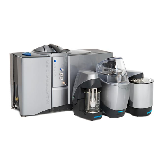
- Page 1 MASTERSIZER 3000 PARTICLE SIZE HYDRO SERIES WET DISPERSION UNITS...
- Page 3 HYDRO SERIES WET DISPERSION UNITS MAN0479-06-EN-00...
- Page 4 Tel + [44] (0)1684-892456 Fax + [44] (0)1684-892789 Malvern® and the “hills” logo are registered trademarks in the UK and/or other coun- tries, and is owned by Malvern Instruments Ltd. Mastersizer 3000® is a registered trademark in the UK and/or other countries, and is owned by Malvern Instruments Ltd.
-
Page 5: Table Of Contents
Table of Contents CONTENTS Contents Introduction Hardware features Hydro series wet dispersion units — overview Hydro MV and LV — basic operation Hydro MV and LV features Hydro EV — basic operation Hydro EV features Hydro SM — basic operation Hydro SM features Hydro SV —... - Page 6 Table of Contents Checking and replacing the sample pipes Cleaning the covers Performing a Quality Audit Standard measurement Power connection, leads and fuses Hydro dispersion unit specific cleaning procedures Consumable kits Appendix Specification Chemical compatibility Regulatory information Index...
-
Page 7: Introduction
INTRODUCTION This manual details the important features of the Mastersizer 3000 Hydro series wet dis- persion units. Dispersion Model Description unit number Hydro SV Small volume (SV) automatic wet dispersion unit MAZ3100 Hydro SM Small volume manual (SM) wet dispersion unit... - Page 8 Introducti on This manual focuses on specific issues of the Hydro series wet dispersion units that are not covered by the above manuals.
-
Page 9: Hardware Features
This section provides information on the typical hardware setup of the dispersion units and provides more detail on the connections available. Topics included are: Hydro series wet dispersion units — overview Hydro MV and LV — basic operation Hydro MV and LV features Hydro EV —... -
Page 10: Hydro Series Wet Dispersion Units - Overview
H ardware features Hydro series wet dispersion units — overview Sample dispersion units prepare and deliver sample to an optical unit so that it can be measured. The Hydro dispersion units create a suspension of particles in liquid media which enables particle-in-liquid size measurements of both aqueous and non-aqueous samples to be made by the Mastersizer. - Page 11 H ardware features Dispersion unit Capacity (ml) Suitability Notes dispersants are either expensive or hazardous. The flexibility of the Hydro EV Measured in a standard labor- allows you to select dispersant atory beaker rather than being Hydro EV 600 - 1000 volumes suitable for certain added and drained auto- applications.
-
Page 12: Hydro Mv And Lv - Basic Operation
H ardware features Hydro MV and LV — basic operation This section provides an overview of the working principles of the Hydro MV and LV. These units operate in essentially the same way; a Hydro LV dispersion unit is shown in this illustration. - Page 13 H ardware features Once measured, the sample can be discharged through the drain outlet, which is again controlled by the software. This outlet is compatible with most aqueous and non- aqueous dispersants. Refer to the Mastersizer 3000 User Manual for advice on sample addition. Note: The lower ‘to cell’...
-
Page 14: Hydro Mv And Lv Features
H ardware features Hydro MV and LV features This section identifies the main features of the Hydro MV (medium volume) and LV (Large volume) dispersion units. A Hydro LV dispersion unit is shown in the below illustration. 10 11 1. Sample tank 2. - Page 15 H ardware features Sample tank The sample tank can hold up to 120 ml (Hydro MV) or 600 ml (Hydro LV) of sample and dispersant prior to circulation through the wet cell situated in the measurement area of the optical bench. The sample tank is normally filled using the dispersant inlet ports, though sample and dis- persant can be poured directly into the tank if required.
- Page 16 H ardware features 1. Tank light 2. Over-flow (castellations) 3. Breather holes 4. Baffles Over-flow system and drain An over-flow is located underneath the metal shield on the top of the sample tank; this is indicated by castellations at the bottom edge of the shield. If too much fluid is filled into the tank, any excess will overflow into here and sub- sequently out of the drain pipe at the rear of the unit.
- Page 17 H ardware features Note: The level sensor in the dispersion unit stops the tank being overfilled above a certain level. This level, when the dispersant is detected and the tank light flashes, depends upon the liquid that has been used in the tank. A threshold value needs to be applied to the level sensor for all liquids other than water.
- Page 18 When an ultrasonic trans- ducer warning is shown contact your Malvern representative for information on how to order a replacement transducer.
- Page 19 A 90 degree support bracket can be fitted to the drain pipe to direct the waste fluid into the drain. Replacement drain pipes are available from Malvern Instruments. Note: Make sure that the drain end of the drain pipe is above the level of the waste liquid at all times.
- Page 20 3. Pull the dispersant pipe gently to make sure it is secure. To remove, press the lock down on the connection and pull pipe to remove. Suitable aqueous pipes are available from Malvern Instruments. Note: Using the Accessory controls in the SOP, the inlet ports can be used to both fill and clean the tank.
- Page 21 The inlet pipe has an outside diameter of 1/4 inch (6.35 mm). Suit- able non-aqueous sample pipes are available direct from Malvern Instruments. Note: Using the Accessory controls in the SOP, the inlet ports can be used for both tank filling, and cleaning.
- Page 22 H ardware features To cell / from cell connections The sample from the dispersion unit is circulated through the cell via ‘to cell’ and ‘from cell’ connections and the connected sample pipes. To cell connection The ‘to cell’ connections on the dispersion unit and wet cell have yellow identifier marks. The bottom connection on the dispersion unit connects to the sample 'out' pipe.
- Page 23 H ardware features Connections CAN connection The CAN connection provides both the communications and power to operate the dis- persion unit. The CAN cable connects from the CAN connection to one of the CAN connections on the side of the optical unit. Auxiliary connector When required, the auxiliary connector (AUX) is used to connect any accessory that can be used with the dispersion unit.
-
Page 24: Hydro Ev - Basic Operation
H ardware features Hydro EV — basic operation This section provides an overview of the working principles of the Hydro EV. The Hydro EV uses a standard laboratory beaker [1] to hold the sample and dispersant liquid. Note: 600 ml and 1000 ml beakers are recommended. The pump head [2] tilts back allowing the insertion of a beaker that contains dispersant. - Page 25 H ardware features When the sample has been measured, the pump arm is raised and the beaker is with- drawn. Refer to the Mastersizer 3000 User Manual for advice on sample addition.
-
Page 26: Hydro Ev Features
H ardware features Hydro EV features This section identifies the main features of the Hydro EV dispersion unit. 1. Sample tray area / beaker 2. Drip tray / beaker holder 3. Pump head 4. Sample pump and stirrer 5. Ultrasonic transducer 6. - Page 27 H ardware features Sample area/beaker The sample beaker holds the sample and dispersant. Beaker specifications: Capacity: 600 ml or 1000 ml Height: 15 cm max. Dispersant is added directly into the beaker, which is then placed onto the sample area drip tray, sample is then added as required.
- Page 28 H ardware features A light, positioned in the base of the pump head above the tank, is used to illuminate both the beaker and the sample fluid within. The sample pump and stirrer (described below) is attached to the bottom of the pump head, whilst an ultrasonic transducer (not shown) within the sample flow path also helps to disperse the sample.
- Page 29 Ultrasonic transducers have a recommended usage lifetime. Mastersizer's software mon- itors usage and indicates the status of this in the notification field. When an ultrasonic transducer warning appears, contact Malvern Instruments to order a replacement. Note: The Ultrasonics will switch off automatically after 20 minutes continuous use.
- Page 30 H ardware features To cell / From cell connections The sample from the dispersion unit is circulated through the cell via ‘to cell’ and ‘from cell’ connections and the connected sample pipes. To cell connection The ‘to cell’ connections on the dispersion unit and wet cell have yellow identifier marks. The bottom connection on the dispersion unit connects to the sample 'out' pipe.
- Page 31 Remove the retaining clips by twisting apart using pliers to separate the teeth, allowing the clip to be removed. Note: Suitable aqueous and non-aqueous wet cell pipes are available direct from Malvern Instruments. Connections CAN connection The CAN connection provides both the communications and power to operate the dis- persion unit.
- Page 32 H ardware features Auxiliary connector When required, the auxiliary connector (AUX) is used to connect any accessory that can be used with the dispersion unit.
-
Page 33: Hydro Sm - Basic Operation
H ardware features Hydro SM — basic operation The Hydro SM is designed for the measurement of samples in non-aqueous dispersants where solvent usage needs to be minimized. This is ideal when the sample or dispersant is toxic or expensive. This section provides an overview of the working principles of the unit. -
Page 34: Hydro Sm Features
H ardware features Hydro SM features This section identifies the main features of the Hydro SM dispersion unit. 1. Dispersion unit and sample tank 2. Sample pump and stirrer 3. Tank cover 4. Drain port and lever 5. To cell / From cell connections 6. - Page 35 H ardware features The sample tank can hold a maximum of 120 ml of sample and dispersant prior to cir- culation through the wet cell situated in the measurement area of the optical bench. Sample and dispersant are poured directly into the tank as required. Caution! Do not overfill the beaker as spillage may occur once the pump starts.
- Page 36 3. Tighten the jubilee clip until fully secure. Removal is the reverse of the procedure. Note: Replacement drain pipes are available direct from Malvern Instruments. To cell / From cell connections The sample from the dispersion unit is circulated through the cell via ‘to cell’ and ‘from cell’...
- Page 37 3. Follow the Hydro MV/LV wet cell connection procedure for connection to the wet cell. Removal is the reverse of the procedure. Make sure the cell is empty before removal. Suitable aqueous and non-aqueous wet cell pipes are available direct from Malvern Instru- ments. Dispersion unit controller...
- Page 38 H ardware features 1. Pump/stirrer speed control 2. Pump speed display 3. Power switch 4. Power and CAN connection 5. Dispersion unit connection Pump/stirrer speed control This control alters the speed of the stirrer / pump and thus the flow rate of sample/ dis- persant through the cell.
-
Page 39: Hydro Sv - Basic Operation
H ardware features Hydro SV — basic operation The Hydro SV liquid dispersion unit enables particle size analysis using small volumes of sample and dispersant, with a particle size typically less than 200 μm. This is ideal when the sample or dispersant is toxic or expensive. 1. - Page 40 H ardware features The complete cell is inserted into the cell bay of the optical unit. With the cell in position, a motor within the cell rotates the stirrer bar that continually circulates the dispersant around the cuvette to make sure it is adequately dispersed prior to a measurement. The stirrer speed is controlled using the Mastersizer software or front panel dial.
-
Page 41: Hydro Sv Features
H ardware features Hydro SV features This section identifies the main features of the Hydro SV dispersion unit. 1. Cell shroud 2. Shutter activation arm 3. Sample cuvette and cuvette lid 4. Cell handle and unlock button 5. Drip tray 6. - Page 42 H ardware features 8. Stirrer speed display 9. Stirrer speed control On/Off 10. Power and CAN connection Note: The Hydro SV dispersion unit will generally be referred to as the "Hydro SV" or "SV cell" or just "cell". Cell shroud assembly The cell shroud prevents the emission of laser radiation.
- Page 43 H ardware features Drip tray Any overspills are captured within the drip tray and drained through a drain port at the front of the cell and optical unit. If any liquid is noticed in the drip tray, remove the cell and tip the contents away.
- Page 44 H ardware features For details on how to fill the cuvette with dispersant and then sample, refer to Filling the cuvette on the facing page. The sample cuvette can be removed to allow cleaning; the cuvette locks are rotated and the complete cuvette can be removed.
- Page 45 H ardware features Stirrer speed control, display and motor Turning on With the Power and CAN cables connected, power the unit ON by pressing on the speed control dial; pressing again will turn the unit OFF. The Hydro SV does not need to be located into the cell bay of the optical unit before it can be turned on.
- Page 46 H ardware features The technique to fill the cuvette used with the Hydro SV is the same as for any cuvette; make sure that the dispersant is carefully injected into the cuvette with the minimum of bubbles produced. The cuvette is filled and inserted into the SV cell while the cell is out of the optical unit. Note: Try not to use dispersants with too high a viscosity.
- Page 47 H ardware features Filling the cuvette 1. Hold the cuvette at an angle, and with the syringe tip placed along an inner side of cuvette, carefully inject the sample. The sample will flow along the side of the cuvette and slowly fill it up. 2.
- Page 48 H ardware features 5. Place the cuvette lid on to the cuvette and place into the SV cell. Datum/location points in the corners of the cuvette holder aid correct insertion. The spout on the top of the cuvette must face the front of the cell once inserted. 6.
- Page 49 H ardware features 9. Place the SV cell into the cell bay of the optical unit and start the measurement. Adding sample Take a pipette and draw the sample into it — fill until the maximum fill mark is reached (maximum 1 ml).
- Page 50 H ardware features 4. Press Start to continue and complete the measurement. When not in optical unit: 1. When the measurement requests the sample to be added, press the unlock but- ton on the cell handle and remove the cell. 2.
- Page 51 H ardware features 5. Take the cuvette and place into the SV cell. Secure with the cuvette locks. 6. The stirrer bar will attach to the stirrer motor. 7. Press the speed dial to turn the Hydro SV on and test the SV operates correctly; the stirrer bar should spin.
- Page 52 H ardware features 1. First, fill the cuvette with dispersant (6 ml minimum). 2. Insert the cuvette into the SV cell and then the instrument. Perform a background and initial alignment. 3. The SV cell can then be removed and, using the syringe (with syringe tip attached), extract an amount of dispersant.
-
Page 53: Hydro Series Wet Cell
The flow cell is an optical device. Scratches to the surfaces of the cell may affect performance. Each Hydro dispersion unit will be connected to a Hydro series wet cell. Two wet cells are available, for use with aqueous or non-aqueous based samples. - Page 54 H ardware features Features of the wet cell 1. Cell shroud 2. Mechanical shutter activation arm 3. Sample wet cell, cell windows and seals 4. Cell handle and unlock button 5. Drip tray 6. To cell/ From cell connections 7. Water jacket connections (Heat exchanger)
- Page 55 H ardware features Cell shroud The cell shroud prevents human access to laser radiation. It also prevents stray light affect- ing a measurement and reduces noise emissions. The cell shroud incorporates a mechanical shutter arm that opens when inserted into the optical unit —...
- Page 56 H ardware features To ensure optimal location prior to measurements being performed, a lock motor secures the cell into a defined position when the cell is inserted into the sample area. To remove the cell: 1. Press the unlock button on the cell handle. 2.
- Page 57 H ardware features Connecting the wet cell sample pipes. To connect the wet cell pipes: 1. Using the supplied spanner or with fingers, unscrew the connection cap. 2. Insert the cap over the wet cell pipe. 3. Push the sample pipe onto the connection. 4.
- Page 58 H ardware features 1. Water jacket connections (inlet/outlet ports) 2. Water jacket The Heat exchanger consists of a 'jacket’ that surrounds the flow cell connection pipes. Cooling/heating liquid is fed into this jacket to cool/heat the sample. The heat exchanger can be used for two functions: To heat or cool the sample so that sample measurements can be performed at dif- ferent temperatures.
- Page 59 H ardware features Always fill from the bottom inlet connection â. This is to prevent any air bubbles being caught in the heat exchanger arrangement. For most applications the heater/chiller fluid will be water. Refer to the Mastersizer 3000 User Manual and Basic Guide for the site require- ments of the heater/ chiller fluid connections.
-
Page 60: Connection Of The Dispersion Units
H ardware features Connection of the dispersion units Connection of the dispersion units is described in this section. The Mastersizer 3000 User Manual details specific connections to the optical unit. Hydro LV and MV connections 2m max Figure 2-1: Hydro LV and MV connections. - Page 61 Note: Discharge to a normal sink is sufficient, provided the sample and dis- persant are non-hazardous. Note: If connecting an external dispersant pump to the Hydro LV or MV units, refer to External dispersant pump in the Hydro series wet dispersion units manual...
- Page 62 H ardware features Hydro EV connections Figure 2-2: Hydro EV connections. 1. Power cable from external PSU 2. CAN cable 3. Computer connection (USB) 4. Sample pipes to and from cell 5. Heater / chiller connections (optional)
- Page 63 H ardware features Hydro SM connections Figure 2-3: Hydro SM connections. 1. Power cable from External PSU 2. CAN cable 3. Computer connection (USB) 4. Sample pipes to and from cell...
- Page 64 H ardware features 5. Heater/chiller connections 6. Controller unit connection 7. Drain pipe to waste To allow liquid to drain efficiently the drain/waste must: Be within 2 m of the dispersion unit Be lower than the bench surface Slope gently downwards Contain no loops or kinks.
- Page 65 H ardware features Hydro SV connections Figure 2-4: Hydro SV connections. 1. Power cable from External PSU 2. CAN cable 3. Computer connection (USB)
- Page 66 Malvern supplied peristaltic pump Malvern supplies an external peristaltic pump that can be connected and plumbed into the Hydro LV and Hydro MV dispersion units. The pump will be used in conjunction with the software, and activated when a specific fill or clean routine is selected.
- Page 67 3. Connect the auxiliary control cable [2] from the dispersant unit into the rear of the pump. The pump must be set for Analogue-Automatic operation mode using the control cable and Malvern software (Auto restart mode). In this mode the pump will automatically start in automatic mode when turned on. To do this: 1.
- Page 68 H ardware features Note: With the auxiliary control cable connected and the pump set to auto mode, manual mode will not be available. Warning! If the auxiliary cable is disconnected when the power is still supplied the pump will briefly rotate. This may deposit any dispersant present in the pipes. Pipe connection The pumphead [2] is uni-directional and travels anti-clockwise.
- Page 69 An ancillary switch unit is available to allow an external pump to be controlled from the Hydro LV and Hydro MV dispersion units. This allows dispersant to be supplied from an unpressurized tank or flask. Contact Malvern Instruments for more details. Setup and control The ancillary switch unit will activate the connected pump using the same software com- mands as indicated above.
-
Page 71: Software Overview
SOFTWARE OVERVIEW This section describes the software controls and explains how to use these to make and ana- lyze measurements on the system. Topics included are: Making a measurement Control of a dispersion unit via an SOP Accessory controls panel Manually controlled accessories... -
Page 72: Making A Measurement
Software overvi ew Making a measurement How to make a Measurement with the Mastersizer 3000 dispersion units is fully doc- umented in the Mastersizer 3000 User Manual. Refer to that manual for details. The dispersion units can be controlled in several ways; Automatically —... -
Page 73: Accessory Controls Panel
Software overvi ew Accessory controls panel Note: Only available with the Mastersizer 3000 / Mastersizer 3000E with Exten- ded software option. Users with the Basic software feature set control the dis- persion unit with the Accessories option on the Tools ribbon. Use the Accessory controls panel from the manual measurement mode to control the attached accessory independently of the measurement process. -
Page 74: Manually Controlled Accessories
Software overvi ew Manually controlled accessories Manually controlled accessories may also be connected to the optical unit. These accessor- ies do not have an automated or manual software control, but will be controlled directly from the control interface on the accessory itself. Like the automatic controlled dispersion units, manual accessories are selected from the SOP Editor: 1. -
Page 75: Maintenance
MAINTENANCE This section provides information and instructions for the maintenance of the dispersion units. This includes a maintenance schedule and associated maintenance procedures for each dispersion unit and its respective components. Specific procedures for how to inspect and clean the cell windows are described. Topics included are: Introduction and warnings Maintenance schedule... -
Page 76: Introduction And Warnings
Mai ntenance Introduction and warnings The topics in this section cover all the user maintenance procedures for the dispersion units. Do not attempt any maintenance procedure not specified here. Note: Maintenance procedures for the Mastersizer 3000 optical unit can be found in the Mastersizer 3000 Basic Guide. -
Page 77: Maintenance Schedule
Mai ntenance Warning! Before cleaning, always disconnect the unit from the power supply and com- puter and disconnect all electrical cables. Make sure the unit is completely dry before re-applying power. Maintenance schedule Follow the maintenance schedule below to keep the Hydro dispersion unit working well. This list is only a guide;... - Page 78 Mai ntenance If the dispersant type is changed, or if sample is seen to adhere to the Clean the sample tank sample tank and the normal flush routine fails to remove it Replace the dispersant If the dispersant pipe leaks or becomes discolored. This may allow pipe bubbles to enter, causing rapid fluctuations in the background.
- Page 79 Check cuvette body for Periodically check for leaks from the cuvette body. if leaks occur or dam- leaks and damage age is visible contact Malvern instruments Clean as necessary. Check for damage and make sure guide pipe align- Pipette guide pipe...
-
Page 80: Cell Windows - Inspection For Poor Background
Mai ntenance Clean the area where the cuvette is positioned. Inspect cell holder Check condition of the cuvette locks – do they work correctly. Cell windows — inspection for poor background Inspect the cell windows for cleanliness every day and after each measurement session. Material stuck to windows Significant scattering on the detector channels, as shown below [1], often indicates that fine material is stuck to the cell windows:... - Page 81 Mai ntenance Bubbles may enter the system because of high pump or stirrer speeds with viscous dis- persants or those containing surfactants, or due to leaking pipes or seals. Check and replace any damaged pipes or seals as described in Checking and replacing the sample pipes on page 93.
-
Page 82: Cell Windows - Removal And Inspection
Standard laboratory gloves should also be used when handling the wet cell seals. Malvern recommends disposable, powder free, nitrile (NBR) gloves. Removing a cell window: 1. Remove all sample from the system, then remove the wet cell from the system. - Page 83 Mai ntenance 2. Hold a cover plate slightly above a clean lens tissue, and place another lens tissue over the cell window area. With light pressure push the cell window and seal out from the cover plate onto the bottom lens tissue.
- Page 84 Mai ntenance 3. Hold onto the ends of the seal and turn the cell seal and window assembly over on to the lens tissue, so the seal is on top of the lens. 4. Hold the center of the cell window down with another lens tissue, then take hold of the longest end of the seal, and lift the seal clear of the window.
- Page 85 Inspecting and cleaning a cell window 1. Inspect both sides of the cell window. If there are traces of scratches replace the windows. Spare windows can be obtained from Malvern Instruments. 2. Remove any dust on the window surfaces using a compressed gas duster can.
-
Page 86: Cell Windows - Cleaning Procedures
Lens tissues should be placed over the window faces where necessary. Use standard laboratory gloves in all cell seals, cell cover plates and cell windows maintenance procedures. Malvern recommends dis- posable, powder free, nitrile gloves. General guidelines Keep optical components as clean as possible to prevent additional light scattering from dust particles affecting your measurement. - Page 87 Mai ntenance Gritty surface particles/smeared surface — with grit If the surface has fingerprints on it or has not been cleaned for a long time, assume there is grit present. First wash the surface then wipe it as described; refer to the Washing cell windows and Wiping cell window sections below.
- Page 88 Mai ntenance Procedure Caution! Throughout this procedure, apply only minimal pressure to the surface with the brush. Never rub with the brush. Note: Greasy smears or O-ring marks will not be removed by this process – see the Wiping cell windows section below for information on this. 1.
- Page 89 Mai ntenance Once the dust is removed, wipe the cell windows as described in the Wiping cell windows section below to produce the final clean surface. Brushing optical surfaces Note: Avoid a typical “brush” action; as the brush is moved sideways grit trapped in the brush is dragged across the surface leaving scratches.
- Page 90 Mai ntenance 2. Grip the tissue about half way down, dampen the edge of the tissue with a small quantity of ethanol (too much will flood the tissue). Allow the ethanol to soak in. 3. Note any marks and smears. Inspect the window in reflected light from a fluor- escent light or other light source.
-
Page 91: Cell Windows - Replacing And Re-Assembling
Mai ntenance Cell windows — replacing and re-assembling The procedures below detail how to fit a new cell window into the cell seal and reinsert it into the wet cell plate/holder. Take the same precautions when reusing the existing cell window after its cleaned;... - Page 92 Mai ntenance paper wrapping. Hold by ground edges of window. 3. Insert the cell window in to the circular section of the seal. Note: Make sure that the larger diameter faces down when inserted in to the cell seal. 4. Place the wet cell cover plate on to a flat surface. The seal cavity must face up. 5.
- Page 93 Mai ntenance 8. The seal in its fitted position. 9. Once finished: The circular section of the seal must be flush with the flat surface of the measurement area of the cover plate and the glass. It cannot bulge out or sit below the surface (A).
- Page 94 Mai ntenance over the circular window seal section (B). The section of the seal with the flat seal face must be located fully into the seal cavity, edge to edge 10. Remove any lubricant, as described below Repeat the above procedure when replacing the cell seal/window assembly into the main body of the cell.
-
Page 95: Checking And Replacing The Sample Pipes
2. Push the new pipes onto the pipe boss to a minimum of 7 mm. 3. Then secure, where fitted, with the aluminum pipe connectors The sample pipe originally supplied by Malvern is Tygon available from Cole-Parmer Instru- ment Company. Tygon is chemically compatible with a wide range of materials. Contact the manufacturer for full information on compatibility. -
Page 96: Cleaning The Covers
Never clean with a solvent based solution; it may damage the surface. Performing a Quality Audit Standard measurement Malvern supplies a Quality Audit Standard (QAS) specifically designed to test the per- formance of the dispersion unit. It is recommended this is performed at least once a week or as an internal quality procedure. -
Page 97: Hydro Dispersion Unit Specific Cleaning Procedures
Mai ntenance Hydro dispersion unit specific cleaning procedures This section provides information about dispersion unit specific procedures. Hydro MV/LV procedures Cleaning the flow path Rinse fresh dispersant through the cell windows, system pipes and sample flow path a couple of times. This is usually sufficient to prepare the system prior to a new meas- urement;... - Page 98 Mai ntenance Inspect the sample head weekly. If it needs to be cleaned, disconnect the dis- persion unit from the mains power and use a bottle brush to clean it. Use a deter- gent (e.g. Decon 90) if necessary. Rinse the head thoroughly to remove all detergent traces.
- Page 99 Mai ntenance Hydro SV procedures Cuvette and stirrer bar cleaning — general internal wash Note: The cuvette must not be taken apart for cleaning. Users should only fol- low the maintenance procedures specified. Note: The cuvette and stirrer bar should be cleaned thoroughly before first use and before any subsequent measurements are performed.
- Page 100 Mai ntenance 1. Place the cuvette upside down in the wash station. Ensure correct orientation and the cuvette is firmly in place. The spout should face away from the waste exit/ dis- persant input. 2. Fill a syringe with some IPA. Warning! Make sure the cuvette is fitted correctly before using the syringe, otherwise you may be sprayed with dispersant or other cleaning chemicals.
- Page 101 Mai ntenance 1. Clean the cuvette as above then do a final flush with IPA. This will remove any smears or marks that may occur after cleaning with deionised water. 2. Clean the stirrer bar with IPA using a lint free cloth. 3.
- Page 102 Mai ntenance Cuvette cleaning — intensive internal window clean For a more intense clean of the internal faces and edges of the cuvette, use an optics qual- ity cleaning cloth and the cuvette cleaning spatula. These are included in the consumable kit supplied with the Hydro SV.
- Page 103 Follow the below guidelines for cleaning and handling the stirrer bar 1. Clean the stirrer bar in a small amount of IPA. 2. It is recommended to use the Malvern supplied stirrer bar. Other stirrer bars may have a different diameter and different magnetic qualities that may affect the sample dispersion within the cuvette, as well as its coupling to the stirrer motor.
-
Page 104: Consumable Kits
Mai ntenance Consumable kits Consumable kits and additional spares for maintaining the Hydro series wet dispersion units are available from your Malvern representative. Please contact them for full details and requirements. The consumable kits include the following components: Hydro LV consumable kit... - Page 105 Mai ntenance Solvent resist wet cell windows and seals pack Standard wet cell windows and seals pack (FKM) (FFKM) Hydro SV consumable kit SV cell 10 ml disposable syringe and needle attachment Stirrer bar Lint free wipes Pipette Cuvette cleaning spatula and cloth Wash station drain pipe...
-
Page 107: Appendix
APPENDIX This section details the specifications of each dispersion unit and identifies the chemical compatibility of any components that may come into contact with the sample. Additionally, it provides the important regulatory information to which the dispersion units are com- pliant. -
Page 108: Specification
Appendi x Specification All specifications correct at time of publication, but may be subject to alteration. Hydro MV / Hydro LV Item Specification Dispersion type Capacity — Hydro MV 120 ml — Hydro LV 600 ml Typical applications — Hydro MV Solvent-based suspensions, Pharmaceuticals. - Page 109 Appendi x Hydro EV Item Specification Dispersion type Capacity 600 ml / 1000 ml (standard laboratory beaker) Sonication power / frequency 40 W max, 40 kHz (nominal)* * Dispersant dependent. Typical applications Minerals, fillers, chemicals, foodstuffs, emulsions Dispersion mechanisms Continuously variable pump / stirrer and ultrasonics. Modes of operation Automatic via SOPs.
- Page 110 Appendi x — Controller unit 1 kg — Dispersion unit 8.75 kg Dimensions — Controller unit Width: 70 mm / Height: 225 mm / Depth: 170 mm — Dispersion unit Width: 390 mm / Height: 140 mm / Depth: 175 mm Power Supplied via CAN cable from the Optical unit Power consumption...
- Page 111 Appendi x Hydro series wet cell Item Specification Weight 2.46 kg Dimensions Width: 106 mm / Height: 273 mm / Depth: 227 mm Liquid temperature range 0 to 50°C (water jacket connections) 0.5 bar g Maximum pressure (water jacket connections)
- Page 112 Appendi x Stirrer PEEK (Glass fiber reinforced) Impeller Stainless steel 316 / PEEK Ultrasonic transducer Stainless steel 316 / Titanium nitride / PTFE Sample flow pipe Stainless steel 316 / PEEK (Natural) / FFKM / PTFE/ (internal) Sample flow pipe Tygon (external to wet cell) Wet cell assembly...
- Page 113 Borosilicate Glass / Stainless steel 316 / FKM or FFKM Note: For the Hydro MV / LV Fluoroelastomer (FKM) seals in the wet cell can be upgraded to Perfluoroelastomer FFKM to improve the chemical compatibility. Contact your Malvern representative for details. Perilstaltic pump Component...
-
Page 114: Regulatory Information
Appendi x Stirrer bar PTFE Wash station Stainless steel 316 Regulatory information Regulatory information for all Mastersizer 3000 instruments and dispersion units, can be found in the Mastersizer 3000 Basic Guide. -
Page 115: Index
Hydro SV connections 63 INDEX Specifications 106 Hydro EV Features 24 Hydro LV/MV Cell windows Features 12 Cleaning 84 Hydro SM Cleaning Features 32 Covers 94 Hydro SV Connections 21, 29 Cuvette 43 Hydro EV 60 Features 39 Hydro LV/MV 58 Hydro SM 61 Hydro SV 63 Making a measurement 70... - Page 116 Malvern Instruments Limited Grovewood Road, Malvern Worcestershire, WR14 1XZ, UK +44 1684 892456 +44 1684 892789 www.malvern.com MAN0479 MRK1955-01...
Need help?
Do you have a question about the HYDRO Series and is the answer not in the manual?
Questions and answers
I work with a malvern mastersizer Hydro ev and even when i put the diluent only, my background values start from 2000 to 2500 and not from values <100 as in the maunal. I think the window glass need to be changed. How much is the cost for this spare parts?