Table of Contents
Advertisement
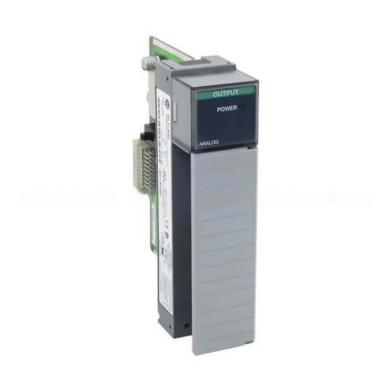
SLC 500™ Analog I/O Modules
(Catalog Numbers 1746-NI4, -NIO4I, -NIO4V, -NO4I,
-NO4V, -FIO4I, and -FIO4V)
Inside...
Important User Information ...................................................... 2
For More Information ............................................................... 3
Types of Analog Modules ......................................................... 4
Hazardous Location Considerations ......................................... 7
Environnements dangereux....................................................... 7
Choosing a Slot in the Chassis ................................................ 10
Installing Your Module ........................................................... 11
Wiring Considerations............................................................. 13
Wiring the Analog Module...................................................... 15
Labeling and Installing the Terminal Block............................ 16
Minimizing Electrical Noise on Analog Modules .................. 17
Specifications .......................................................................... 22
Installation Instruction
page
Publication 1746-IN008A-US-P
Advertisement
Table of Contents


Need help?
Do you have a question about the SLC 500 1746-NI4 and is the answer not in the manual?
Questions and answers