Summarization of Contents
Preface
Additional Resources
Provides links to related Rockwell Automation publications and resources for further information.
Chapter 1 Analog I/O Module Operation in a Logix5000 Control System
Ownership
Defines the controller-owner relationship for I/O modules and its responsibilities.
Construct a 5069 Compact I/O System
Outlines the minimum components required to build a 5069 Compact I/O system.
Input Module Operation
Explains how analog input modules scan channels and transmit data to the controller.
Output Module Operation
Describes how controllers send data to output modules and how modules echo data.
Listen Only Mode
Details how other controllers can monitor module data without owning it.
Chapter 2 Common Analog I/O Module Features
Rolling Timestamp of Data
Explains the 15-bit rolling timestamp used for tracking data sample timing.
Module Data Quality Reporting
Describes how modules indicate data accuracy using Fault and Uncertain tags.
Software Configurable
Highlights that module features are managed via the Logix Designer application.
Electronic Keying
Explains how to ensure the correct device is used by comparing project and installed device attributes.
Alarm Latching
Details how to keep alarms active even after the triggering condition resolves.
Chapter 3 Current/Voltage Analog Input Module Features (5069-IF8)
Module Features
Lists the key features of the 5069-IF8 module, such as input ranges and filters.
Multiple Input Ranges
Describes the configurable input ranges available for the 5069-IF8 module based on input type.
Notch Filter
Explains the function of the Notch Filter in removing line noise from input signals.
Digital Filter
Details the first-order lag filter used to smooth input data transients.
Process Alarms
Covers how to configure high/low limits to generate process alarms for each channel.
Chapter 4 Current/Voltage/Temperature-sensing Analog Input Module Features (5069-IY4)
Module Features
Lists the features specific to the 5069-IY4 module, including sensor types.
Multiple Input Ranges
Describes the various input ranges supported by the 5069-IY4 for different input types like RTD and Thermocouple.
Sensor Types
Details the available sensor types that can be used with the 5069-IY4 module.
Cold Junction Compensation
Explains the need and method for cold junction compensation with thermocouple inputs.
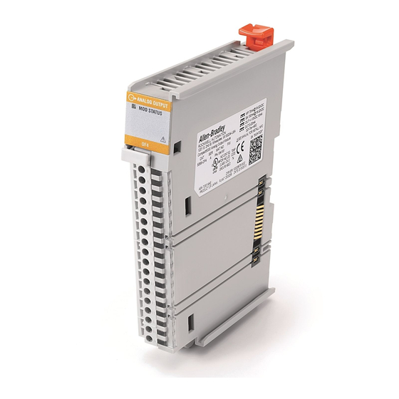
Chapter 5 Current/Voltage Analog Output Module Features (5069-OF4, 5069-OF8)
Module Features
Lists the features of the 5069-OF4 and 5069-OF8 analog output modules.
Output Clamping
Explains how to limit output signals to a configured range, preventing out-of-range commands.
Output Ramping/Rate Limiting
Describes how to control the speed of output signal changes to prevent damage to controlled devices.
Fault and Status Reporting
Details how output modules report fault and status data via module tags and indicators.
Chapter 6 Configure the Module
Before You Begin
Lists the prerequisite tasks before configuring the analog I/O modules.
Create a New Module
Guides users on adding new modules to the Logix Designer project via discovery or manual addition.
Edit the Module Configuration Common Categories
Explains how to access and modify common configuration parameters for modules.
Module Definition
Describes the parameters that define a module's behavior and available choices.
Connection Category
Details how to configure connection parameters like RPI and connection type for modules.
Module Info Category
Explains how to view module identity, status, and access diagnostics within the project.
Chapter 7 Calibrate the Module
Before You Begin
Outlines considerations before starting the module calibration process.
Difference Between Calibrating an Input Module and an Output Module
Highlights procedural differences in calibrating input versus output modules.
Calibrate the Input Modules
Provides step-by-step instructions for calibrating input modules using reference signals.
Calibrate the Output Modules
Details the process for calibrating output modules using a multimeter to measure signal levels.
Appendix A Troubleshoot Your Module
Module Status Indicator
Explains the meaning and recommended actions for the module's status indicator states.
5069 Compact I/O Analog Input Modules Status Indicators
Illustrates and describes status indicators for analog input modules.
5069 Compact I/O Analog Output Modules Status Indicators
Illustrates and describes status indicators for analog output modules.
Use the Logix Designer Application for Troubleshooting
Describes how to use Logix Designer to identify and diagnose module faults.
Appendix B Module Tag Definitions
Tag Name Conventions
Explains the standardized naming conventions used for module tags in Logix Designer.
Access the Tags
Provides steps on how to view module tags within the Logix Designer application.
5069-IF8 Module Tags
Lists and defines configuration, input, and output tags specific to the 5069-IF8 module.
5069-IY4 Module Tags
Lists and defines configuration, input, and output tags specific to the 5069-IY4 module.
5069-OF4, 5069-OF8 Module Tags
Lists and defines configuration and input/output tags for 5069-OF4/OF8 modules.


Need help?
Do you have a question about the 5069-OF4 and is the answer not in the manual?
Questions and answers