Table of Contents
Advertisement
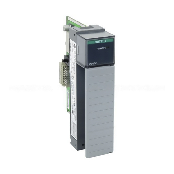
SLC 500™ Analog I/O Modules
(Catalog Numbers 1746-NI4, -NIO4I, -NIO4V, -NO4I,
-NO4V, -FIO4I, and -FIO4V)
Inside...
Important User Information ...................................................... 2
For More Information ............................................................... 3
Types of Analog Modules ......................................................... 4
Hazardous Location Considerations ......................................... 7
Environnements dangereux....................................................... 7
Choosing a Slot in the Chassis ................................................ 10
Installing Your Module ........................................................... 11
Wiring Considerations............................................................. 13
Wiring the Analog Module...................................................... 15
Labeling and Installing the Terminal Block............................ 16
Minimizing Electrical Noise on Analog Modules .................. 17
Specifications .......................................................................... 22
Installation Instruction
page
Publication 1746-IN008A-US-P
Advertisement
Table of Contents

Related Manuals for Allen-Bradley SLC 500 1746-NIO4V


Summarization of Contents
For More Information
Related Publications
Lists related documents for further details on configuration, installation, and operation.
Types of Analog Modules
1746-NI4 Analog Input Module
Details the 4-channel analog input module, selectable for voltage or current.
1746-NO4I and NO4V Analog Output Modules
Covers 4-channel analog output modules for current and voltage applications.
1746-NIO4I and NIO4V Analog Combination Modules
Explains 2-input/2-output modules with selectable current or voltage input.
1746-FIO4I and FIO4V Fast Analog Combination Modules
Introduces fast response 2-input/2-output modules for high-speed applications.
Analog Modules Operation
Explains how analog modules convert input signals to binary values for the SLC processor.
Configuring Your Module
Switch Settings for the 1746-NI4
Explains how to use DIP switches on the NI4 module to configure channels for current or voltage input.
Module Configuration Settings
Switch Settings for the 1746-NIO4I, -NIO4V, -FIO4I, and -FIO4V
Details DIP switch configuration for NIO4I, NIO4V, FIO4I, and FIO4V modules for input modes.
External Power Switch for the 1746-NO4I and -NO4V
Describes the external power switch for NO4I and NO4V modules, allowing selection of power source.
Wiring Considerations
System Wiring Guidelines
Provides best practices for wiring analog modules, including common terminal usage and voltage/current limits.
Cable Preparation and Grounding
Grounding Your Cable
Instructions on proper grounding of Belden cable drain wire and foil shield for input and output channels.
Determining the Cable Length
Guidance on calculating the required cable length for connecting analog modules.
Cable Preparation
Cable Preparation END 1
Illustrates the preparation of one end of the cable for wiring.
Cable Preparation END 2
Illustrates the preparation of the other end of the cable for wiring.
Wiring Schematics for 2, 3, and 4-Wire Analog Input Devices
2-Wire Transmitter
Wiring schematic for a 2-wire analog input transmitter.
3-Wire Transmitter
Wiring schematic for a 3-wire analog input transmitter.
4-Wire Transmitter
Wiring schematic for a 4-wire analog input transmitter.
General Analog Input Specifications for NI4, NIO4I, NIO4V, FIO4I, and FIO4V
Other Analog Input Specification for FIO4I, and FIO4V
Specific input specifications for the FIO4I and FIO4V modules.
Need help?
Do you have a question about the SLC 500 1746-NIO4V and is the answer not in the manual?
Questions and answers