
Related Manuals for Allen-Bradley 5069-IY4


Summary of Contents for Allen-Bradley 5069-IY4
- Page 1 User Manual 5000 Series Analog I/O Modules in Logix5000 Control Systems Catalog Numbers 5069-IF8, 5069-IY4, 5069-OF4, 5069-OF8...
- Page 2 Regulatory requirements for safe work practices and for Personal Protective Equipment (PPE). Allen-Bradley, Compact I/O, ControlLogix, Integrated Architecture, Logix5000, Rockwell Automation, Rockwell Software, and Studio 5000 Logix Designer are trademarks of Rockwell Automation, Inc. Trademarks not belonging to Rockwell Automation are property of their respective companies.
-
Page 3: Table Of Contents
Rolling Timestamp of Data ........26 Rolling Timestamp with the 5069-IF8 Module Features and 5069-IY4 Modules . - Page 4 Multiple Input Ranges ........38 Module Features (5069-IF8) Notch Filter .
- Page 5 Module Info Category ........91 Edit 5069-IF8 Module Configuration Categories ....92 Channels Category .
- Page 6 Calibrate the Input Modules ........112 Calibrate the 5069-IF8 Module ....... 112 Calibrate the 5069-IY4 Module.
-
Page 7: Additional Resources
These resources contain information about related products from Additional Resources Rockwell Automation. Resource Description 5069 Compact I/O Analog 8-channel Current/ Describes how to install and wire the 5069-IF8 analog Voltage Input Modules Installation Instructions, input module. publication 5069-IN010 5069 Compact I/O Analog 4-channel... - Page 8 You can view or download Rockwell Automation publications at http:// www.rockwellautomation.com/literature/. To order paper copies of technical documentation, contact your local Allen-Bradley distributor or Rockwell Automation sales representative. Rockwell Automation Publication 5000-UM005B-EN-P - November 2015...
- Page 9 Chapter Analog I/O Module Operation in a Logix5000 Control System Topic Page Before You Begin Types of 5069 Compact I/O Analog I/O Modules Ownership Construct a 5069 Compact I/O System Configure a 5069 Compact I/O System Input Module Operation Output Module Operation Listen Only Mode Use 5069-ARM and 5069-FPD Modules Protected Operations...
-
Page 10: Before You Begin
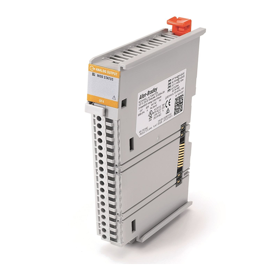
5069 Compact I/O analog I/O modules. Types of 5069 Compact I/O Analog I/O Modules Table 1 - 5069 Compact I/O Analog I/O Modules Cat. No. Description 5069-IF8 8-channel current/voltage input module 5069-IY4 4-channel current/voltage/RTD/Thermocouple input module 5069-OF4 4-channel current/voltage output module... - Page 11 Analog I/O Module Operation in a Logix5000 Control System Chapter 1 Figure 1 shows the parts of an example 5069 Compact I/O analog I/O module. Figure 1 - Example 5069 Compact I/O Analog I/O Module Item Description Status indicators - Displays the status of communication, module health, and input/output devices. Indicators help with troubleshooting anomalies.
-
Page 12: Ownership
Chapter 1 Analog I/O Module Operation in a Logix5000 Control System Ownership Every I/O module in a Logix5000 control system must be owned by a controller, also known as the owner-controller. When the 5069 Compact I/O analog I/O modules are used in a Logix5000 control system, the owner-controller performs the following: •... -
Page 13: 5069 Compact I/O System Power
Analog I/O Module Operation in a Logix5000 Control System Chapter 1 5069 Compact I/O System Power The 5069-AEN2TR EtherNet/IP adapter provides system-side and field-side power to a 5069 Compact I/O system. • System-side power that powers the 5069 Compact I/O system and lets modules transfer data and execute logic. - Page 14 Chapter 1 Analog I/O Module Operation in a Logix5000 Control System Because part of module configuration includes a slot in the 5069 Compact I/O system, the owner-controller checks for the presence of a module there. If a module is detected, the owner-controller sends the configuration. One of the following occurs: •...
- Page 15 Analog I/O Module Operation in a Logix5000 Control System Chapter 1 Data Types Available with 5069 Compact I/O Analog I/O Modules The Module Definition includes a Data parameter that matches the module type. Analog input modules use Input Data, and analog output modules use Output Data.
-
Page 16: Connection Over Ethernet/Ip
Chapter 1 Analog I/O Module Operation in a Logix5000 Control System Connection Over EtherNet/IP During module configuration, you must configure the Connection over EtherNet/IP parameter. The configuration choice dictates how input data is broadcast over the network. The 5069 Compact I/O analog I/O modules use one of the following methods to broadcast data: •... -
Page 17: Controller To Input Module Data Transmission
Analog I/O Module Operation in a Logix5000 Control System Chapter 1 Controller to Input Module Data Transmission The following events occur when the controller sends data to the input module. 1. One of the following: • If the controller is directly connected to the EtherNet/IP network, it broadcasts the data to the network. -
Page 18: Controller To Output Module Data Transmission
Chapter 1 Analog I/O Module Operation in a Logix5000 Control System Controller to Output Module Data Transmission The controller broadcasts data to its local backplane at one of the following: • RPI • An Immediate Output (IOT) instruction is executed. An IOT instruction sends data to the output module immediately, and IMPORTANT resets the RPI timer. -
Page 19: Output Module To Controller Data Transmission
Analog I/O Module Operation in a Logix5000 Control System Chapter 1 Output Module to Controller Data Transmission When an output module receives new data and the requested data value is present on the RTB, the output module sends, or ‘echoes’ , a data value back to the controller and to the rest of the control system. -
Page 20: Listen Only Mode
Chapter 1 Analog I/O Module Operation in a Logix5000 Control System Listen Only Mode Any controller in the system can listen to the data from an I/O module. An owner-controller, as described in Ownership on page 12, exchanges data with the analog I/O module. -
Page 21: 5069-Arm Address Reserve Module
Analog I/O Module Operation in a Logix5000 Control System Chapter 1 5069-ARM Address Reserve Module The 5069-ARM address reserve module reserves a node address in a 5069 Compact I/O system. The module remains installed until you insert another 5069 Compact I/O module into the same location. For example, your application can require the use of a 5069-IB16 module in a specific node location. -
Page 22: 5069-Fpd Field Potential Distributor
Chapter 1 Analog I/O Module Operation in a Logix5000 Control System 5069-FPD Field Potential Distributor The 5069-AEN2TR EtherNet/IP adapter is the primary source of field-side power in the system. However, you can use a 5069-FPD field potential distributor to break field-side power distribution in a 5069 Compact I/O system. Field-side power begins at the 5069 Compact I/O EtherNet/IP adapter is passes across the internal circuitry of the 5069 Compact I/O modules to the right. -
Page 23: Protected Operations
Analog I/O Module Operation in a Logix5000 Control System Chapter 1 Protected Operations To ensure the secure operation of your 5069 Compact I/O analog I/O module, operations that can disrupt module operation are restricted based on the module operating mode. Table 3 describes the restrictions. - Page 24 Chapter 1 Analog I/O Module Operation in a Logix5000 Control System Notes: Rockwell Automation Publication 5000-UM005B-EN-P - November 2015...
- Page 25 Chapter Common Analog I/O Module Features Topic Page Rolling Timestamp of Data Floating Point Data Format Calibration Module Data Quality Reporting Software Configurable Fault and Status Reporting Module Inhibiting Electronic Keying Producer-Consumer Communication Status Indicators Alarm Latching Scaling Data Offset Module Accuracy Module Firmware 5069 Compact I/O™...
-
Page 26: Rolling Timestamp Of Data
The rolling timestamp value is reported in the I.Chxx.RollingTimestamp tag for the 5069 Compact I/O analog I/O modules. Rolling Timestamp with the 5069-IF8 and 5069-IY4 Modules Typically, the 5069 Compact I/O analog input modules scan their inputs at the RPI. The module also updates the rolling timestamp data at the RPI. The controller program uses the last two rolling timestamp values to calculate the amount of time between the samples. -
Page 27: Module Data Quality Reporting
Common Analog I/O Module Features Chapter 2 Module Data The 5069 Compact I/O analog I/O modules indicate the quality of channel data that is returned to the owner-controller. Data quality represents accuracy. There Quality Reporting are levels of data quality reported via module input tags. The following input tags indicate the level of data quality. -
Page 28: Calibration Causes Uncertain Data Quality Indication On Input Module Groups
Chapter 2 Common Analog I/O Module Features Calibration Causes Uncertain Data Quality Indication on Input Module Groups When a channel on a 5069 Compact I/O analog input module is being calibrated, the Notch Filter setting for that channel changes to 5 Hz. This results in the I.Chxx.Uncertain tag being set to 1 for that channel until calibration is completed. -
Page 29: Fault And Status Reporting
Common Analog I/O Module Features Chapter 2 Fault and Status Reporting The 5069 Compact I/O analog I/O modules report fault and status data along with channel data. Fault and status data is reported in the following ways: • Logix Designer application •... -
Page 30: Electronic Keying
Chapter 2 Common Analog I/O Module Features Electronic Keying Electronic Keying reduces the possibility that you use the wrong device in a control system. It compares the device defined in your project to the installed device. If keying fails, a fault occurs. These attributes are compared. Attribute Description Vendor... -
Page 31: Producer-Consumer Communication
Common Analog I/O Module Features Chapter 2 Producer-Consumer 5069 Compact I/O analog I/O modules use the Producer-Consumer communication model to produce data without a controller polling them first. Communication The modules produce the data and controllers consume it. That is, the owner- controller and controllers with a Listen Only connection to the module can consume it. -
Page 32: Enable Latching
Chapter 2 Common Analog I/O Module Features Enable Latching You can enable alarm latching in the following ways: • Module Properties dialog box - To see where to latch alarms, see the following: – Input modules - Alarms category – Output modules - Limits category For more information on how to use the Module Properties dialog box, see Chapter 6, Configure the Module on page... -
Page 33: Scaling
(listed as Percent of Full Scale in the Logix Designer application). For example, if you use the 5069-IF8 module in Current mode with an input range of 4…20 mA, consider the following: • To receive values in signal units, configure the module as follows: –... -
Page 34: Data Offset
Chapter 2 Common Analog I/O Module Features The following table shows values that can appear when using Percent of Full Scale. Table 4 - Current Values Represented in Engineering Units Current Engineering Units Value Value in I.Chxx.Data Tag 0.0 mA -25.00% -25.00 3.0 mA... -
Page 35: Module Accuracy
The module accuracy drift with temperature varies by module and the mode being used. The following table lists module accuracy drift values: Cat. No. Mode Module Accuracy Drift with Temperature 5069-IF8 Voltage (V) 0.2% Current (mA) 0.3% 5069-IY4 Voltage (V) 0.2%... -
Page 36: Module Firmware
Chapter 2 Common Analog I/O Module Features Module Firmware The 5069 Compact I/O analog I/O modules are manufactured with module firmware installed. If updated module firmware revisions are available in the future, you can update the firmware. Updated firmware revisions are made available for a variety of reasons, for example, to correct an anomaly that existed in previous module firmware revisions. -
Page 37: Chapter 3
Topic Page Module Features Fault and Status Reporting The 5069-IF8 input module has eight differential, non-isolated channels. Each channel supports connection to the following input types: • Current • Voltage Differential inputs have a greater resistance to the effects of electromagnetic noise and provide improved flexibility regarding cable length when wiring your module. -
Page 38: Module Features
Available Input Range Current (mA) • 0…20 mA • 4…20 mA Voltage (V) • -10…10V • 0…5V • 0…10V To see where to choose an input range for the 5069-IF8 module, see page Rockwell Automation Publication 5000-UM005B-EN-P - November 2015... -
Page 39: Notch Filter
• 31250 Hz • 62500 Hz If you want to filter lower frequency noise, you get a slower input sample rate. To see where to choose a notch filter for the 5069-IF8 module, see page Rockwell Automation Publication 5000-UM005B-EN-P - November 2015... - Page 40 Chapter 3 Current/Voltage Analog Input Module Features (5069-IF8) Relationship between Notch Filter Settings and RPI Setting There is a relationship between a Notch Filter setting and the RPI rate. • If you want greater noise suppression at the selected Notch Filter frequency and improved resolution, you use a slower input sample rate.
- Page 41 This helps you to find the recommended RPI that provides enough time for sampling all channels. The eight input channels on the 5069-IF8 module are grouped into two groups. Channels 00…03 are grouped, and channels 04…07 are grouped. When you determine the recommended minimum module RPI value, remember: •...
-
Page 42: Digital Filter
Filter input data is collected, the condition is indicated immediately. An immediate indication also applies to the Fault data for the input. To see where to choose a digital filter for the 5069-IF8 module, see page Rockwell Automation Publication 5000-UM005B-EN-P - November 2015... -
Page 43: Underrange/Overrange Detection
Only when the signal is beyond a threshold is an underrange or overrange condition that is detected and indicated. For example, if you configure a 5069-IF8 module channel to use the + 10V input range, an overrange condition does not exist until the input signal exceeds 12V. -
Page 44: Process Alarms
Percentage of Full Scale and a signal value of 12 mA is 50% of the full scale of engineering units. To see where to set the Process Alarm trigger points for the 5069-IF8 module, page Rockwell Automation Publication 5000-UM005B-EN-P - November 2015... - Page 45 Chapter 3 Latch Alarms Check Latch Process Alarms on the Alarms category to latch the process alarms. To see where to see where to latch Process Alarms on the 5069-IF8 module, see page Unlatch Alarms Before you unlatch an alarm, make sure the condition that triggered the alarm IMPORTANT no longer exists.
- Page 46 Low low alarm turns On. Low low alarm turns Off. Low alarm remains On. Low alarm remains On. 43153 To see where to set the Alarm Deadband on the 5069-IF8 module, see page Rockwell Automation Publication 5000-UM005B-EN-P - November 2015...
-
Page 47: Rate Alarm
Current/Voltage Analog Input Module Features (5069-IF8) Chapter 3 Rate Alarm The Rate Alarm defines the maximum rate of change between input samples in Engineering Units per second. If the Rate Alarm Limit is exceeded, the I.Chxx.RateAlarm tag set to 1. -
Page 48: Open Wire Detection
Open Wire Detection Open Wire Detection detects when a wire is disconnected from the channel. You must enable Open Wire Detection in the module configuration. To see where to enable Open Wire Detection on the 5069-IF8 module, see page Table 10 describes the results of an Open Wire condition occurring when the module is operating in each mode. -
Page 49: Fault And Status Reporting
Chapter 3 Fault and Status Reporting The 5069-IF8 module sends fault and status data with channel data to the owner- controller and listening controllers. The data is returned via module tags that you can monitor in your Logix Designer application. - Page 50 Chapter 3 Current/Voltage Analog Input Module Features (5069-IF8) Notes: Rockwell Automation Publication 5000-UM005B-EN-P - November 2015...
- Page 51 Chapter Current/Voltage/Temperature-sensing Analog Input Module Features (5069-IY4) Topic Page Module Features Fault and Status Reporting The 5069-IY4 input module has four differential, non-isolated channels. Each channel supports connection to the following input types: • Current • Voltage • RTD • Thermocouple Differential inputs have a greater resistance to the effects of electromagnetic noise and provide improved flexibility regarding cable length when wiring your module.
-
Page 52: Module Features
Chapter 4 Current/Voltage/Temperature-sensing Analog Input Module Features (5069-IY4) Module Features The 5069-IY4 module has the following features: • Multiple Input Ranges • Notch Filter • Digital Filter • Underrange/Overrange Detection • Process Alarms • Rate Alarm • Sensor Types • Sensor Offset •... -
Page 53: Multiple Input Ranges
Current/Voltage/Temperature-sensing Analog Input Module Features (5069-IY4) Chapter 4 Multiple Input Ranges The 5069-IY4 module offers multiple input ranges. The input type that you choose during module configuration determines the available input ranges. For the RTD input type, the sensor type that you choose determines the available input ranges. -
Page 54: Notch Filter
Chapter 4 Current/Voltage/Temperature-sensing Analog Input Module Features (5069-IY4) Notch Filter The Notch Filter is a built-in feature of the Analog-to-Digital converter (ADC) that removes line noise in your application. The removal of line noise is also known as noise immunity. The Notch Filter attenuates the input signal at the specified frequency. - Page 55 Current/Voltage/Temperature-sensing Analog Input Module Features (5069-IY4) Chapter 4 Relationship between Notch Filter Settings and RPI Setting There is a relationship between a Notch Filter setting and the RPI rate. • If you want greater noise suppression at the selected Notch Filter frequency and improved resolution, you use a slower input sample rate.
- Page 56 Chapter 4 Current/Voltage/Temperature-sensing Analog Input Module Features (5069-IY4) Noise Rejection When Using Different Notch Filter Selections When input channels on the same module use different Notch Filter selections, you must consider the sample time for each channel. This helps you to find the recommended RPI that provides enough time for sampling all channels.
-
Page 57: Digital Filter
Current/Voltage/Temperature-sensing Analog Input Module Features (5069-IY4) Chapter 4 Digital Filter The Digital Filter is a first-order lag filter. It smooths input data noise transients on each input channel. This value specifies the time constant for a digital, first- order lag filter on the input. The input is 63% of the step change after the first time constant elapses. -
Page 58: Underrange/Overrange Detection
Chapter 4 Current/Voltage/Temperature-sensing Analog Input Module Features (5069-IY4) Underrange/Overrange Detection Underrange/Overrange Detection detects when the 5069-IY4 module is operating beyond limits set by the input range. The module can read input signal levels outside the low and high signal values for each input range. - Page 59 Current/Voltage/Temperature-sensing Analog Input Module Features (5069-IY4) Chapter 4 Table 16 - Input Type Underrange/Overrange Thresholds Input Type Range - Current and Underrange Overrange Deadband Voltage Input Type Threshold Threshold Sensor Type - RTD and Thermocouple Input Type < 21 °C >...
- Page 60 Chapter 4 Current/Voltage/Temperature-sensing Analog Input Module Features (5069-IY4) Table 16 - Input Type Underrange/Overrange Thresholds Input Type Range - Current and Underrange Overrange Deadband Voltage Input Type Threshold Threshold Sensor Type - RTD and Thermocouple Input Type < -50 °C >...
-
Page 61: Process Alarms
Percentage of Full Scale and a signal value of 12 mA is 50% of the full scale of engineering units. To see where to set the Process Alarm trigger points for the 5069-IF8 module, see page Rockwell Automation Publication 5000-UM005B-EN-P - November 2015... - Page 62 Chapter 4 Current/Voltage/Temperature-sensing Analog Input Module Features (5069-IY4) Latch Alarms Check Latch Process Alarms on the Alarms category to latch the process alarms. To see where to latch Process Alarms on the 5069-IY4 module, see page Unlatch Alarms Before you unlatch an alarm, make sure the condition that triggered the alarm IMPORTANT no longer exists.
- Page 63 Current/Voltage/Temperature-sensing Analog Input Module Features (5069-IY4) Chapter 4 Alarm Deadband You can configure an alarm deadband to work with these alarms. The deadband lets the process alarm status bit remain set, despite the alarm condition disappearing, as long as the input data remains within the deadband of the process alarm.
-
Page 64: Rate Alarm
Chapter 4 Current/Voltage/Temperature-sensing Analog Input Module Features (5069-IY4) Rate Alarm The Rate Alarm defines the maximum rate of change between input samples in Engineering Units per second. If the Rate Alarm Limit is exceeded, the I.Chxx.RateAlarm tag set to 1. You can enable Rate Alarm latching. - Page 65 Current/Voltage/Temperature-sensing Analog Input Module Features (5069-IY4) Chapter 4 Sensor Type Temperature Limits The 5069-IY4 lets you set temperature limits when the module uses the RTD or Thermocouple input types. The choices made during module configuration for the following parameters determine Sensor Type temperature limits: •...
- Page 66 Chapter 4 Current/Voltage/Temperature-sensing Analog Input Module Features (5069-IY4) Table 18 lists temperature range limits on the 5069-IY4 module. Table 18 - Temperature Limits for RTD and Thermocouple Sensor Types Input Type Sensor Type Temperature Range Limits 100 Ohm PT 385 -200…870 °C 200 Ohm PT 385 -328…1598 °F...
- Page 67 Current/Voltage/Temperature-sensing Analog Input Module Features (5069-IY4) Chapter 4 Table 18 - Temperature Limits for RTD and Thermocouple Sensor Types Input Type Sensor Type Temperature Range Limits Thermocouple (mV) TC Type B 21…1820 °C 68…3308 °F 293…2093 °K 528…3768 °R TC Type C 0…2320 °C 32…4208 °F 273…2593 °K...
-
Page 68: Sensor Offset
Chapter 4 Current/Voltage/Temperature-sensing Analog Input Module Features (5069-IY4) Sensor Offset The Sensor Offset compensates for any known error on the sensor or channel to which the sensor is connected. The value is set in signal units and is added to the data value. -
Page 69: Open Wire Detection
Current/Voltage/Temperature-sensing Analog Input Module Features (5069-IY4) Chapter 4 Open Wire Detection Open Wire Detection detects when a wire is disconnected from the channel. You must enable Open Wire Detection in the module configuration. To see where to enable Open Wire Detection on the 5069-IY4 module, see page On the 5069-IY4 module, this feature is available in the following modes: •... -
Page 70: Temperature Units
Chapter 4 Current/Voltage/Temperature-sensing Analog Input Module Features (5069-IY4) Temperature Units You can use the following temperature units with your 5069-IY4 module: • Celsius • Kelvin • Fahrenheit • Rankine • Custom Each channel is individually configurable for its temperature units. To see where to select the temperature units for a channel, see page Over Temperature Detection... -
Page 71: Cold Junction Compensation
Current/Voltage/Temperature-sensing Analog Input Module Features (5069-IY4) Chapter 4 Cold Junction Compensation When using the 5069-IY4 module with a thermocouple input type, the channel must account for the thermoelectric effect of a junction of the thermocouple field wires and the RTB terminals. You must use a cold junction compensation (CJC) RTB when a 5069-IY4 module IMPORTANT uses a thermocouple input type. -
Page 72: Rockwell Automation Publication 5000-Um005B-En-P - November
Chapter 4 Current/Voltage/Temperature-sensing Analog Input Module Features (5069-IY4) Table 20 - 5069-IY4 Module - Fault and Status Data Tags Data Type Tag Name Triggering Event That Sets Tag ConnectionFaulted The owner-controller loses its connection to the module. Chxx.Fault The channel data quality is bad. CJChxx.Fault The cold junction data quality is bad. -
Page 73: Current/Voltage Analog Output Module Features (5069-Of4, 5069-Of8)
Chapter Current/Voltage Analog Output Module Features (5069-OF4, 5069-OF8) Topic Page Module Features Fault and Status Reporting The 5069-OF4 and 5069-OF8 output modules have four and eight non-isolated channels, respectively. Each channel supports connection to the following output types: • Current •... -
Page 74: Module Features
Chapter 5 Current/Voltage Analog Output Module Features (5069-OF4, 5069-OF8) Module Features The 5069 Compact I/O analog output modules have the following features: • Multiple Output Ranges • Channel Offset • Hold for Initialization • Connection Fault Handling • Output Clamping •... -
Page 75: Channel Offset
Current/Voltage Analog Output Module Features (5069-OF4, 5069-OF8) Chapter 5 Channel Offset The Channel Offset feature compensates for any known error on the sensor or channel to which the sensor is connected. The value is set in signal units and is added to the output data. -
Page 76: Connection Fault Handling
Chapter 5 Current/Voltage Analog Output Module Features (5069-OF4, 5069-OF8) Connection Fault Handling You can configure 5069 Compact I/O analog output module behavior when a connection fault occurs, that is, the connection between the owner-controller and the output module breaks. You must define the following: •... -
Page 77: Output Clamping
Current/Voltage Analog Output Module Features (5069-OF4, 5069-OF8) Chapter 5 Final Fault State Value The Final Fault State Value defines the value to which the output goes after the Fault State Duration time expires. Output State Once Connection is Re-established Once the connection between the owner-controller and output module is re- established, the output resumes normal operation. -
Page 78: Clamp Alarming
Chapter 5 Current/Voltage Analog Output Module Features (5069-OF4, 5069-OF8) You can disable or latch clamping alarms on a per channel basis. The alarms are disabled by default. Clamp values are in engineering units and are not automatically IMPORTANT updated when the scaling high and low engineering units are changed. Failure to update the clamp values can generate a very small output signal that could be misinterpreted as a hardware problem. -
Page 79: Output Ramping/Rate Limiting
Current/Voltage Analog Output Module Features (5069-OF4, 5069-OF8) Chapter 5 Output Ramping/Rate Limiting Output Ramping limits the speed at which an analog output signal can change. This prevents fast transitions in the output from damaging the devices that an output module controls. Output Ramping is also known as Rate Limiting. Table 22 describes the types of ramping that are possible. -
Page 80: Data Echo
Chapter 5 Current/Voltage Analog Output Module Features (5069-OF4, 5069-OF8) Data Echo Data Echo automatically sends channel data values that match the analog value that was sent to the module’s screw terminals then. A 5069 Compact I/O analog output module returns a value that was sent to it by the owner-controller. -
Page 81: Short Circuit Protection
Current/Voltage Analog Output Module Features (5069-OF4, 5069-OF8) Chapter 5 Short Circuit Protection Short Circuit Protection prevents damage that can result from driving a current from the channel greater than the maximum current level the channel can handle. IMPORTANT This feature is available only in Voltage (V) mode. When a short circuit condition is detected, the following occurs: •... -
Page 82: Fault And Status Reporting
Chapter 5 Current/Voltage Analog Output Module Features (5069-OF4, 5069-OF8) Fault and Status Reporting The 5069 Compact I/O analog output modules send fault and status data with channel data to the owner and listening controllers. The data is returned via module tags that you can monitor in your Logix Designer application. With some exceptions, as noted in the following table, the 5069 Compact I/O analog output modules provides the fault and data status in a channel-centric format. -
Page 83: Configure The Module
Logix Designer application project. For detailed information about module features, see the following: – Chapter 2, Common Analog I/O Module Features – Chapter 3, Current/Voltage Analog Input Module Features (5069-IF8) – Chapter 4, Current/Voltage/Temperature-sensing Analog Input Module Features (5069-IY4) – Chapter 5,... -
Page 84: Before You Begin
Chapter 6 Configure the Module Before You Begin You must complete the following tasks before you can configure the module: 1. Create a Logix Designer application project. The example in this chapter uses a 1756-L85E ControlLogix controller. 2. Add a 5069-AEN2TR EtherNet/IP adapter to the project. For more information on how to add a 5069-AEN2TR EtherNet/IP adapter, see the EtherNet/IP Communication Modules in 5000 Series Systems User Manual, publication... - Page 85 Configure the Module Chapter 6 3. At the Select Module Type window, click Create to add the discovered module to your project. 4. At the New Module window, configure the module properties and click OK. Rockwell Automation Publication 5000-UM005B-EN-P - November 2015...
-
Page 86: New Module
Chapter 6 Configure the Module 5. At the warning dialog box, make sure that Inhibit module connection(s) is selected and click Yes. 6. Close the Select Module Type dialog box. New Module To add a module using New Module, perform the following steps. 1. - Page 87 Configure the Module Chapter 6 2. Select the module and click Create. The New Module dialog box appears. It includes a list of categories on the left side. The number and type of categories varies by module type. 3. Click OK to use the default configuration. Rockwell Automation Publication 5000-UM005B-EN-P - November 2015...
-
Page 88: Edit The Module Configuration Common Categories
Chapter 6 Configure the Module Edit the Module You click the category names in the New Module dialog box to view and change the configuration parameters that are associated with that module. Configuration Common Categories This chapter shows how to edit configuration when you add the module to the IMPORTANT Logix Designer application project. - Page 89 Configure the Module Chapter 6 Module Definition Click Change … to access the configurable parameters that define the module. Table 24 describes the parameters on the Module Definition dialog box. Table 24 - Module Definition Parameters Parameter Definition Available Choices Series Module hardware series Module-specific...
-
Page 90: Connection Category
Chapter 6 Configure the Module Connection Category The Connection tab lets you complete the following tasks: • Set the RPI rate. For more information about the RPI, see Requested Packet Interval on page • Set the connection type to use on the EtherNet/IP network. For more information on Unicast and Multicast connections, see the EtherNet/IP Communication Modules in 5000 Series Systems User Manual, publication ENET-UM004. -
Page 91: Module Info Category
Configure the Module Chapter 6 Module Info Category The Module Info category displays module and status information about the module when the project is online. You can use this category to complete the following: • Determine the identity of the module. •... -
Page 92: Edit 5069-If8 Module Configuration Categories
Chapter 6 Configure the Module Edit 5069-IF8 Module In addition to the General, Connection, and Module Info categories, the following categories are available when you configure a 5069-IF8 module: Configuration Categories • Channels Category • Calibration Category If you use the Listen Only connection type, the Channels Category and IMPORTANT Calibration Category do not appear. - Page 93 If desired, you can disable the channel on this dialog box. Alarms Category Each channel on the 5069-IF8 module has an Alarms category with which it is associated. The Signal Units correspond to the input type and range for the channel.
-
Page 94: Calibration Category
Chapter 6 Configure the Module Calibration Category The Calibration category provides calibration information for all channels on the module. This category is blank when you add a module to the project. Use this category during the calibration process. For more information on how to calibrate a module, see Chapter 7, Calibrate the Module on page 109. -
Page 95: Edit 5069-Iy4 Module Configuration Categories
Configure the Module Chapter 6 Edit 5069-IY4 Module In addition to the General, Connection, and Module Info categories, the following categories are available when you configure a 5069-IY4 module: Configuration Categories • Channels Category • CJ Channels Category • Calibration Category If you use the Listen Only connection type, the Channels Category and IMPORTANT Calibration Category do not appear. - Page 96 Chapter 6 Configure the Module Chxx Category The Chxx category, where xx represents the channel number, shows the configuration options available for the channel. The Scaling and Filter options correspond to the input type and range for the channel. If desired, you can disable the channel on this dialog box. Rockwell Automation Publication 5000-UM005B-EN-P - November 2015...
- Page 97 Configure the Module Chapter 6 Alarms Category Each channel on the 5069-IY4 module has an Alarms category with which it is associated. The Signal Units correspond to the input type and range for the channel. If desired, you can disable alarms on this dialog box. Rockwell Automation Publication 5000-UM005B-EN-P - November 2015...
-
Page 98: Cj Channels Category
Chapter 6 Configure the Module CJ Channels Category The CJ Channels category is used when you connect a module channel to a Thermocouple input type. Rockwell Automation Publication 5000-UM005B-EN-P - November 2015... -
Page 99: Calibration Category
Configure the Module Chapter 6 Calibration Category The Calibration category provides calibration information for all channels on the module. This category is blank when you add a module to the project. Use this category during the calibration process. For more information on how to calibrate a module, see Chapter 7, Calibrate the Module on page 109. -
Page 100: Edit 5069-Of4 Module Configuration Categories
Chapter 6 Configure the Module Edit 5069-OF4 Module In addition to the General, Connection, and Module Info categories, the following categories are available when you configure a 5069-OF4 module: Configuration Categories • Channels Category • Calibration Category If you use the Listen Only connection type, the Channels Category and IMPORTANT Calibration Category do not appear. - Page 101 Configure the Module Chapter 6 Chxx Category The Chxx category, where xx represents the channel number, shows the configuration options available for the channel. The Scaling options correspond to the input type and range for the channel. If desired, you can disable the channel on this dialog box. Rockwell Automation Publication 5000-UM005B-EN-P - November 2015...
- Page 102 Chapter 6 Configure the Module Limits Category Each channel on the 5069-OF4 module has a Limits category with which it is associated. The Signal Units options correspond to the input type and range for the channel. Rockwell Automation Publication 5000-UM005B-EN-P - November 2015...
-
Page 103: Calibration Category
Configure the Module Chapter 6 Calibration Category The Calibration category provides calibration information for all channels on the module. This category is blank when you add a module to the project. You use this category during the calibration process. For more information on how to calibrate a module, see Chapter 7, Calibrate the Module on page 109. -
Page 104: Edit 5069-Of8 Module Configuration Categories
Chapter 6 Configure the Module Edit 5069-OF8 Module In addition to the General, Connection, and Module Info categories, the following categories are available when you configure a 5069-OF8 module: Configuration Categories • Channels Category • Calibration Category If you use the Listen Only connection type, the Channels Category and IMPORTANT Calibration Category do not appear. - Page 105 Configure the Module Chapter 6 Chxx Category The Chxx category, where xx represents the channel number, shows the configuration options available for the channel. The Scaling options correspond to the input type and range for the channel. If desired, you can disable the channel on this dialog box. Rockwell Automation Publication 5000-UM005B-EN-P - November 2015...
- Page 106 Chapter 6 Configure the Module Limits Category Each channel on the 5069-OF8 module has a Limits category with which it is associated. The Signal Units options correspond to the input type and range for the channel. Rockwell Automation Publication 5000-UM005B-EN-P - November 2015...
-
Page 107: Calibration Category
Configure the Module Chapter 6 Calibration Category The Calibration category provides calibration information for all channels on the module. This category is blank when you add a module to the Logix Designer application project. You use this category during the calibration process. For more information on how to calibrate a module, see Chapter 7, Calibrate the Module on page 109. -
Page 108: View The Module Tags
Chapter 6 Configure the Module View the Module Tags When you create a module, the Logix Designer application creates a set of tags that you can view in the Tag Editor. Each configured feature on your module has a distinct tag that is available for use in the controller program logic. Complete the following steps to access the module tags. -
Page 109: Before You Begin
Chapter Calibrate the Module Topic Page Before You Begin Difference Between Calibrating an Input Module and an Output Module Calibrate the Input Modules Calibrate the Output Modules The 5069 Compact I/O™ analog I/O modules are calibrated during the manufacturing process. Each module’s accuracy remains high throughout its lifespan. -
Page 110: Controller State During Calibration
Chapter 7 Calibrate the Module Controller State During Calibration You must add the module to your Logix Designer application project, as described in Chapter 6, Configure the Module on page 83, before you can calibrate it. The project must be online with the owner-controller to calibrate 5069 Compact I/O analog I/O modules. -
Page 111: Difference Between Calibrating An Input Module
Cat. No. Channel Input Type Recommended Instrument Specifications Current (mA) 1.00…20.00 mA source ±100 nA current 5069-IF8 Voltage (V) 0…10V source ±2 μV voltage Current (mA) 1.00…20.00 mA source ±100 nA current Voltage (V) 0…10V source ±2 μV voltage... -
Page 112: Calibrate The Input Modules
100.0 mV Calibrate the 5069-IF8 Module This example describes how to calibrate a channel on the 5069-IF8 module for use with a Voltage (V) input type. Complete the following steps: 1. Connect the voltage calibrator to the channel being calibrated. - Page 113 Calibrate the Module Chapter 7 5. When the dialog box appears to confirm that you want to calibrate the channel, click OK. 6. Select the channel to calibrate and click Next. 7. When the Attach Low Reference Voltage Signals dialog box appears, set the calibrator to the low reference and apply it to the channel.
- Page 114 Chapter 7 Calibrate the Module 9. If the status is OK, click Next. If the status reports an error, return to step 7 until the status is OK. 10. When the Attach High Reference Voltage Signals dialog box appears, set the calibrator to the high reference and apply it to the module.
-
Page 115: Calibrate The 5069-Iy4 Module
Calibrate the Module Chapter 7 Calibrate the 5069-IY4 Module This example describes how to calibrate a channel on the 5069-IY4 module for use with the RTD input type. The 5069-IY4 module uses the following resistors to calibrate in ohms: • 1 resistor for low reference calibration •... - Page 116 Chapter 7 Calibrate the Module 7. When the Attach Low Reference Ohm Sources dialog box appears, connect a 1 resistor to the channel being calibrated. 8. Click Next. The One at a Time Low Reference Results dialog box appears and indicates the status of the channel after calibrating for the low reference.
- Page 117 Calibrate the Module Chapter 7 11. Click Next. The One at a Time High Reference Results dialog box appears and indicates the status of the channel after calibrating for a high reference 12. If the status is OK, click Next. If the status reports an error, return to step 11 until the status is OK.
-
Page 118: Calibrate The Output Modules
Chapter 7 Calibrate the Module Calibrate the When calibrating a 5069 Compact I/O analog output channel, the Logix Designer application commands the module to output specific signal levels. The Output Modules signal type is determined by the output type being used by the channel. Table 25 lists the output ranges and corresponding references used to calibrate the module. - Page 119 Calibrate the Module Chapter 7 5. When the dialog box appears to confirm that you want to calibrate the channel, click OK. 6. Select the channel to calibrate and click Next. 7. When the Output Reference Signals dialog box appears, click Next. The Measure and Record Values dialog box appears.
- Page 120 Chapter 7 Calibrate the Module 8. Use a multimeter to measure the reference value of the channel. 9. In the Recorded Reference (Volts) column record the measured value and click Next. The One At a Time Low Reference Results dialog box appears and indicates the status of the calibrated channel.
- Page 121 Calibrate the Module Chapter 7 12. Use a multimeter to measure the reference value of the channel. 13. In the Recorded Reference (Volts) column record the measured value and click Next. The One At a Time High Reference Results dialog box appears and indicates the status of the calibrated channel.
- Page 122 Chapter 7 Calibrate the Module Notes: Rockwell Automation Publication 5000-UM005B-EN-P - November 2015...
-
Page 123: Module Status Indicator
Appendix Troubleshoot Your Module Topic Page Module Status Indicator 5069 Compact I/O Analog Input Modules Status Indicators 5069 Compact I/O Analog Output Modules Status Indicators Use the Logix Designer Application for Troubleshooting Your analog I/O modules use the following status indicators: •... - Page 124 Appendix A Troubleshoot Your Module Table 27 - Module (MOD) Status Indicator - 5069 Compact I/O Analog I/O Modules Indicator State Description Recommended Action Steady red The module has experienced a non-recoverable fault. Replace the module. Flashing red One of the following conditions exist: Complete one of the following: •...
-
Page 125: 5069 Compact I/O Analog Input Modules
5069 Compact I/O analog input module status indicators. Input Modules Figure 7 - 5069 Compact I/O Analog Input Module Status Indicators Status Indicators 5069-IY4 5069-IF8 Module Status Indicator Module Status Indicator Input 0 + CJC TOP + Input 0 -... - Page 126 Appendix A Troubleshoot Your Module Table 28 describes the I/O Status indicator on 5069 Compact I/O analog input modules. Table 28 - I/O Status Indicator- 5069 Compact I/O Analog Input Modules Indicator State Description Recommended Action One of the following conditions exists: Complete one of the following: •...
-
Page 127: Status Indicators
Troubleshoot Your Module Appendix A 5069 Compact I/O Analog Figure 8 shows the status indicators on the 5069 Compact I/O analog output modules. Output Modules Status Indicators Figure 8 - 5069 Compact I/O Analog Output Module Status Indicators 5069-OF4 5069-OF8 Module Status Indicator Module Status Indicator Output 0 +... - Page 128 Appendix A Troubleshoot Your Module Table 29 describes the I/O Status indicator on 5069 Compact I/O analog output modules. Table 29 - I/O Status Indicator - 5069 Compact I/O Analog Output Modules Indicator State Description Recommended Action One of the following conditions exists: Complete one of the following: •...
-
Page 129: Use The Logix Designer Application For Troubleshooting
Troubleshoot Your Module Appendix A Use the Logix Designer In addition to the status indicator display on the module, the Logix Designer application indicates the presence of fault conditions. Application for Troubleshooting Fault conditions are reported in the following ways: •... -
Page 130: Properties Categories
Appendix A Troubleshoot Your Module Status and Fault Information in Module Properties Categories The Module Properties section in the Logix Designer applications includes a series of categories. The number and types of categories varies by module type. Each category includes options to configure the module or monitor the module’s current status. -
Page 131: Logix Designer Application Tag Editor
Troubleshoot Your Module Appendix A Module Fault Descriptions on Connection Category As shown in Figure 11, a module fault description that includes an error code associated with the specific fault type and used in troubleshooting is listed on the Connection category. Figure 11 - Fault Description with Error Code Logix Designer Application Tag Editor As shown in... - Page 132 Appendix A Troubleshoot Your Module Module Diagnostics Dialog Box Module Diagnostics are accessible from the Module Properties dialog box, as shown in Figure Figure 13 - Module Diagnostics Rockwell Automation Publication 5000-UM005B-EN-P - November 2015...
- Page 133 Module Tag Definitions Topic Page Tag Name Conventions Access the Tags 5069-IF8 Module Tags 5069-IY4 Module Tags 5069-OF4, 5069-OF8 Module Tags Module tags are created when you add a module to the Logix Designer application project. The following types of tags are available with the 5069 Compact I/O™ analog I/ O modules: •...
-
Page 134: Tag Name Conventions
Appendix B Module Tag Definitions Tag Name Conventions The module tag names use defined naming conventions. The conventions are as follows: (example tag name = remote_ethernet_adapter:1:I.Ch00.Data). • remote_ethernet_adapter = name of the 5069-AEN2TR EtherNet/IP adapter in the 5069 Compact I/O system •... -
Page 135: 5069-If8 Module Tags
Module Tag Definitions Appendix B 5069-IF8 Module Tags This section describes the tags associated with the 5069-IF8 module. Configuration Tags Table 30 describes the 5069-IF8 module configuration tags. Table 30 - 5069-IF8 Module - Configuration Tags Name Size Definition Valid Values Chxx.Range... - Page 136 Appendix B Module Tag Definitions Table 30 - 5069-IF8 Module - Configuration Tags Name Size Definition Valid Values Chxx.DigitalFilter A non-zero value enables the filter, providing a time constant in milliseconds 0 = Filter is turned off. used in a first order lag filter to smooth the input signal.
-
Page 137: Input Tags
Module Tag Definitions Appendix B Table 30 - 5069-IF8 Module - Configuration Tags Name Size Definition Valid Values Chxx.HHAlarmLimit REAL The High High alarm trigger point. Causes the ChxxHHAlarm to trigger when 100.0 = default the input signal moves above the configured trigger point. In terms of engineering units. - Page 138 Appendix B Module Tag Definitions Table 31 - 5069-IF8 Module - Input Tags Name Size Definition Valid Values Chxx.Uncertain BOOL Indicates that the channel data can be inaccurate but the degree of • 0 = Good data inaccuracy is not known.
- Page 139 Module Tag Definitions Appendix B Table 31 - 5069-IF8 Module - Input Tags Name Size Definition Valid Values Chxx.HHAlarm BOOL Triggered when the input data value is greater than the High High alarm • 0 = Alarm is not triggered value.
-
Page 140: Output Tags
Appendix B Module Tag Definitions Table 31 - 5069-IF8 Module - Input Tags Name Size Definition Valid Values Chxx.CalSuccessful BOOL Indicates calibration on this channel is complete and the Calibrating state • 0 = Calibration was not has been exited. - Page 141 Module Tag Definitions Appendix B Table 32 - 5069-IF8 Module - Output Tags Name Size Definition Valid Values Chxx.RateAlarmEn BOOL Enables the Rate alarm. • 0 = Alarm is disabled • 1 = Alarm is enabled IMPORTANT: To use this alarm, you must not only set the tag to 1. You must also make sure the Chxx.AlarmDisable configuration tag for the same...
-
Page 142: 5069-Iy4 Module Tags
Appendix B Module Tag Definitions 5069-IY4 Module Tags This section describes the tags associated with the 5069-IY4 module. Configuration Tags Table 33 describes the 5069-IY4 module configuration tags. Table 33 - 5069-IY4 Module - Configuration Tags Name Size Definition Valid Values CJChxx.Disable BOOL The CJ measurement is not used when the module calculates the CJ... - Page 143 Module Tag Definitions Appendix B Table 33 - 5069-IY4 Module - Configuration Tags Name Size Definition Valid Values Chxx.SensorType SINT RTD Mode: • 0 =no linearization, Ω • 1 = 100 Ω Platinum 385 • 2 = 200 Ω Platinum 385 •...
- Page 144 Appendix B Module Tag Definitions Table 33 - 5069-IY4 Module - Configuration Tags Name Size Definition Valid Values Chxx.ProcessAlarmLatchEn BOOL Configures Process alarms to latch until they are explicitly unlatched. • 0 = Latching disabled (default) The Process alarms include: •...
- Page 145 Module Tag Definitions Appendix B Table 33 - 5069-IY4 Module - Configuration Tags Name Size Definition Valid Values Chxx.HighSignal REAL One of four points used in scaling. The high signal is in terms of the inputs • Current input type - Any value signal units and corresponds to the high engineering term when scaled.
- Page 146 Appendix B Module Tag Definitions Table 33 - 5069-IY4 Module - Configuration Tags Name Size Definition Valid Values Chxx.HighEngineering REAL One of four points used in scaling. The high engineering helps determine the Any value greater than the low engineering units the signal values scale into. The high engineering term engineering value.
-
Page 147: Input Tags
Module Tag Definitions Appendix B Input Tags Table 31 describes the 5069-IY4 module input tags. Table 34 - 5069-IY4 Module - Input Tags Name Size Definition Valid Values RunMode BOOL Channel’s operating state • 0 = Idle • 1 = Run ConnectionFaulted BOOL Indicates if a connection is running. - Page 148 Appendix B Module Tag Definitions Table 34 - 5069-IY4 Module - Input Tags Name Size Definition Valid Values CJChxx.FieldPower BOOL Field power is present at the cold junction. • 0 = Field Power is present • 1 = Field Power is not present CJChxx.Underrange BOOL The cold junction at the channel is below the minimum of its operating...
- Page 149 Module Tag Definitions Appendix B Table 34 - 5069-IY4 Module - Input Tags Name Size Definition Valid Values Chxx.FieldPowerOff BOOL Field power is not present at the channel. • 0 = Field Power is present • 1 = Field Power is not present Field power is provided through the SA power connector on the 5069- AEN2TR EtherNet/IP adapter or a 5069-FPD field potential distributor.
- Page 150 Appendix B Module Tag Definitions Table 34 - 5069-IY4 Module - Input Tags Name Size Definition Valid Values Chxx.CalBadLowRef BOOL Indicates that an invalid Low Reference signal has been sampled on this • 0 = Invalid Low Reference signal channel.You must correct this condition to successfully calibrate the module. has not been sampled on this channel If calibration is aborted with an invalid Low Reference signal, the...
-
Page 151: Output Tags
Module Tag Definitions Appendix B Output Tags Table 35 describes the 5069-IY4 module output tags. Table 35 - 5069-IY4 Module - Output Tags Name Size Definition Valid Values Chxx.LLAlarmEn BOOL Enables the Low Low alarm. • 0 = Alarm is disabled IMPORTANT: To use this alarm, you must not only set the tag to 1. - Page 152 Appendix B Module Tag Definitions Table 35 - 5069-IY4 Module - Output Tags Name Size Definition Valid Values Chxx.RateAlarmUnlatch BOOL Unlatches a set Rate Alarm at the first instance of the bit transitioning from • 0 = Rate Alarm remains latched 0 to 1.
-
Page 153: 5069-Of4, 5069-Of8 Module Tags
Module Tag Definitions Appendix B 5069-OF4, 5069-OF8 This section describes the tags associated with the 5069-OF4 and 5069-OF8 modules. The tags are the same for each module with the only difference being Module Tags that one module supports four output channels and one module supports eight output channels. - Page 154 Appendix B Module Tag Definitions Table 36 - 5069-OF4, 5069-OF8 Module - Configuration Tags Name Size Definition Valid Values Chxx.RampToProg BOOL Enables Output Ramping when the controller transitions to Program mode. • 0 = Ramping disabled (default) Output changes during Program mode are limited to the Maximum Ramp •...
- Page 155 Module Tag Definitions Appendix B Table 36 - 5069-OF4, 5069-OF8 Module - Configuration Tags Name Size Definition Valid Values Chxx.LowEngineering REAL One of four points used in scaling. The low engineering helps determine the Any value less than the high engineering engineering units the signal values scale into.
-
Page 156: Input Tags
Appendix B Module Tag Definitions Input Tags Table 37 describes the 5069-OF4, 5069-OF8 module input tags. Table 37 - 5069-OF4, 5069-OF8 Modules - Input Tags Name Size Definition Valid Values RunMode BOOL Channel’s operating state • 0 = Idle • 1 = Run ConnectionFaulted BOOL Indicates if a connection is running. - Page 157 Module Tag Definitions Appendix B Table 37 - 5069-OF4, 5069-OF8 Modules - Input Tags Name Size Definition Valid Values Chxx.ShortCircuit BOOL A Short Circuit or Overcurrent condition exists. • 0 = No Short Circuit or Overcurrent condition exists This condition is detected only when the channel is used in voltage mode. •...
- Page 158 Appendix B Module Tag Definitions Table 37 - 5069-OF4, 5069-OF8 Modules - Input Tags Name Size Definition Valid Values Chxx.CalGoodLowRef BOOL Indicates that a valid Low Reference measurement was passed through the • 0 = Valid Low Reference output tag to the module. measurement was not passed to the module IMPORTANT: This tag is available only when you use the Data with...
-
Page 159: Output Tags
Module Tag Definitions Appendix B Output Tags Table 38 describes the 5069-OF4, 5069-OF8 module output tags. Table 38 - 5069-OF4, 5069-OF8 Module - Output Tags Name Size Definition Valid Values Chxx.LLimitUnlatch BOOL Unlatches a latched Low Limit alarm at the first instance of the bit •... - Page 160 Appendix B Module Tag Definitions Notes: Rockwell Automation Publication 5000-UM005B-EN-P - November 2015...
- Page 161 Numerics connection 13 Data 14 5069-AEN2TR adapter Data with Calibration 14 connect power fault handling power supply consideration 13 5069-IF8 module 49 5069-ARM 5069-IY4 module 71 module 21 5069-OF4 and 5069-OF8 modules 76 5069-FPD inhibit the module 29 module 22...
-
Page 162: Rockwell Automation Publication 5000-Um005B-En-P - November
Index fault handling 5069-IF8 module 49 module accuracy 5069-IY4 module 71 absolute 35 5069-OF4 and 5069-OF8 modules 76 drift with temperature 35 firmware 36 module feature floating point data format 26 10 Ohm copper offset 5069-IY4 module 68 alarm deadband... - Page 163 Product Compatibility and Download Center power supply consideration 5069-AEN2TR adapter 13 module health process alarm input module status indicator 125 5069-IF8 module 44 module status indicator 123 process alarms output module status indicator 127 5069-IY4 module 61 module quality reporting 27...
- Page 164 49 General category 88 module definition 89 Module Info category 91 module tags 133 troubleshooting 129 module tags 5069-IF8 module 135 5069-IY4 module 142 5069-OF4, 5069-OF8 modules 153 status indicator input module 125 module status indicator 123 output modules 127...
- Page 166 Rockwell Automation Support Rockwell Automation provides technical information on the Web to assist you in using its products. http://www.rockwellautomation.com/support you can find technical and application notes, sample code, and links to software service packs. You can also visit our Support Center at https://rockwellautomation.custhelp.com/ for software updates, support chats and forums, technical information, FAQs, and to sign up for product notification updates.
Need help?
Do you have a question about the 5069-IY4 and is the answer not in the manual?
Questions and answers