Table of Contents
Advertisement
Quick Links
Steca Elektronik GmbH | 87700 Memmingen | Germany | Fon +49 (0) 8331 8558-0 | Fax +49 (0) 8331 8558-132 | www.steca.com
Steca Solarix
2401, 4401
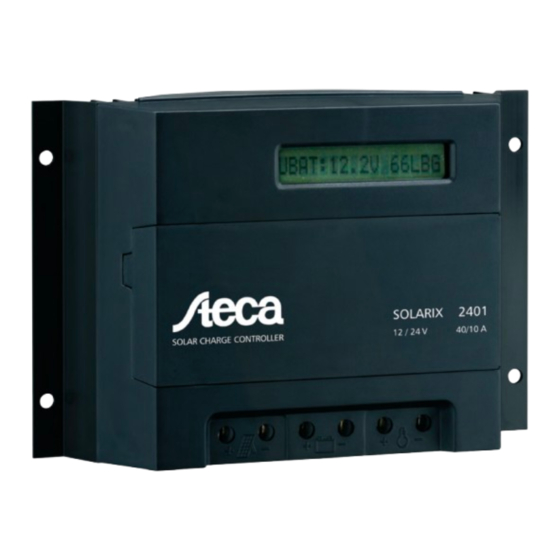
The solar charge controllers Steca Solarix 2401 and 4401 are
optimally suited for inverter systems. The controller combines
basic solar charger functions with a 40 A high-performance
charge controller. It is available as 12 V / 24 V and 48 V system.
This makes the solar charge controller very cost effective.
The load current is limited to 10 A. The charging processes
are based on the voltage level, which can be individually set
with the help of four buttons behind the front casing.
Product features
Hybrid controller
„
Voltage regulation
„
Automatic detection of voltage
„
PWM control
„
Multistage charging technology
„
Load disconnection depending on voltage
„
Automatic load reconnection
„
Temperature compensation
„
Common positive grounding or negative grounding on
„
one terminal
Integrated self test
„
Monthly maintenance charge
„
Electronic protection functions
Overcharge protection
„
Deep discharge protection
„
Reverse polarity protection of load, module and battery
„
Reverse polarity protection by internal fuse
„
Automatic electronic fuse
„
Short circuit protection of load and module
„
Overvoltage protection at module input
„
Open circuit protection without battery
„
Reverse current protection at night
„
Overtemperature and overload protection
„
Battery overvoltage shutdown
„
Displays
Text LCD display
„
for operating parameters, fault messages, self test
—
Operation
Simple menu-driven operation
„
Programming by buttons
„
Manual load switch
„
Interfaces
RJ45 interface
„
Options
External temperature sensor
„
Alarm contact
„
Certificates
Compliant with European Standards (CE)
„
Made in Germany
„
Developed in Germany
„
Manufactured according to ISO 9001 and ISO 14001
„
[ a r e a s o f a p p l i c a t i o n ]
[ 4 0 A ]
Characterisation of the operating performance
System voltage
Own consumption
DC input side
Module current
DC output side
Load current
End of charge voltage
Boost charge voltage
Equalisation charge
Reconnection voltage (LVR)
Deep discharge protection (LVD)
Operating conditions
Ambient temperature
Fitting and construction
Terminal (fine / single wire)
Degree of protection
Dimensions (X x Y x Z)
Weight
Technical data at 25 °C / 77 °F
1920 W
187
177
5
2401
4401
12 V (24 V)
48 V
14 mA
40 A
10 A
13.7 V (27.4 V)
54.8 V
14.4 V (28.8 V)
57.6 V
14.7 V (29.4 V)
58.8 V
12.6 V (25.2 V)
50.4 V
11.1 V (22.2 V)
44.4 V
-10 °C ... +60 °C
16 mm
/ 25 mm
- AWG 6 / 4
2
2
IP 32
187 x 128 x 49 mm
550 g
Steca PA TSK10
External temperature sensor
Advertisement
Table of Contents

Related Manuals for Steca Solarix 2401


Summary of Contents for Steca Solarix 2401
- Page 1 Steca Elektronik GmbH | 87700 Memmingen | Germany | Fon +49 (0) 8331 8558-0 | Fax +49 (0) 8331 8558-132 | www.steca.com Steca Solarix 2401, 4401 The solar charge controllers Steca Solarix 2401 and 4401 are optimally suited for inverter systems. The controller combines basic solar charger functions with a 40 A high-performance charge controller.
- Page 2 PHOTOVOLTAIK - PHOTOVOLTAIC - PHOTOVOLTAIQUE - FOTOVOLTAICA User- and Operation manual Specially designed for hybrid systems and telecommunications Steca Solarix 2401 - 4401 716.148 | Z02 | 09_45...
-
Page 3: Table Of Contents
Positive Grounding.................................. 14 6.7.2 Negative Grounding ................................14 Maintenance .................................14 Technical Data ..............................14 Performance Data..............................14 Controlling Data at 25°C ............................15 Malfunctions And Errors .............................15 Legal Guarantee..............................16 © Steca GmbH; Version 09_45; S.Nr. 716.148 System-Manager TAROM | 716148 page 2 V09_45A... -
Page 4: Safety Instructions And Waiver Of Liability
1 Safety Instructions And Waiver of Liability 1.1 Symbol of Safety Instructions Safety instructions for personal protection and instructions that refer to the safety functions of the system are marked with this sign and are printed in bold letters. For safe installation of other components which are not mentioned in the PV System-Manager instructions, please see the corresponding safety manual of the component manufacturer. -
Page 5: Waiver Of Liability
Keep children away from any and all electronics! Fatal accidents can occur! 1.4 Waiver Of Liability The manufacturer (STECA and its assigned representatives) cannot check that this manual is strictly followed, nor the conditions and methods for installation, operation, use and maintenance of the System-Manager. -
Page 6: Performance
2.1 Performance The System-Manager uses a heat sink (the black aluminium back plate) to dissipate heat produced by the electronics during high amperage charging. The System- Manager can be used in a wide range of conditions and temperatures. It automatically detects the maximum permissible temperature of the heat sink and disconnects... -
Page 7: Temperature Compensation Of Final Charge Voltage
3.1.2 Temperature Compensation Of Final Charge Voltage 2,55 As the battery temperature increases, the acid/lead battery’s optimal final load voltage decreases. A constant 15,0 2,50 final charge voltage leads to uncontrolled gassing in the case of higher battery temperatures, and 14,7 2,45 2,45... -
Page 8: Control Keyboard
3.1.7 Control Keyboard By using the tact switches underneath the LCD screen, the factory set values can be configured to the user’s custom requirement. Freely programmable values can only be changed within a pre-set window. These minimum-maximum values are selected in a way that even extreme adjustments do not lead to severe damage to the lead batteries. However, the operating elements are not protected or locked with a child-proof lock (code). -
Page 9: Operating The System-Manager
This window monitors also battery voltage (13,7) as well as charge current (+04.3) and the discharge current (-12.4) with more accurate values. 5 Operating The System-Manager 5.1 Safety Cover The safety cover is a plastic lid covering the programming keys and safety fuses. The lid can be removed if desired. In order to avoid undesired modification of important settings, however, it is recommended that the lid be left on the System- Manager. - Page 10 time. “auto“ automatically protects the battery from being deep discharged. possibilities for programming: load on, load off, auto Before this menu function is activated, it is necessary to disconnect the solar PV modules and all loads. Before Uninstalling (chapter 6.5, page 13) please refer to the related information. After having scrolled to this window, a self test can be started by pressing OK.
-
Page 11: Installation
6 Installation 6.1 Precautions Do not install any PV or electronic components in rooms where flammable gas mixtures may occur! Within the battery’s immediate surroundings, explosive gases may be generated. So please see that the battery room is adequately ventilated and avoid generating sparks. The following instructions for batteries must be adhered. -
Page 12: Installation On Walls
6.2.1 Installation On Walls The System-Manager has to be mounted on fire-proof surface. Furthermore, no flammable material should be allowed under the place where the System-Manager is mounted. The System-Manager is to be installed on vertical walls. This is the only way that the System-Manager can be cooled by naturally rising air (chimney effect) and work correctly. -
Page 13: Installation And Operation
modules will be free of voltage and current so the chances of damage to the System-Manager or injury to the installer is greatly reduced. • Solar modules must in no case be short circuited to zero out the voltage from the PV array! Spark development can damage wiring, connections, cause fire, or even damage electronics due to the high spikes of current! •... -
Page 14: Uninstalling
no longer controls these loads! Here user training and awareness is vital to protect the customer’s batteries from damage. Protect these direct loads by installation of safety fuses. Finally, secure all cables within the System-Manager’s immediate surrounding by strain reliefs. All other components must also have their wiring be strain-relieved. -
Page 15: Grounding
However, there are some double errors that may lead to the destruction of the System-Manager or components (consumer components, modules ), such as: • reverse polarity battery connection on the solar PV terminals • One battery wire on the module terminal, the other on the load terminal. •... -
Page 16: Controlling Data At 25°C
storage temperature -25°C...80°C Connecting screws 16/25mm² Weight 400g Dimensions 188x128x49mm Type of protection IP22 8.2 Controlling Data at 25°C 2401 4401 end of charge (float) voltage programmable 13,0V...14,5V 26;0V...29,0V 52,0V...58,0V Factory adjustment 13,7V 27,4V 54,8V Quick charging programmable 13,5V...15,0V 27;0V...30,0V 54,0V...60,0V boost charging Factory adjustment... -
Page 17: Legal Guarantee
current” Although this will not cause an immediate defect, the heat nominal currents. The system must sink will become very hot and could cause injury. The load be split into smaller PV arrays units is disconnected in order to avoid further self-heating. After on separate System-Managers. - Page 18 The seller must be informed before legal guarantee claims are processed. For processing a legal guarantee claim an exact fault description and the invoice / delivery note must be provided. The seller can choose to fulfil the legal guarantee either by repair or replacement. If the product can neither be repaired nor replaced, or if this does not occur within a suitable period in spite of the specification of an extension period in writing by the customer, the reduction in value caused by the fault shall be replaced, or, if this is not sufficient taking the interests of the end customer into consideration, the contract is cancelled.
- Page 21 716148...
Need help?
Do you have a question about the Solarix 2401 and is the answer not in the manual?
Questions and answers