
Related Manuals for Lowara e-HM series


Summary of Contents for Lowara e-HM series
- Page 1 Installation, Operation and Maintenance Manual e-HM Series Multistage Horizontal Pump Unit...
-
Page 3: Table Of Contents
4.4 Electrical connection......................20 4.4.1 Ground......................... 20 4.4.2 Guidelines for electrical connection................ 20 4.4.3 Guidelines for the electric panel................20 4.4.4 Motor guidelines......................21 4.4.5 Operation with frequency converter................22 5 Operation..........................23 5.1 Precautions......................... 23 e-HM Series Installation, Operation and Maintenance Manual... - Page 4 8.8 Noise level.......................... 35 8.9 Materials..........................36 9 Disposal............................. 37 9.1 Precautions......................... 37 10 Declarations..........................38 10.1 EC Declaration of Conformity (Original)...............38 10.2 EU Conformity Declaration (n. EMCD08)..............38 11 Warranty..........................39 11.1 Information........................39 e-HM Series Installation, Operation and Maintenance Manual...
-
Page 5: Introduction And Safety
It identifies a dangerous situation which, if not avoided, CAUTION: may cause small or medium level injuries. It identifies a situation which, if not avoided, may cause NOTICE: damage to property but not to people. e-HM Series Installation, Operation and Maintenance Manual... -
Page 6: User Safety
Disposal of packaging and product Comply with the current regulations on sorted waste disposal. Leaking of fluid If the unit contains lubricating fluid, take appropriate measures to prevent the dispersion of leaks into the environment. e-HM Series Installation, Operation and Maintenance Manual... -
Page 7: Sites Exposed To Ionizing Radiations
If the unit has been exposed to ionizing radiations, implement the necessary safety measures for the protection of people. If the unit needs to be despatched, inform the carrier and the recipient accordingly, so that appropriate safety measures can be put in place. e-HM Series Installation, Operation and Maintenance Manual... -
Page 8: Transport And Storage
2. A cardboard box with wooden base. The type 2 packaging is intended for transport with a forklift truck; the lifting points are indicated in the figure. Figure 1: Packed product lifting points e-HM Series Installation, Operation and Maintenance Manual... -
Page 9: Unit Inspection Upon Delivery
Use cranes, ropes, lifting straps, hooks and clasps that comply with current regulations and that are suitable for the specific use. NOTICE: Make sure that the harnessing does not hit and/or damage the unit. e-HM Series Installation, Operation and Maintenance Manual... -
Page 10: Storage
Figure 3: Drain plug For further information about preparation for long-term storage, please contact Xylem or the Authorised Distributor. e-HM Series Installation, Operation and Maintenance Manual... -
Page 11: Product Description
Maximum temperature of pumped liquid (for usage in compliance with EN 60335-2-41) Maximum ambient operating temperature Maximum operating pressure Minimum head Weight Electrical data Maximum temperature of pumped liquid (for usage outside the scope of EN 60335-2-41) e-HM Series Installation, Operation and Maintenance Manual... - Page 12 V = Aluminum oxide (ceramic) Mechanical seal Q = Silicon carbide(Q1) fixed part B = Resin impregnated carbon For uses outside the scope of EN 60335-2-41 For uses outside the scope of EN 60335-2-41 e-HM Series Installation, Operation and Maintenance Manual...
-
Page 13: Marks Of Safety Approval
The presence of an electric safety approval mark, for example IMQ, TUV, IRAM, only refers to the pump unit. In case of no further special configuration characters on the right, this character will be nil, otherwise it will be “X” e-HM Series Installation, Operation and Maintenance Manual... -
Page 14: Denomination Of The Main Components
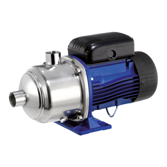
Figure 6: Pump unit with close-coupled body Position Description Position Description number number Pump body Elastomers Impeller Filling plug Diffuser Wear ring Pump shaft Drain plug Motor adapter Motor Seal housing Suction port Mechanical seal Discharge port e-HM Series Installation, Operation and Maintenance Manual... -
Page 15: Intended Use
• Circulation of hot and cold liquids, for example water or water & glycol, for heating, cooling and air conditioning systems • Water treatment applications • Handling of moderately aggressive liquids. 3.4.1 Pumped liquids • Hot water • Cold water e-HM Series Installation, Operation and Maintenance Manual... -
Page 16: Improper Use
It is prohibited to pump drinking water after use with other fluids. WARNING: Take appropriate measures during transport, installation and storage to prevent contamination from external substances. WARNING: Remove the unit from its packaging just before installation to prevent contamination from external substances. e-HM Series Installation, Operation and Maintenance Manual... - Page 17 3 Product Description WARNING: After installation, run the unit for a few minutes with several users open in order to wash the inside of the system. e-HM Series Installation, Operation and Maintenance Manual...
-
Page 18: Installation
Air clearance between a wall and the motor fan grille • To ensure suitable ventilation: ≥ 100 mm. • To permit inspection and removal of the motor: ≥ 300 mm. If the space available is any less, refer to the technical catalogue. e-HM Series Installation, Operation and Maintenance Manual... -
Page 19: Permitted Positions
4.2.4 Reducing vibrations The motor and the flow of liquids in the pipes may cause vibrations, which can be exacerbated by incorrect installation of the unit and pipes. See Hydraulic connection page 18. e-HM Series Installation, Operation and Maintenance Manual... -
Page 20: Hydraulic Connection
Install appropriate seals between the unit couplings and the pipings. 4.3.1 Guidelines for the hydraulic system Refer to the representative hydraulic diagrams; see the figures below. Figure 10: Positive suction head installation diagram Figure 11: Suction lift installation diagram e-HM Series Installation, Operation and Maintenance Manual... - Page 21 12.In case of suction lift installation, the suction pipe must have an increasing slope towards the unit exceeding 2%; to avoid air pockets; also install: e-HM Series Installation, Operation and Maintenance Manual...
-
Page 22: Electrical Connection
– A mains isolator switch with a contact gap of at least 3 mm. 4.4.3 Guidelines for the electric panel NOTICE: The electric panel must match the ratings on the unit data plate. Improper combinations could damage the motor. e-HM Series Installation, Operation and Maintenance Manual... -
Page 23: Motor Guidelines
(motor start-up), or thermal magnetic switch with C curve and Icn ≥ 4.5 kA, or other similar device Trip class 10 A overload thermal relay + aM fuses (motor starting), or start class 10 A motor protection thermal magnetic switch e-HM Series Installation, Operation and Maintenance Manual... -
Page 24: Operation With Frequency Converter
90R (500 V) > 650 > 2200 from 90R to 180R > 1400 > 4600 over 180R > 1600 > 5200 Otherwise, use a motor with reinforced insulation and a sinusoidal filter. Available on request e-HM Series Installation, Operation and Maintenance Manual... -
Page 25: Operation
NOTICE: It is prohibited to use the unit in the case of cavitation. NOTICE: The unit must be filled and vented properly before it can be started. e-HM Series Installation, Operation and Maintenance Manual... -
Page 26: Filling - Priming
4. Wait a few minutes and top up with more liquid if necessary. 5. Remove any air that might be present through the relief valve of the suction pipes (see Guidelines for the hydraulic system on page 18). 6. Replace the plug (B). e-HM Series Installation, Operation and Maintenance Manual... -
Page 27: Checking The Direction Of Rotation (Three-Phase Motors)
3. Connect the power supply. 4. Start the pump unit. 5. Check the direction of rotation through the coupling protection, or through the motor fan cover 6. Stop the pump unit. e-HM Series Installation, Operation and Maintenance Manual... -
Page 28: Start-Up
1. Close and open the on-off valve on the discharge line two or three times with the unit running. 2. Stop and start the unit two or three times. e-HM Series Installation, Operation and Maintenance Manual... -
Page 29: Stopping
1. Shut the on-off valve located on the discharge line. 2. Stop the pump unit and check that the motor slows down gradually. 3. Gradually re-open the on/off valve and check that the motor remains still. e-HM Series Installation, Operation and Maintenance Manual... -
Page 30: Maintenance
500 Vdc for 1 minute. 6. Check the terminal board of the motor for any signs of overheating and arc flashes. 7. Check the condition of the motor's cooling fan and clean it. e-HM Series Installation, Operation and Maintenance Manual... -
Page 31: Long Periods Of Inactivity
4. Before restarting the unit, check that the shaft is rotating freely, without mechanical impediments. 6.4 Ordering spare parts Identify the spare parts with the product codes directly on the site www.lowara.com/spark. Contact Xylem or the Authorised Distributor for technical information. e-HM Series Installation, Operation and Maintenance Manual... -
Page 32: Troubleshooting
Tighten or replace the clamps and terminals protection Loose and/or incorrect and/or faulty (star-delta) Tighten or replace the clamps and terminals connections in the terminal board of the motor Motor (coil) faulty Check and repair or replace the motor e-HM Series Installation, Operation and Maintenance Manual... -
Page 33: The Thermal Motor Protection Trips
Foot check valve faulty Replace the foot check valve 7.8 The unit produces excessive noise and/or vibrations Cause Remedy Cavitation Increase the NPSH available in the system Net Positive Suction Head Net Positive Suction Head e-HM Series Installation, Operation and Maintenance Manual... -
Page 34: The Unit Starts Up Too Frequently (Automatic Start/Stop)
Replace the mechanical seal with another of a suitable liquid outside the rated limits make Mechanical seal damaged due to chemical Replace the mechanical seal with a model chemically incompatibility with the liquid compatible with the pumped liquid e-HM Series Installation, Operation and Maintenance Manual... -
Page 35: The Motor Becomes Excessively Hot
The frequency converter, if present, has not been See the frequency converter manual calibrated properly 7.13 The frequency converter (if present) is in error mode or turned Cause Remedy See the frequency converter manual See the frequency converter manual e-HM Series Installation, Operation and Maintenance Manual... -
Page 36: Technical References
0.95 0.95 0.90 0.85 0.80 0.76 8.2 Temperature of pumped liquid The pressure-temperature diagram in the figure shows the operating limits of the unit. Contact Xylem or the Authorised Distributor for special needs. e-HM Series Installation, Operation and Maintenance Manual... -
Page 37: Operating Pressure
380/660 ± 10 No. of conductors + earth 8.8 Noise level The free field LA sound pressure level measured at a distance of one metre from the unit is less than 70 dB (A). e-HM Series Installation, Operation and Maintenance Manual... -
Page 38: Materials
Material Pump body Impellers Diffusers HM..P Stainless steel/AISI 304 Technopolymer Stainless steel/AISI 304 HM..S Stainless steel/AISI 304 Stainless steel/AISI 304 Stainless steel/AISI 304 HM..N Stainless steel/AISI 316 Stainless steel/AISI 316 Stainless steel/AISI 316 e-HM Series Installation, Operation and Maintenance Manual... -
Page 39: Disposal
The unit must be disposed of through approved companies specialised in the identification of different types of materials (steel, copper, plastic, etc.) WARNING: It is prohibited to dispose of lubricating fluids and other hazardous substances in the environment. e-HM Series Installation, Operation and Maintenance Manual... -
Page 40: Declarations
Signed for and on behalf of: Xylem Service Italia S.r.l. Montecchio Maggiore, 11.03.2016 Amedeo Valente (Director of Engineering and R&D) rev.00 Lowara is a trademark of Xylem Inc. or one of its subsidiaries. e-HM Series Installation, Operation and Maintenance Manual... -
Page 41: Warranty
11 Warranty 11 Warranty 11.1 Information For information on the warranty refer to the documentation of the sale contract. e-HM Series Installation, Operation and Maintenance Manual... - Page 44 Xylem |’zīləm| 1) The tissue in plants that brings water upward from the roots; 2) a leading global water technology company. We’re a global team unified in a common purpose: creating advanced technology solutions to the world’s water challenges. Developing new technologies that will improve the way water is used, conserved, and re-used in the future is central to our work.
Need help?
Do you have a question about the e-HM series and is the answer not in the manual?
Questions and answers