
Subscribe to Our Youtube Channel
Related Manuals for Sony DXC-327BK


Summary of Contents for Sony DXC-327BK
- Page 1 3-856-085-22(1) Color Video Camera Operating Instructions Before operating the unit, please read this manual thoroughly and retain it for future reference. DXC-327BK/BL/BH/BF DXC-327BPK/BPL/BPH/BPF © 1996 by Sony Corporation...
- Page 2 Owner’s Record The model and serial numbers are located on the right side. Record these numbers in the spaces provided below. Refer to them whenever you call your Sony dealer regarding this product. Model No. Serial No.
-
Page 3: Table Of Contents
Table of Contents Introduction .............. 4 Adjustment and Settings ........46 Composition of the DXC-327B-series Color Reading Indications in the Electronic Video Camera ........... 4 Viewfinder ..........46 Choosing from NTSC or PAL System ....5 Reading the Viewfinder Screen Display Menu . 49 Notes on Using Accessories with the DXC-327B Adjusting the Viewfinder Screen Display .. -
Page 4: Introduction
VCL-714BX zoom lens DXC-327BH/327BPH Chart for flange focal length adjustment DXC-327B/327BP camera head LC-421 carrying case Composition Model DXC-327BK/327BPK DXC-327BL/327BPL DXC-327BH/327BPH DXC-327BF/327BPF DXC-327B/327BP camera head VCL-714BX zoom lens DXF-601/601CE viewfinder LC-421 carrying case VCT-U14 tripod attachment Chart for flange focal length adjustment... -
Page 5: Choosing From Ntsc Or Pal System
Notes on Using Accessories with Choosing from NTSC or PAL the DXC-327B Series Camera System • If you use the CA-537/537P Camera Adaptor (not The following explains the differences between the supplied) with this camera, operate the camera NTSC and PAL system regarding accessory selection according to the instructions in this manual. -
Page 6: Precautions
• Do not use any type of solvent, such as alcohol or benzine which might damage the finish. If you have any questions about this camera, contact your authorized Sony dealer. -
Page 7: Features
Features ™ Power HAD Sensor CCD Chip design Viewfinder displays The Power HAD ™ Sensor CCD Chip design employs So you don’t have to take your eye off what you are three -inch CCD (Charge Coupled Device) images shooting, the viewfinder displays adjustment each having a total of about 380,000 (NTSC) or indications and warning. -
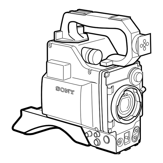
Page 8: Location And Function Of Parts
Location and Function of Parts DXC-327B/327BP Camera Head The DXC-327B/327BP Camera Head is the modular units to it via the CA-537/537P or CA-327/327P core of this multipurpose camera system. Depending Camera Adaptor. on your purpose, connect VTRs and camera control Camera head power supply and indications IT E B A L... - Page 9 1 POWER switch 3 VF MARKER (viewfinder safety zone marker OFF: Turns the camera off. and/or center marker) selector ON SAVE: Select to save power. When you press the Use this selector to display the safety zone marker and/ VTR start button, there is a delay before recording or center marker on the viewfinder screen.
- Page 10 Location and Function of Parts Camera head attachments and input/output connectors Accessory shoe Light receptacle Handle Viewfinder attachment Built-in microphone PRO 50-pin connector Microphone holder attachment !¡ Lens mount !™ Cord clamps L E N S V ID E O U T !£...
- Page 11 5 PRO 50-pin connector !¡ Lens mount Connect to the 50-pin connector of the camera adaptor Attach the VCL-714BX Zoom Lens or another " or EVV-9000/9000P, PVV-1/1P/1A/1AP/3/3P. (See lens and related equipment here. pages 22 to 24.) !™ Cord clamps 6 Microphone holder attachment Secure the viewfinder cord.
- Page 12 Location and Function of Parts Camera head switches and controls !¶ FILTER selector !• IT E AUTO W/B BAL switch B A L !ª UP/ON and DOWN/OFF buttons @º WHITE BAL selector Inside the lid @¡ ABL switch @™ SC PHASE control @£...
- Page 13 !¶ FILTER selector @º WHITE BAL (white balance memory) selector A or B: Select A or B to make the camera use the Selects the appropriate filter according to lighting white balance setting stored in memory position A conditions. or B. PRE: Set to PRE when there is no time to adjust the Filter number Color temperature Lighting conditions white balance.
- Page 14 Location and Function of Parts Camera head output selectors @∞ VTR button IT E B A L @§ GAIN selector Inside the lid @¶ SHUTTER switch @• BARS switch @ª REC REVIEW button...
- Page 15 @∞ VTR button @• BARS (color bar generation) switch When connecting the camera to a portable VTR, press ON: Set to this position to display the color bars on this button to start and stop recording. the viewfinder or video monitor screen when When connecting the camera to a CCU-M7/M7P or adjusting its contrast and brightness.
-
Page 16: Ca-537/537P Camera Adaptor (Optional)
Location and Function of Parts CA-537/537P Camera Adaptor (optional) DC IN connector Battery case MIC POWER switch EARPHONE jack VTR SELECT switch MIC IN connector PRO 50-pin connector !£ MIC LEVEL switch !¡ VTR START/RETURN VIDEO button !™ INTERCOM volume control INTERCOM connector VTR/CCU/CMA connector GEN LOCK IN connector... - Page 17 8 VTR/CCU/CMA connector (26-pin) Power supply Connect a VTR, CCU-M7/M7P or CCU-M5/M5P Camera Control Unit or CMA-8A/8ACE Camera 1 DC IN (input) connector (XLR-4 pin) Adaptor here. Connect an external DC power source (12 volt DC) here to supply power to the camera adaptor and 9 GEN LOCK IN (gen-lock input) connector camera.
-
Page 18: Vcl-714Bx Zoom Lens
Location and Function of Parts VCL-714BX Zoom Lens ZOOM selector Manual zoom lever Focus ring Iris ring Ff adjustment ring MACRO ring and button Lens hood Focus remote control connector Zoom remote control connector IRIS selector Instant automatic iris !™ RET button adjustment button !¡... - Page 19 0 Zoom remote control connector (8-pin) Focusing To do remote control zoom when the camera is attached to a tripod, connect an LO-23 Lens Remote 1 Focus ring Control Unit (optional) here. To focus, turn this ring. !¡ Motorized zoom switch 2 Ff (flange focal length) adjustment ring For motorized zoom action, set the zoom selector to S.
-
Page 20: Dxf-601/601Ce Electronic Viewfinder
Location and Function of Parts DXF-601/601CE Electronic Viewfinder REC/TALLY BATT REC/TALLY indicator BATT indicator GAIN UP indicator SHUTTER indicator SHUTTER GAIN UP Eyepiece focusing knob Accessory fixing screw hole Tally lamp Eye cup Eyepiece release catch BRIGHT control CONTRAST control !¡... - Page 21 1 REC/TALLY (recording/tally) indicator (red) 8 Eyepiece release catch • From the time when you press the VTR button on the To view the viewfinder screen directly, press this lens or camera head, this flashes until recording catch, and hinge up the eyepiece. starts, then stays on continuously during recording.
-
Page 22: Accessory Attachment
VTR using as interface the that unit. Refer to the below procedure to attach the optional Sony CA-537/537P or CA-327/327P Camera CA-537/537P Camera Adaptor. Attaching the CA-537/537P camera adaptor... - Page 23 Tighten the two screws at the bottom of the shoulder pad. Screws Detaching the camera adaptor To detach the camera adaptor, reverse the order of the above procedure. Note on connection with the CA-327/327P camera adaptor You can connect the following CA-327/327P series camera adaptors to the DXC-327B/327BP: CA-327: Serial No.
-
Page 24: Attaching A Videocassette Recorder
Accessory Attachment Attaching a Videocassette Recorder To attach an EVV-9000/9000P Hi8 Format To attach a Betacam format video cassette recorder Videocassette Recorder to the camera head, follow the such as a PVV-1/1P/1A/1AP/3/3P, follow the procedures for attaching and detaching the CA-537/ procedure below. -
Page 25: Attaching The Zoom Lens And Optional Filter
Attaching the Zoom Lens and Optional Filter Check that the zoom lens you are going to mount is Preparations -inch lens. Remove the protective caps from the mounts of the Caution camera and the lens. -inch lens cannot be directly attached to the lens mount of the video camera. - Page 26 Accessory Attachment Attaching the zoom lens Turn the mount clamp lever fully counter clockwise to align the lens notch and the red Red point point. Notch Align the center pin in the lens with the notch in the lens mount, and insert the lens into the mount.
-
Page 27: Attaching And Adjusting The Electronic Viewfinder
Attaching and Adjusting the Electronic Viewfinder Loosen the lock ring. Align and guide the viewfinder along Lock ring the mount. To detach the viewfinder, loosen the lock ring. Then while pulling up the pin, slide the viewfinder off the mount. Turn and tighten the lock ring to fix the viewfinder. - Page 28 Accessory Attachment Adjusting to the left or right Loosen the lock ring. Looking through the eyepiece, 1, 3 slide the viewfinder sideways to the most convenient position. Tighten the lock ring when the viewfinder is in a comfortable position. Adjusting the angle Storing the unit in the carrying case Always store the unit with the eye cup positioned downward, the viewfinder positioned as close to the...
-
Page 29: Attaching A Microphone
Attaching a Microphone In order to attach an ECM-670/672 External Note Microphone (optional), first fit a CAC-12 Microphone The ECM-670 should be used with a VTR or adaptor Holder (optional) to the camera head. which has the phantom-powering function. Remove the two screws from the side of the camera head. - Page 30 Accessory Attachment Insert the microphone in the microphone holder, close the holder and tighten the microphone holder bolt. Microphone When using a bayonet (thin) type microphone, attach a microphone adaptor to the microphone. When the ECM-670 is used, attach an adaptor supplied with the ECM-670.
-
Page 31: Attaching/Detaching A Tripod
Attaching/Detaching a Tripod Attaching the camera to the tripod Detaching the camera from the tripod First attach the VCT-U14 Tripod Adaptor to the tripod, then mount the camera on the tripod adaptor. Hold down the red button and pull the lever in the Slide the camera direction of the arrow. -
Page 32: Connections
Connections Make sure the power switches on the camera, VTR, Consult the “Differences in functions” on page 38 for and other equipment are set to OFF. details on the functions available with different VTRs. Attach the CA-537/537P Camera Adaptor to the For the general use of the camera with a VTR attached, camera head before attaching any of the below see “Basic Operations”... -
Page 33: Connecting A Portable Vtr
The camera cable can be extended up to 10 meters (33 feet) long. Consult your authorized Sony dealer. Connecting an External Microphone To avoid recording noise made while handling the With the below connections, note that the built-in camera, connect an external microphone to the MIC IN microphone automatically shuts off. -
Page 34: Connecting A Table-Top Vtr
DXC-327B/327BP The camera cable can be extended up to 300 m (990 feet) using the CCZZ-1B or CCZZ-1E Cable Extension Adaptor. Consult your authorized Sony dealer. CCU-M7/M7P do not affect the video output signal of Gamma and knee controls with the CCU-M7/ the camera. - Page 35 Notes on use with the CCU-M7/M7P or CCU-M5/M5P camera control unit Switch setting • Set the VTR SELECT switch on the camera adaptor to "1." • When the camera is connected to the CCU, the following switches on the camera head do not operate: GAIN selector WHITE BAL selector...
-
Page 36: Connecting A Remote Control Unit
Connecting a Remote Control Unit By connecting an RM-M7G Remote Control Unit (optional), you can control the principal camera functions at a distance. For more details on using the remote control, consult your Sony dealer. DXC-327B/327BP CCA-7-5/25/50/100 camera remote control cable... -
Page 37: Using The Camera With A Vtr
VTR adaptor for and the functions of the camera and the VTR vary. to the camera the VTR (Please consult your local authorized Sony dealer if VO-8800/ CCZQ-nA you want to use a VTR other than those shown in the 8800PS table below.) - Page 38 Connections Differences in functions Available functions differs depending on the VTR connected as shown below. Remote REC/TALLY indicator BATT Audio Picture shown on the viewfinder Connected control alarm monitor During recording During playback of VTR indication (on the (picture from (picture from start/stop indication alarm...
-
Page 39: Power Sources
Power Sources When the CA-537/537P Camera Adaptor is attached, the DXC-327B/327BP camera is powered by one of three types of power supply: external DC, battery DC, or AC power. Using a DC Power Supply Connecting to a DC power outlet Connect a connecting cable from the DC IN connector on the camera adaptor or on a VTR to the external power source of 12 V DC. -
Page 40: Using A Battery Pack
Power Sources Using a Battery Pack Before using the battery pack, recharge the battery (see “Charging the battery” on the next page). Installing the battery pack Press the button at the side of Camera adaptor the battery case lid and pull Press the button. - Page 41 Continuous battery operation time When a camera adaptor is attached, the fully charged battery pack can continuously power the camera and viewfinder for a certain amount of time (see the table below). However, with the EVV-9000/9000P Videocassette Recorder attached, battery life is shortened.
-
Page 42: Using Power Supplied Through The Camera Adaptor
Power Sources Using Power Supplied Through Using a CMA-8A/8ACE camera adaptor the Camera Adaptor Connect the CMA-8A/8ACE Camera Adaptor and the VTR/CCU/CMA connector on the camera adaptor To use the following equipment, make sure you have using the optional camera cable. Then the power is attached a CA-537/537P Camera Adaptor. -
Page 43: Basic Operations
Basic Operations The following is the basic procedure for operating the camera. To get the most out of the videotaping operation, we recommend you do the adjustments and settings on the following pages. Operating the Camera VTR SELECT switch ABL switch WHITE BAL selector GAIN selector Check that equipment connections, such as to the... -
Page 44: Recording With A Portable Vtr
Basic Operations Recording with a Portable VTR Recording with a Table-Top VTR Turn the power switches to the camera and To record using a table-top VTR, follow the procedure connected equipment to the ON position. explained for recording with a portable VTR except for the following: Set the VTR to Record Standby mode. -
Page 45: Monitoring The Vtr Picture And Audio Output
A playback picture (during playback) Monitoring the VTR Picture and Audio Output You can see the following three types of images on the viewfinder screen when the camera and the VTR are connected with the CCZQ camera cable. Note, however, that with some types of VTRs, you may not be able to monitor a picture. -
Page 46: Adjustment And Settings
Adjustment and Settings In the electronic viewfinder, the viewfinder screen itself shows you the settings of switches such as black/ white balance and gain. At the periphery of the screen the viewfinder indicators show the status of operations such as battery level. Reading Indications in the Electronic Viewfinder Viewfinder screen and status indicators... - Page 47 Reading warning indications on the When the camera is used with the PVV-3/ viewfinder display Two indications, “LOW LIGHT” and “BATT 10.7V” The data of the PVV-3/3P such as time code, user's bit, appear on the viewfinder screen. The following tape counter, etc.
- Page 48 Adjustment and Settings Current settings The viewfinder screen shows you the settings of the Press the DISP CHG switch several times until the switches on the camera head, camera adaptor, and following (see illustration below) display appears on zoom lens. If necessary, change the settings using the the viewfinder screen.
-
Page 49: Reading The Viewfinder Screen Display Menu
Reading the Viewfinder Screen Display Menu The following chart shows how the display changes on The display mode changes to the black balance or the screen each time you press the DISP CHG switch. white balance adjustment mode during adjustment and In all modes, the black balance and white balance can returns to the selected display after the adjustment is be adjusted automatically. -
Page 50: Adjusting The Viewfinder Screen Display
Turn the diopter ring (see illustration above) within the range of –0D to –3D until the view is clear. The adjustable range can be changed to that of –2 to +1 D or –0.5 to +3D. Consult your Sony dealer. -
Page 51: Adjusting The Video Monitor
Adjusting the Video Monitor When you are using a color video monitor to monitor the video output, adjust the color on the monitor using the procedure that follows. (See the section, “Connecting an S-VHS Format Portable VTR” on page 32 for information on how to connect a video monitor and a VTR.) Set the BARS switch to ON. -
Page 52: Adjusting The Iris
Adjustment and Settings Adjusting the Iris Instant automatic iris adjustment button IRIS selector Iris ring Temporary automatic adjustment Automatic iris adjustment To automatically adjust the iris while the IRIS Set the IRIS selector to “A.” This is the normal setting selector is set to “M”, keep the Instant Automatic for the automatic iris. - Page 53 Selecting the automatic iris reference level The selectable values are as follows: When adjusting the video level of a back-lit subject, • –1.0 you can change the automatic iris reference level setting. When you make the setting, it is retained in •...
-
Page 54: Selecting The Filter
Adjustment and Settings Selecting the Filter Adjusting the Black Balance The color temperature changes according to lighting Adjust the black balance to ensure picture clarity and conditions. To compensate for this, use one of the life-like color reproduction. color temperature conversion filters indicated in the When adjusting the black balance, the black set is table below. - Page 55 Adjusting black balance Re-adjust the black balance The adjusted value is stored on the camera, and is kept even when the power is turned off. Normally readjustment is not required except for the following cases. • “MEMORY NG” appears on the viewfinder screen. •...
-
Page 56: Adjusting The White Balance
Adjustment and Settings Adjusting the White Balance The white balance should be adjusted so that a white store the adjusted white balance values. You can store object is reproduced as white and life-like color is two adjusted values under two different lighting obtained. - Page 57 When the white balance cannot be When you have no time to adjust the white adjusted automatically balance The following characters appear on the screen display Select the appropriate filter with the FILTER if white balance cannot be adjusted automatically. Re- selector on the camera depending on the lighting adjust the white balance after taking the measures conditions.
-
Page 58: Adjusting The Contrast
Adjustment and Settings Adjusting the Contrast To adjust the contrast, change the pedestal level. change the level from about –30% to +30% of When the master pedestal level is raised, the dark reference level (0.7 V) in increments of 1%. The portion of the picture brightens, and when the level is adjusted master pedestal level is kept in the memory of lowered, the corresponding portion darkens. -
Page 59: Selecting The Shutter Speed
Selecting the Shutter Speed The shutter speed is factory set to 1/100 for NTSC and 1/60 for PAL. You can change the shutter speed if necessary. Select the shutter speed from the following: For NTSC: 1/100, 1/250, 1/500, 1/1000, 1/2000 For PAL: 1/60 , 1/250, 1/500, 1/1000, 1/2000. -
Page 60: Advanced Operations
Advanced Operations Manual zoom Zoom Operation Manual zoom allows more precise control over the You can go from wide angle to telephoto shots by zooming speed. using the motorized zoom or doing the zoom manually. Motorized zoom Zooming at a constant speed is obtained. Wide angle Telephoto Wide angle Telephoto... -
Page 61: Adjusting Flange Focal Length
Adjusting Flange Focal Length The proper flange focal length adjustment ensures that the object is in focus both at the wide-angle and telephoto position when using the zoom. Once you have made the flange focal length adjustment, you do not have to re-adjust the lens as long as the lens stays on the same camera. -
Page 62: Doing Close-Ups
Advanced Operations Doing Close-Ups The close-up or macro function lets you zoom in flowers, insects and even photographs. The minimum distance from the lens to the object is 10 mm in the 7.5 wide-angle zoom position. To reduce the object size on the screen Adjust the distance between the lens and the object to get the desired image size. -
Page 63: Adjusting The Sharpness Of The Picture
Adjusting the Sharpness of the Picture You can increase (harden) or decrease (soften) the sharpness of the picture. Change the value of the detail level to increase or decrease the sharpness. The detail level can be set from –99 to +99 of the factory-set reference level (00). -
Page 64: Selecting The Output Level
Advanced Operations Selecting the Output Level Checking the Video Level If you cannot get a clear picture because of insufficient Use the zebra pattern (generated by the camera) as a reference when adjusting the iris manually. The zebra light, set the GAIN selector to a higher or lower pattern indicates areas of the picture where the video position. -
Page 65: Synchronizing Two Or More Cameras (Without Using A Camera Control Unit)
Synchronizing Two or More Cameras (Without Using a Camera Control Unit) When a BS or VBS signal is connected to the GEN LOCK IN connector on the camera adaptor, the camera synchronizes with the connected signal. Use the GEN LOCK IN connector when you are using two or more cameras without a camera control unit. - Page 66 Advanced Operations Adjustment of the picture tone for two or more cameras When two or more cameras are used simultaneously in connection with a special-effects generator, supply each camera with the same reference signal and adjust each camera to get the same picture tone. Adjust the SC (subcarrier) phase and the H (horizontal) phase following the procedures described below.
-
Page 67: Title Characters Setting
Title Characters Setting This camera contains a built-in character generator that allows you to superimpose characters over the picture being shot. Both the picture and the superimposed characters appear on the monitor screen. If a recording VTR is connected to the camera, the superimposed characters can be recorded on the VTR. - Page 68 Advanced Operations Setting title characters Setting procedure Set title characters one by one choosing them from the display using the UP/ON and DOWN/OFF buttons. Up to 12 characters can display on one line. Up to 4 lines can be displayed. Title characters, once set, remain in the memory of the camera, and are not erased when the power is turned off.
- Page 69 To replace a character The next time you use the camera Return the cursor to the position of the character you want to replace, select the desired character with the When you turn on the camera, the memorized UP/ON button, and press the DOWN/OFF button. The characters are displayed on the viewfinder screen at characters must be changed one by one as described in step 1 of “Preparation”...
-
Page 70: Connecting A Number Of Cameras (Using A Camera Control Unit)
Advanced Operations Connecting a Number of Cameras (Using a Camera Control Unit) When using a number of cameras in the studio, it may In the studio it may also be convenient to use a DXF- 40B/40BCE/50B/B0BCE Viewfinder. be necessary to use a CCU-M5/M5P/M7/M7P Camera The figure below shows an example studio Control Unit to provide video and color sync between cameras, and special effects and other devices to allow... -
Page 71: Using The Optional Carrying Case
Using the Optional Carrying Case Storing the Camera Align the camera with the base of the case, and slide Align the camera with the base of the carry case. the camera in forward. Checking that the pin at the rear engages correclty, push forward until it locks into place. -
Page 72: Specifications
Specifications Signal to noise ratio Camera Head DXC-327B/327BP 63 dB (NTSC, Typical) 61 dB (PAL, Typical) Image device Interline-transfer CCD, 3-chip Registration 0.05% for all zone Effective picture elements (without lens) 768 × 494 (h/v) (NTSC) Inputs/Outputs VIDEO OUT: BNC-type, 752 ×... -
Page 73: Camera Adaptor
Focal length 7.5 mm to 105 mm VCL-714BX zoom lens (supplied with Zoom Manual and motorized, selectable the DXC-327BK/327BPK/327BF/327BPF only) (1) Zooming ratio: 14× DXF-601/601CE electronic viewfinder (supplied with Maximum aperture ratio the DXC-327BK/327BPK/327BL/327BPL/327BF/ 1:1.4 (7.5 to 75 mm) to 1:1.8 (105... -
Page 74: Optional Accessories And Recommended Equipment
Optional Accessories and Recommended Equipment Lens and Accessories Camera Cable and Others Zoom lens: VCL-714BX Camera cable with Z-type 26 pin connectors: Lens remote control unit: LO-23 CCZ-A2, CCZ-A5, CCZ-A10 Tripod attachment: VCT-U14 CCZ-A25, CCZ-A50, CCZ-A100 Camera cable with Z-type 26 pin and Q-type Camera Adaptor 14 pin connectors: CCZQ-A2, CCZQ-A5, Camera adaptor: CA-537/537P, CA-327/327P,... -
Page 75: Sample Video System Configuration
Sample Video System Configuration (Combined use with a dockable VTR) EVV-9000/9000P video cassette recorder BVW-35/35P/50/50P portable video cassette recorder NP-1B battery pack CA-537/537P CCU-M7/M7P/M5/M5P camera adaptor camera control unit ECM-672 microphone DXF-601/601CE viewfinder CAC-12 microphone SVO-5800/5800P LO-23 holder S-VHS format VTR lens remote control unit NP-1B... -
Page 76: Glossary
Glossary Black set Return video Black set means that the R, G and B signals of a video The “return video” is the picture from a VTR during signal are set to the memorized level to obtain the recording, the playback picture during playback, or the definite black level for each R, G and B signals. -
Page 77: Index
Index Standby 9 Sub-carrier phase (SC PHASE) Accessories 4 GAIN UP indicator 21, 46 adjustment 13, 66 usable with DXC-327B/327BP- Gain 15, 63 Synchronizing, without camera control series 5 unit 65 Aliasing 6 with special-effects generator 70 HAD sensor 7 Horizontal phase (H PHASE) adjustment BATT indicator 21, 46 13, 66... - Page 80 Sony Corporation Printed in Japan...
Need help?
Do you have a question about the DXC-327BK and is the answer not in the manual?
Questions and answers