Table of Contents
Advertisement
Quick Links
Advertisement
Table of Contents

Subscribe to Our Youtube Channel
Related Manuals for Sony DXC-D30P


Summary of Contents for Sony DXC-D30P
- Page 1 DIGITAL VIDEO CAMERA DXC-D30/D30P SERVICE MANUAL Vol. 1 (1st Edition/Revised 1)
- Page 2 CAUTION ADVARSEL Danger of explosion if battery is incorrectly Lithiumbatteri - Eksplosjonsfare. replaced. Ved utskifting benyttes kun batteri som anbefalt av apparatfabrikanten. Replace only with the same or equivalent type Brukt batteri returneres recommended by the manufacturer. apparatleverandøren. Dispose of used batteries according to the manufacturer’s instructions.
- Page 3 Introducing this manual This manual is the Service Manual Vol. 1 of the DIGITAL VIDEO CAMERA DXC-D30 and DXC-D30P. This manual contains the operation manual related to the operations of this equipment, the replacement of the parts and adjustments. Related manuals In addition to this Service Manual Vol.
-
Page 4: Table Of Contents
3-3-11. CCD Output Level Adjustment ....3-9 3-3-12. Pedestal Adjustment ........3-10 3-3-13. Shading Adjustment ........3-10 3-3-14. Flare Adjustment .......... 3-11 3-3-15. MIC LEVEL/MIC Level IND Adjustment ..3-11 3-3-16. Character Position Adjustment ....3-12 DXC-D30 (UC) DXC-D30P (CE) -
Page 5: Operating Instructions
3-858-217-11(1) Color Video Camera Operating Instructions Before operating the unit, please read this manual thoroughly and retain it for future reference. DXC-D30F/D30PF DXC-D30K/D30PK DXC-D30L/D30PL DXC-D30H/D30PH © 1996 by Sony Corporation... - Page 6 Record these numbers in the spaces provided below. Shooting Basic Procedure for Shooting ........39 Refer to them whenever you call upon your Sony dealer Shooting with the DSR-1/1P ........... 41 regarding this product. Using the ClipLink Function ..........41 Model No.
- Page 7 Table of Contents Chapter 4 Appendixes Viewfinder Screen Viewfinder Screen Indications ........45 Important Notes on Operation ........85 Indications and Changing the Viewfinder Display ........45 Characteristics of CCD Sensors ........85 Menus Viewfinder Normal Indications ........47 Warning Indications ............86 Status Indications ..............
-
Page 8: Product Configurations
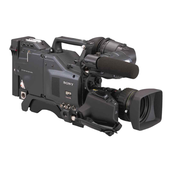
Product Configurations The eight models, DXC-D30F, DXC-D30K, DXC- and PAL versions and the components as shown in the D30L, DXC-D30H, DXC-D30PF, DXC-D30PK, figure below. The operation of the basic camera unit is DXC-D30PL, and DXC-D30PH, comprise both NTSC the same in all cases. DXC-D30F/D30PF DXC-D30K/D30PK DXC-D30L/D30PL... -
Page 9: Features
When the gain is set to either 18 dB or 24 dB, the gain with the EVV-9000/9000P Hi-8 VTR. Using an • S/N: 63 dB (DXC-D30) or 61 dB (DXC-D30P) Setup file system setting can be doubled (6 dB up) without increasing... -
Page 10: Location And Function Of Parts
Location and Function of Parts Features Freeze mix function (when using DSR-1/1P) Camera Head VTR data display The freeze mix function superimposes any previously recorded still picture on the viewfinder screen to When connected to a VTR, the DXC-D30/D30P is facilitate framing the subject when reshooting the Right side view able to display the following data on the viewfinder... - Page 11 Location and Function of Parts 1 EZ (“easy”) MODE button and indicator 5 A.IRIS (auto iris) MODE switch and indicator CAM/DL: This setting uses the DynaLatitude Note function, which finely adjusts the contrast of each Set this switch to the ON position when you want to be When you use the auto iris function (by setting the iris The recording time displayed when this switch is set to able to shoot immediately, with automatic adjustment...
- Page 12 Location and Function of Parts @º ZEBRA switch @¡ UP/ON button 6 SHUTTER switch 8 AUDIO LEVEL knob Set this switch to the ON position to display a zebra Use this button to open displays and to make “ON” Use this switch to set the shutter speed, CLS (clear When the DSR-1/1P is attached, you can use this knob pattern (diagonal stripes) in the viewfinder.
-
Page 13: Vcl-916Bya Zoom Lens
Use this connector to connect the switch for enabling Connect the lens connector. remote operation of the ClipLink function. !™ VF (viewfinder)connector (8-pin) For details of connectable switches, contact your Sony This is the connector for the DXF-40B/50B (or DXF- dealer. 40BCE/50BCE) viewfinder. -
Page 14: Dxf-701/701Ce Viewfinder
Location and Function of Parts 1 Focusing ring For close-up work, hold this button down while DXF-701/701CE Viewfinder Turn this ring to focus the lens on the subject. turning the MACRO ring. (See page 82.) 2 Manual zoom control 8 MACRO ring 1 BATT indicator For direct manual zoom control, set the ZOOM For close-up work, hold the MACRO button down... -
Page 15: Fitting A Vtr
http://getMANUAL.com Fitting a VTR Location and Function of Parts 5 GAIN UP indicator (orange) This section explains how to attach the DSR-1/1P to When replacing the camera head grip with a camcorder grip, see “Using the Camcorder Grip” (page 23). the camera head. -
Page 16: Using The Camcorder Grip
Fitting a VTR Using the Camcorder Grip Tighten the two screws in the grip connector and the two When using the camera head with a VTR as a screws in the should pad camcorder grip and the method for attaching it differ camcorder, you can replace the camera head’s grip section. - Page 17 Fitting a VTR Attaching a camcorder grip to the PVV-3/3P. Perform the first three steps in “Fitting a VTR”. Perform steps 2 and 3 in “Fitting a VTR”. Screw the connection plate (supplied with the grip for the DSR-130/130P) which If the viewfinder is attached, straddles the connection adjust the viewfinder to the...
-
Page 18: Fitting The Lens
Fitting the Lens In the case of the DXC-D30F/D30PF/D30K/D30PK Using the triangular mark as a model, the lens is already fitted. In other cases, use the guide, push the lens connector following procedure to fit the lens. into the LENS connector on the camera head, until it clicks into place. -
Page 19: Using Accessories
Remove any microphone from the viewfinder before attach the CAC-12 Microphone Holder. adaptor in the LC-421 Carrying Case. beginning. For details, consult your Sony dealer. Pull the viewfinder connector VF connector out of the VF connector on the Using an Optional Microphone font of the camera head. -
Page 20: Fitting To A Tripod
Using Accessories Fitting an optional microphone Fitting to a Tripod Use the following procedure to attach an optional First fit the VCT-U14 Tripod Adaptor to the tripod, ECM-670 Microphone. then mount the camera on the tripod adaptor. Loosen the screw of the CAC- Microphone adaptor 12 Microphone Holder, then open the holder and replace the... -
Page 21: Using The Carrying Case
• Select a camera cable to fit the camera input connector on the VTR you are using. • The maximum camera cable extent is 10 m (33 ft). For details, consult your Sony dealer. NP-1A/1B Battery Packs (maximum two) - Fasten straps. -
Page 22: Connecting A Number Of Cameras (Using A Camera Control Unit)
CCU-M5/M5P/M7/M7P Camera configuration. Control Unit to provide video and color sync between CCU-M5/M5P Camera Control cameras, and special effects and other devices to allow For details, consult your Sony dealer. Unit switching, wipes and so forth. VBS OUT TALLY/INTERCOM Note In the studio it may also be convenient to use a DXF- 75Ω... -
Page 23: Connecting A Number Of Cameras (Without Using A Camera Control Unit)
CA-537/537P DXC-D30/D30P DXC-D30/D30P CA-537/537P For details, consult your Anton Bauer products supplier or a) Requires the special-purpose DC-500 Battery Case. Sony dealer. Cannot be used with a camera adaptor. GEN LOCK IN Battery low indications Using Battery Packs VTR/CCU/CMA VIDEO OUT... -
Page 24: Camera Adaptor Power Supply
Power Supply Basic Procedure for Shooting Camera Adaptor Power Supply The camera adaptor automatically operates on power supplied to the VTR/CCU/CMA connector from the portable VTR, CCU-M7/M7P Camera Control Unit, CMA-8A/8ACE Camera Adaptor or other connected device. Note Before use, check that the device connected to the ZEBRA switch VTR/CCU/CMA connector is able to provide the Focusing ring... -
Page 25: Shooting With The Dsr-1/1P
http://getMANUAL.com Basic Procedure for Shooting Shooting with the DSR-1/1P If required, switch on the center marker and/or The DXC-D30/D30P docks with the DSR-1/1P to Press the VTR button on the camera head or the Reviewing the recording safety zone (basic menu page 6 and advanced configure the DSR-130/130P DVCAM Digital lens. -
Page 26: Using The Edit Search Function While Back Space Editing
Shooting with the DSR-1/1P Press the TAKE button when you find a shot Setting Mark IN/OUT points as you shoot Setting Cue points as you shoot Using the Edit Search Function where you would like to set a Mark OUT point. While Back Space Editing You can make edit search operations easier by Instead of continuing shots from scene to scene, you... -
Page 27: Using The Freeze Mix Function
Viewfinder Screen Indications Shooting with the DSR-1/1P Release the REV or FWD button when you find Press the UP/ON button when you see the image There are three types of indication screen which appear Status indications Display by holding the the tape location where you wish to continue you want to freeze. - Page 28 Viewfinder Normal Indications Viewfinder Screen Indications immediately, move the cursor to the menu During normal operation, the following items can be Displaying the advanced menu and number and then press the DOWN/OFF button. indicated in the viewfinder. switching to the normal indications •...
- Page 29 Viewfinder Normal Indications 5 Clip mode indication !¡ Audio recording level indicators Only when connecting the DSR-1/1P Note A “CLIP M” or “CLIP C” indication appears when These show the recording levels of audio channels 1 Meaning Indication Depending on the lens being used, this indication may you use the ClipLink function and record using the and 2 on the VTR.
-
Page 30: Viewfinder Basic Menu
B A T T : 1 3 . 0 V display area whenever the camera head’s automatic If an error message appears, contact your Sony dealer. To change the page or item self diagnostic function detects an abnormality. Be a) When both the DCC+ and DynaLatitude functions are set to OFF sure to access this page and perform error checking. - Page 31 EVS, CLS (60.4 Hz to 200.3 Hz) Setting the recording time in minutes MM:SS (see page 75) . DXC-D30P: 1/60 (normal value), 1/ 00:00 For details of this operation, see “Setup Files” (page 62). 250, 1/500, 1/1000, 1/2000, EVS, Press the MENU/STATUS switch to move the CLS (60.3 Hz to 201.4 Hz)
- Page 32 Viewfinder Basic Menu Press the UP/ON button to select the required Basic menu page 7 Basic menu pages 8 and 9 character. Each time you press the UP/ON button, the M A R K / C U E : M A R K The following display is shown when the DSR-1/1P is You can create a title of up to four lines, each of F R E E Z E : O F F...
-
Page 33: Viewfinder Advanced Menu
Viewfinder Basic Menu Viewfinder Advanced Menu Press the UP/ON button once. Bring up the advanced menu pages by setting the For details of this operation, see “Displaying the advanced menu and switching to the normal indications” (page 46). POWER switch to ON while pressing the UP/ON The title is superimposed to the picture displayed button up (see page 46). - Page 34 E X I T M E N U ( Y E Sm4) E X I T M E N U ( Y E S m4) E X I T M E N U ( Y E Sm4) a) For DXC-D30P: EBU75 a) For DXC-D30P: 70% Item...
- Page 35 http://getMANUAL.com Viewfinder Advanced Menu To set the camera ID EZ mode settings Advanced menu page 7 Advanced menu page 8 The following settings are set for the camera head Press the MENU/STATUS switch to move the when EZ mode has been selected. cursor to ID SET.
-
Page 36: Setup Files
Setup Files Press the UP/ON button to call up the file. To To call up files recorded onto a tape (when You can use setup files to reproduce a particular abort the call up operation, press the DOWN/OFF using the DSR-1/1P) configuration of settings. -
Page 37: Changing File Settings
Setup Files Page 10 Access advanced menu page 12. Changing File Settings PAGE12(NEXTm$ PREVm4) Item Settings PAGE12(NEXTm$ PREVm4) When using advanced menu page 10 or 11, you can –99 to ±0 (normal value) to FILE STORE FILE:*FILMLIKE change the settings about picture quality in setup files. Adjusts the saturation of the FILE STORE DESTINATION FILE... -
Page 38: Using Setupnavi And Setuplog With The Dsr-1/1P
Using SetupNavi and SetupLog with the DSR-1/1P Setup Files The SetupNavi function records the setup menu and Press the UP/ON button. Press the UP/ON button to store the file. To abort the save operation, press the DOWN/OFF button setup files onto a tape, so that the same settings can be (the screen returns to the screen shown in step 2). -
Page 39: Recording The Menu Settings Onto A Tape
Using SetupNavi and SetupLog with the DSR-1/1P The cursor (→) changes to the text entry cursor To abort the data recording while in progress Status display (page 2) Recording the Menu Settings (↓). Press the DOWN/OFF button. onto a Tape P L A T A P E N E A R E N D T C G... -
Page 40: White Balance Adjustment
White Balance Adjustment Adjusting the white balance ensures that as lighting Make the following settings on the camera. conditions change white objects remain white in the • POWER switch: ON SAVE image and tones remain natural. • OUTPUT/DL/DCC+ switch: one of the CAM The color of light emitted varies from one light source positions to another, and as the lighting changes the apparent... -
Page 41: Using The Preset White Balance Settings
White Balance Adjustment Warning messages for white balance adjustment Color temperatures of different light sources Using the Preset White Balance Message Meaning and corrections to be made Light source Color temperature (K) Settings AUTO WHITE Light level is too low. Natural Artificial -NG-... -
Page 42: Black Balance Adjustment
There are five shutter speeds, from s (DXC-D30) M5P is in the CAM position. change. s (DXC-D30P) to s. Increasing the shutter 2000 speed reduces blurring when shooting a fast-moving If black balance adjustment cannot be subject. -
Page 43: Setting The Clock And Timestamping Recordings
Flashing EXIT MENU (YESm4) indications head. Contact your Sony dealer for replacing the Press the MENU/STATUS switch as many times as lithium battery. Select whether to display a 12-hour clock (showing necessary until the normal indications appear. -
Page 44: Viewfinder Screen Adjustments
Using an optional part allows you to modify the adjustment range to –2 to +1 diopters or –0.5 to +3 diopters. For details, consult your Sony dealer........................................... 1) Diopter: A unit to indicate the degree of convergence or divergence of a bundle of rays. -
Page 45: Adjusting The Lens
http://getMANUAL.com Adjusting the Lens Flange Focal Length Adjustment Iris Adjustments It is necessary to adjust the flange focal length (the • When a lens is fitted for the first time distance from the lens flange to the plane of the image •... -
Page 46: Macrophotography
Adjusting the Lens Settings for Special Cases Macrophotography Settings for special cases Shooting conditions Setting Effect Use the macro function when the subject is less than The background is very bright, and the Set the A.IRIS MODE switch to BACK L, This lightens the foreground. - Page 47 In the event of operating problems If you should experience problems with the unit, contact your supplier or Sony service representative. Chapter 5 Adjustments and Settings Appendix...
- Page 48 When you are using a DSR-1/1P or PVV-3/3P, the (DXC-D30) 752 (horizontal) × 582 (vertical) Video S/N ratio 63 dB (typical) (DXC-D30) Warning indications 61 dB (typical) (DXC-D30P) (DXC-D30P) Camera Fault VTR action What to do 8.8 × 6.6 mm (corresponds to Registration 0.05% for all zones, without lens...
- Page 49 Infinity to 0.9 m WEX-2000 Wipe Pattern Extender DXF-50B/50BCE 5-inch Viewfinder (monochrome) Filter attachment threads There is a range of Sony products available to meet 77 mm dia., 0.75 mm pitch (on DXF-40B/40BCE 4-inch Viewfinder (monochrome) every conceivable video shooting requirement. For...
- Page 50 Chart of Optional Components and Accessories EC-0.5C2 Microphone Cable CCZ-A cable CCU-M7/M7P/M5/M5P Camera Control Unit ECM-690/672 and C-74 Microphone CCZ-A cable BVW-50/50P Betacam SP Camcorder CAC-12 Microphone Holder CCZQ-A cable VO-8800/8800P U-matic CCZJ-A cable VHS VTR CA-537/ 537P Camera CCZ-A cable VA-5/5P + BVV-5/5PS Adaptor DXF-50B/50BCE/40B/...
-
Page 51: Service Information
ES-12/12(P) board IF-532 board PR-216 board VA-169 board SW-790 board PA-188(G) board SW-791 board SW-792 board SW-793 board 2-2. REMOVAL OF CABINET 2-2-1. Removal of Side Plate Loosen the four screws respectively to remove the side plates. DXC-D30 (UC) DXC-D30P (CE) -
Page 52: Cautions On Removal Of Top Chassis
CN2, CN105, CN106, CN107 and CN123 on the MB-629 board. CN503 MB-629 board CN105 CN106 MB-629 board CN107 CN123 Disconnect the connector CN503. AT-110 board Remove the SW-790 board. Screws(B3 X 4) CN-1195 board CN503 SW-790 DXC-D30 (UC) DXC-D30P (CE) - Page 53 Remove the CCD unit from transport holder for replace- the two connectors, CN2 and CN14 on the MB-629 board. ment CCD unit supplied from the Sony Part Center. Pull out the Front unit Ass’y. When installing a new CCD unit, reverse the above procedures.
-
Page 54: Connectors And Cables
CCU : 5.0 ± 0.5 V 0.700 Vp-p 0.525 Vp-p NTSC: 0.286 Vp-p ± 10% CHROMA (G) OUT 0.300 Vp-p ± 10% PAL: 0.700 Vp-p 0.525 Vp-p Zo < 75 Ω ± 5% CHROMA (X) OUT DXC-D30 (UC) DXC-D30P (CE) - Page 55 Zi > 10 kΩ PB (VBS) (X) IN –20 dBm , Zo < 100 Ω MIC1 (X) OUT H: 4.0 to 5.5 Vp-p Zo < 2 kΩ CF/V RESET I/O L : 0 ± 0.4 Vdc MIC1 (Y) OUT DXC-D30 (UC) DXC-D30P (CE)
- Page 56 GND for VF VIDEO Zo > 1.1 kΩ BATT IND OUT VF VIDEO (X) OUT V = 1 Vp-p POWER +12 V DC OUT 10.6 V to 17.0 Vdc Zo < 1.1 kΩ GAIN UP IND OUT DXC-D30 (UC) DXC-D30P (CE)
- Page 57 Zo < 500 Ω, 5 Vp-p LD (VF) OUT MIC (3P, FEMALE) (EXTERNAL VIEW) Signal Specification MIC (G) IN GND for MIC –60 dB MIC (X) IN BALANCED MIC (Y) IN (0 dB = 0.775 V) DXC-D30 (UC) DXC-D30P (CE)
-
Page 58: Connection Connector
Slide the IC Socket cover in the opposite A-arrow direc- tion with holding the ROM. – With ROM mounted – AT-110 board IC socket cover – How to attach (Fig.1) – Push Clearance IC108 IC socket cover IC102 DXC-D30 (UC) DXC-D30P (CE) -
Page 59: Dc-Dc Converter Voltage
5WD EXT. DC OUT CN103-21pin -10 V CN117-1pin EXT. DC GND CN103-28pin +6.5 V CN114-20pin +3.1 V CN103-27pin +16 V CN103-25pin +5.3 V CN103-26pin +32 V CN103-23pin -5 V E1(GND) CN103-22pin +9 V MIC 2pin/1pin(GND) +48 V DXC-D30 (UC) DXC-D30P (CE) -
Page 60: Service Mode Operation
After performing the page of each menu, normally, the operation is performed the menu. When quitting the each menu, the screen is returned to the Menu Select Screen. . Connection: The menu screen is ensured by seen the viewfinder or MONITOR OUT of DXC-D30 (for NTSC) or DXC-D30P (for PAL). 2-10 DXC-D30 (UC) - Page 61 ± 0 ← B.KNEE S B.KNEE S ± 0 ← ± 0 ← R.KNEE P R.KNEE P ± 0 ← ± 0 ← B.KNEE P B.KNEE P FILTER FILTER ← ← COND IND COND IND 2-11 DXC-D30 (UC) DXC-D30P (CE)
- Page 62 MPKNEE4 Master Pre Knee point at -3dB gain and FM mode RPKNEE (D range 212%) :255 BPKNEE RPKNEE Rch Pre Knee Point fine Adjustment : 128 EXIT MENU (YES BPKNEE Rch Pre Knee Point fine Adjustment : 128 2-12 DXC-D30 (UC) DXC-D30P (CE)
- Page 63 EX board :TP-82 . Page 8 SC adjustment Measurement Point SC FREQ SC frequency adjustment ES board :TP-501 PAGE 8 (NEXT PREV SC-H SC-H adjustment VBS OUT SC FRE 2278 SC–H 1104 EXIT MENU (YES 2-13 DXC-D30 (UC) DXC-D30P (CE)
- Page 64 PREV changed. According to this, when replacing the TG-175 board or EEPROM (IC1) on the TG-175 board, the reset is needed. Contact R RG G RG your authorized Sony dealer. B RG R SUB G SUB B SUB EXIT MENU (YES...
- Page 65 :2070 (PAL) . Page 16 KNEE setting 3 (not in used) PAGE16(NEXT PREV R.KNEE S ± 0 ± 0 B.KNEE S : R.KNEE P : ± 0 ± 0 B.KNEE P : EXIT MENU (YES 2-15 DXC-D30 (UC) DXC-D30P (CE)
- Page 66 When the plural abnormality is occurred, the hexadecimal numbers of three digits are displayed in the total value of each error codes. When both HD and VD signals inputted to the PP LSI are abnormal, the PP-PMPD is displayed in the 003H. 2-16 DXC-D30 (UC) DXC-D30P (CE)
- Page 67 002H: The input VD signal (IF IC520, pin64) to the RC LSI is DSP COM. 000H MEMORY 000H abnormal. EXIT MENU (YES 001H: The input CF signal (IF IC520, pin63) to the RC LSI is abnormal. 2-17 DXC-D30 (UC) DXC-D30P (CE)
- Page 68 No.2 of CR signal) 002H: The connection between PR IC411 pin98 and IF IC520 pin95 is abnormal.(The No.1 of CR signal) 001H: The connection between PR IC411 pin95 and IF IC520 pin96 is abnormal.(The No.0 of CR signal) 2-18 DXC-D30 (UC) DXC-D30P (CE)
- Page 69 The PP LSI is carried out into communication with the microcomputer by six pins of pin41(CS), pin40(SCK), pin39(SDA0), pin38(SDA1), pin37(SDA2) and pin36(SDA3).If the communication between LSI and the microcomputer is abnormal, the abnormality of other item may be detected at the same time. 2-19 DXC-D30 (UC) DXC-D30P (CE)
- Page 70 . Page 22 Present unit condition indication This is the communication of the production. PAGE22(NEXT PREV This is not related to service. COND IND POWER 12.1V 224h R GAIN 7e6h B GAIN 800h IRIS POS 000h 000h EXIT MENU (YES 2-20 DXC-D30 (UC) DXC-D30P (CE)
-
Page 71: Alignment
• Digital voltmeter • Oscilloscope (100 MHz or more) • Vectorscope • Waveform monitor • B/W monitor (Sony PVM-91/122 or equivalent) • Color monitor (Sony PVM-1320 or equivalent) • AC Adaptor (Sony CMA-8/8A/8CE/8ACE) • Camera Adaptor (Sony CA-537/537P) • Frequency counter •... -
Page 72: Switch Setting Before Adjustment
3-1-3. Switch Setting Before Adjustment 3-1-4. Notes on Adjustment [DXC-D30, DXC-D30P] Note: (1) Before adjustment, be sure to allow for 10-minute warm- Switch setting for camera side up time. GAIN switch : 0 dB (2) When using the SERVICE menu, refer to “2-7. SERVICE OUTPUT/DL/DCC + switch : CAM/DCC + MODE OPERATION”. -
Page 73: Adjustment Item
3-3-8. Y (YC) Level Adjustment 3-3-9. Chroma (YC) Level Adjustment 3-3-10. VF SYNC/BLKG Level Adjustment 3-3-11. CCD Output Level Adjustment 3-3-12. Pedestal Adjustment 3-3-13. Shading Adjustment 3-3-14. Flare Adjustment 3-3-15. MIC LEVEL/MIC Level IND Adjustment 3-3-16. Character Position Adjustment DXC-D30 (UC) DXC-D30P (CE) - Page 74 Burst Spot 75% Note: • Partial difference between scale and signal level is caused by photographic error. • If the specifications are not met, carry out from “3-3-2. INT SC Phase Adjustment” through “3-3-9. Chroma (YC) Level Adjustment”. DXC-D30 (UC) DXC-D30P (CE)
-
Page 75: Camera Adjustment
B = 0 ± 5 mV R-Y CLP TP60 [for NTSC] [for PAL] C = 0 ± 5 mV B-Y CLP TP62 Note: After this adjustment, set the mode of Tektronix Waveform monitor 1765 to “WFM” mode. DXC-D30 (UC) DXC-D30P (CE) -
Page 76: Y/Sync/R-Y/B-Y Level Adjustment
: B = 300 ± 5 mV (NTSC) (PAL) NTSC : 700 ± 20 mV R-Y LVL TP60 : 525 ± 20 mV NTSC : 700 ± 20 mV B-Y LVL TP62 : 525 ± 20 mV DXC-D30 (UC) DXC-D30P (CE) -
Page 77: Chroma (Vbs) Level Adjustment
3. Then, perform above procedure item 1 again. [for NTSC] [for PAL] FL502 DL503 CN501 100% FL502 DL501 DL504 FL503 RV503 RV505 RV501 DL502 B-Y LEV C (Y-C) Y (VBS) RV504 RV502 C (VBS) Y (Y-C) ES-12 BOARD -A SIDE- DXC-D30 (UC) DXC-D30P (CE) -
Page 78: Y (Yc) Level Adjustment
[for PAL] [for NTSC] [for NTSC] [for PAL] [for PAL] FL502 DL503 CN501 FL502 DL501 DL504 FL503 RV503 RV505 RV501 DL502 B-Y LEV C (Y-C) Y (VBS) RV504 RV502 C (VBS) Y (Y-C) ES-12 BOARD -A SIDE- DXC-D30 (UC) DXC-D30P (CE) -
Page 79: Vf Sync/Blkg Level Adjustment
Specification : A = 165 ± 5 mV [for NTSC] [for PAL] Test point: TP21/extension board (VA-169 board) 1RV1/PA-189 (R) board Specification : A = 165 ± 5 mV PA-187 (B) BOARD - A SIDE - - A SIDE - PA-189 (R) BOARD DXC-D30 (UC) DXC-D30P (CE) -
Page 80: Pedestal Adjustment
4. In the following mode, adjust the UP switch or DOWN switch so that the waveform of the oscilloscope becomes flat. GND: TP38/extension board Test point Spec. Mode (VA-169 board) R SHAD CL101 G SHAD CL201 B SHAD CL301 3-10 DXC-D30 (UC) DXC-D30P (CE) -
Page 81: Flare Adjustment
DOWN switch where the mark just Adjust “R FLARE” and “B FLARE” alternately by UP disappears. switch or DOWN switch so that the carrier leakage level is minimum. Monitor screen or Viewfinder screen. 3-11 DXC-D30 (UC) DXC-D30P (CE) - Page 82 VF SDTL:±0 TONE XXdB VF TALLYx 2 XXdB "a" XXXX XXXX EXIT MENU (YES Adjusting point: 1CV1/MB-629 board “a” = “b” Specification: (The space between “a” and “b” are nearly equal) MB-629 BOARD -B SIDE- 3-12 DXC-D30 (UC) DXC-D30P (CE)
- Page 83 The material contained in this manual consists of information that is the property of Sony Corporation and is intended solely for use by the purchasers of the equipment described in this manual. Sony Corporation expressly prohibits the duplication of any...
- Page 84 Printed in Japan DXC-D30 (UC) Sony Corporation 1998. 1 08 DXC-D30P (CE) 9-977-263-12 Broadcasting & Professional Systems Company © 1996 Published by Global Support Promotion Dept.
Need help?
Do you have a question about the DXC-D30P and is the answer not in the manual?
Questions and answers