Table of Contents
Advertisement
Quick Links
Advertisement
Table of Contents

Related Manuals for Ikegami MKC-750UHD


Summary of Contents for Ikegami MKC-750UHD
- Page 1 MKC-750UHD Digital Process Compact 3CMOS Color Camera Operation Manual...
- Page 2 The software that we have manufactured is copyrighted by IKEGAMI TSUSHINKI CO., LTD. You may not reproduce or alter it, in whole or in part, without permission.
- Page 3 Safety Precautions For safe and correct usage Thoroughly read the “Safety Precautions” and the operation manual before using the unit. Keep them CAUTION carefully after reading and use as ready reference. When using the unit: Do not place a receptacle containing water or a small metallic piece on the unit! Pictorial Symbols If water spills in the unit, a fire or electric shock...
- Page 4 THE MKC-750UHD is authorized AAMI ES60601-1/EN60 difficult disconnecting the power plug. 601-1 Class IP rating of THE MKC-750UHD is IPX0. THE MKC-750UHD is a device for continuous operation. Hints on proper usage When using the unit: When using the unit in a water-place such as bathroom, poolside, etc., prevent water from flowing...
- Page 5 The MKC-750UHD is not AP APG equipment. The BATTERY for BT1 in MKC-750UHD, that should be used same model as below when you need to exchange it. MODEL : CR2032...
- Page 6 Guidance and manufacturer's declaration - electromagnetic emissions The Model MKC-750UHD is intended for use in the electromagnetic environment specified below. The customer or the user of the Model MKC-750UHD should assure that it is used in such an environment. Emissions test...
- Page 7 Guidance and manufacturer's declaration - electromagnetic emissions The Model MKC-750UHD is intended for use in the electromagnetic environment specified below. The customer or the user of the Model MKC-750UHD should assure that it is used in such an environment. Immunity test...
-
Page 9: Table Of Contents
Table of Contents Overview ........................9 Names and Functions of Parts ..................9 Camera Head ......................9 CCU Front ......................11 CCU Back ......................13 Service......................... 15 Connection Example .................... 15 Installation ......................17 Powering Up ......................18 Setting a White Balance ..................19 Adjusting a Paint .................... - Page 10 5.2.1 Setting ......................43 Scene File ......................45 5.3.1 Saving a Scene File ..................45 5.3.2 Initializing a Scene File .................. 45 5.3.3 Setting a Scene File ..................45 Saving and loading a set data ................46 5.4.1 Connecting of USB memory ................46 5.4.2 Saving a set data ...................
-
Page 11: Overview
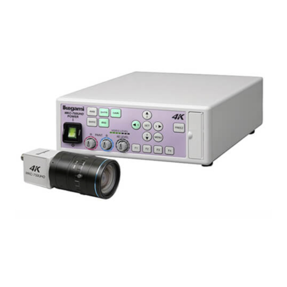
1. Overview MKC-750UHD is the 4K Camera equipped with high-definition video of 4K (3840 × 2160) and color reproduction as medical grade camera which is used for the surgical microscope or shadowless lamp system. It employs 3 CMOS system, performs 3840 x 2160 Full HDTV format with 1600TV lines horizontal resolution, S/N ratio with 56dB. - Page 12 The dedicated microscope adapter or the IRIS cable of a C-mount lens is connected here. LENS connector HR10A-7R-4S +12V IRIS HR10A-7R -4S PIN assignment Iris Cable side: HR10A-7P-4P (4-pin female plug) or Equivalent. Camera connector The camera connector of a dedicated camera cable is connected here. Please be aware that the camera connector is different in size between the camera head side and the CCU side.
-
Page 13: Ccu Front
(RED) volume (BLUE) Power button This is the power on/off Switch of the MKC-750UHD. Color bar button This outputs a color bar signal, included in the camera, to the video-out. It can be used for adjusting the brightness, contrast, etc. of a color monitor. (Page... - Page 14 brightness. Color correction volume (RED) This adjust finely the red color density on the output picture. Color correction volume (BLUE) This adjust finely the blue color density on the output picture. Brightness volume This adjust the brightness of a video. Arrow keys This is used for selecting the scene file and operating menu.
-
Page 15: Ccu Back
CCU Back RS-232C connector 4K OUT connector(SDIx4) FOOT SW connector Camera connector DVI-D OUT connector SYNC AC inlet connector HD-SDI(3G-SDI) OUT Equipotential connector (2 lines) terminal GEN LOCK connector 4K OUT connector(SDIx4) 4K signal (Quad Link Level-A)-input-compatible monitor etc. is connected here. RS-232C connector The personal computer etc. - Page 16 SYNC connector To synchronize the phase of a video with another system, this outputs a synchronizing signal to that system. A 3-value sync (HD) is supported. It assumes the synchronization applications in between the MKC cameras. For synchronization with other products I am afraid that I can not guarantee. Equipotential terminal This is used to make the potential of a cabinet equal to other equipment.
-
Page 17: Service
3. Service Connection Example 4K-Compatible monitor MKC-750UHD camera head Foot switch Camera cable coaxial cable 4 lines DVI-D cable coaxial cable DVI-compatible SDI-compatible How to connect to a 4K monitor, please check the operation manual that comes with the monitor. - Page 18 SW the IEC60529- IP1. DVI connector This connector outputs a digital signal. Connect a DVI cable to this connector. * Use a DVI cable with a ferrite core at both ends. Contact Ikegami if you are unable to obtain such a cable.
-
Page 19: Installation
Installation Notes on installation There is ventilation duct on the side of the CCU. CAUTION: Placed away 1.5cm or more from the wall so as not to block the ventilation ducts. Set up blocking the ventilation holes is cause of failure. Placed away 1.5cm or more from the wall so as not to block the ventilation ducts. -
Page 20: Powering Up
When power is turned off in the state of still an image frozen, that state will not be held even if power is turned on again, and MKC-750UHD is set to the normal shooting state. -
Page 21: Setting A White Balance
Setting a White Balance When using MKC-750UHD for the first time, or when the light source has been changed, adjust the White Balance. The white balance can be adjusted automatically. Operation Shoot a white photographic object on the screen largely, and press the white balance button. - Page 22 When the automatic adjustment is complete, the light of the auto white button will go out automatically.
-
Page 23: Adjusting A Paint
Adjusting a Paint After white balance adjustment it is possible with the MKC-750UHD to carry out fine adjustment of the red level and blue level/density of picture as desire of user. Operation Turn the color correction volume (red) and the one (blue) to make adjustments. -
Page 24: Adjusting An Ae Level
Adjusting an AE Level The MKC-750UHD can adjust a shutter speed, gain, and an Iris automatically, according to the preset exposure level. A screen becomes easy to see by raising the level when the screen is too dark, or reducing it when too bright. -
Page 25: Outputting A Still Image
Outputting a Still Image The MKC-750UHD can temporarily stop moving image output and switch to freeze frame output. Operation Press the freeze button. A still image will be output immediately. While a still image is output, the freeze button lights up. -
Page 26: Outputting Color Bars
Outputting Color Bars The MKC-700HD can output a color bar. This is used when adjusting the color monitor brightness, contrast, etc. Operation Press the color bar button. Color bars will be output immediately. While color bars are output, the color bar button is lit in green. Color bar button To restore a video from the camera, press the color bar button again. -
Page 27: Selecting A Scene File
Selecting a Scene File The MKC-750UHD can read them at any time by saving settings often used on beforehand in a scene file. A maximum of four scene files can be stored. Loading The arrow key corresponding to the currently selected scene file is lit. -
Page 28: Menu Operation
4. Menu Operation The MKC-750UHD has various kinds of functions that are very useful in service. A user can select and set these functions as desired. The basic procedure for operation is as follows. Operation Method When you press the menu button on the CCU front, a menu will open on a monitor screen, where you can set various kinds of camera functions. -
Page 29: Exposure
Exposure The exposure time, etc. can be adjust. Exposure Measurement Area MIDDLE AE Level Speed MIDDLE Peak Ratio Shutter AUTO Gain AUTO Line Mix Iris Control AUTO Item Description Measurement Area Adjusts the extent of a metering area. Carries out automatic adjustment of the shutter and gain, etc. - Page 30 This item concerns automatic adjustment of the Shutter shutter speed. When you make a shutter speed higher, brightness will change according to the speed. Under the lighting of a discharge lamp, such as a fluorescent lamp, much flicker may appear. AUTO According to the brightness of a video, a shutter speed will be adjusted to the optimum one automatically.
-
Page 31: Level
LEVEL The level of black, red, blue of video picture can be adjust. LEVEL Pedestal Flare Gamma Knee R Paint B Paint White Shading Item Setting Description Pedestal Adjusts the black level. Normally not used. -64~63 If the value is increased, the black sections become brighter. -
Page 32: Dtl
The detail enhancement can be set. Gain Boost 2MHz Item Setting Description Adjusts the detail enhancement level. Gain 0~31 Increasing the value, results in a sharper image. Sets the boost frequency for detail enhancement. Boost 2~16MHz The lower the value, the easier it is to carry out contour enhancement on the entire screen. -
Page 33: Color
Color The color reproducibility can be set. Color White Balance Chroma Matrix Color Correct Item Setting Description Sets white balance operation. White Balance AWB The white balance adjusted automatically. Press the SET button when this item is selected. ATW Automatically adjusts to the white balance relation pick... - Page 34 OFF Disable an adjustment. ON Enable an adjustment.
-
Page 35: Scene File
Scene File The settings information as a scene file can be read and save. Up to four scene files can be created. * For details of the setting, see Section 5.3 “Scene File”. Scene File Scene Number No.1 Store Scene READY Initialize SceneREADY... -
Page 36: Function Mode
Function Mode Other functions can be set. Function Mode Digital Zoom x1.0 Flip DNR Level Item Setting Description Magnification setting of electronic Digital zoom zoom. x1.0~x4.0 The center of the screen is zoomed up in units of 0.1 power. Sets the horizontal and vertical Flip... -
Page 37: Foot Switch
Foot Switch The movement of time to operate the foot switch can be set. Foot Switch Foot Switch 1 NONE Foot Switch 2 NONE Foot Switch 3 NONE Foot Switch 4 NONE Item Setting Description Foot Switch Carries out setting of operations when the foot switch is operated. -
Page 38: Function Key
Function Key The movement of time to operate the function key on the CCU front can be set. Function Key Key 1 NONE Key 2 NONE Key 3 NONE Key 4 NONE Item Setting Description Function Key Carries out setting of operations when the function key is operated. -
Page 39: Video Format
Video Format The video format can be set. Video Format Frame Rate 59.94Hz SDI Output 1080i DVI Output 1080p H Position V Position Genlock Center Marker Item Setting Description Select the frequency of the video output Frame Rate signal. Frequency is common to all of the output signal. - Page 40 H Phase Adjusts the horizontal phase for Genlock input. V Phase Adjusts the vertical phase for Genlock input. When the 3D system is configured, sets 3D Support whether to operate as a slave or as a master. Center Maker Displays the Center marker.
-
Page 41: Date/Time
Date/Time The date and time can be set. Date/Time Year 2016 Month Hours Minutes Seconds Setting READY 2016-03-02 11:34:20 Item Setting Description Year Month Hours Sets the date and time. Minutes Seconds Setting... -
Page 42: Others
Others The condition at the time of shipment from the factory can be return. Reading and writing data to a USB memory can be. Others Initialize READY USB Memory NO MEDIA Item Setting Description Initialize Press [READY] [START] [SET]. All the settings other than those for scene files will be initialized. -
Page 43: Information
Information The version information of the software appears. Information CCU Firmware V1.00-6162 CCU FPGA V1.00a-6155 Head FPGA V5.00e-6153... -
Page 44: Advance Use
SYNC input conditions: 3-value SYNC: 0.6 Vp-p / 75 5.1.1 Wiring Example Prepare two sets of the CCU and camera for MKC-750UHD. Connect the SYNC connector on the CCU (master) and the GENLOCK connector on the CCU (slave) with each other, using a coaxial cable. -
Page 45: Setting
5.1.2 Setting Observing the SYNC output waveforms of the master and the slave CCU, adjust PHASE so that H/V phases may become consistent with each other. The slave one (whose GENLOCK connector is connected) should be a target for the adjustment. - Page 46 Position You can set the position and size of a metering frame. When setting is nished, select QUIT and press the SET button to nish setting. Setting the Position Select Position and press the SET button to adjust the position of a metering frame. The frame size is not changed.
-
Page 47: Scene File
[Bottom&Right] Changing frame size Use the / / / keys to adjust the position. [Top&Left] Adjusts the size of left and upper sides of a metering frame. Enlarges with “ ”/“ ”key. Reduces with “ ”/“ ”key. [Bottom&Right] Adjusts the size of lower and right sides of a metering frame. Enlarges with “... -
Page 48: Saving And Loading A Set Data
Saving and loading a set data The set data is save to a USB memory. And, the set data save to a USB is loaded. 5.4.1 Connecting of USB memory Open the maintenance door, and insert USB memory into USB connector. Precautions on USB memory USB memory equipped with a protective function by password is not support. -
Page 49: Saving A Set Data
5.4.2 Saving a set data Points the cursor to the [READY] of [USB Memory], selects [CCU USB] by the [ ] [ ] buttons, presses the [SET]. The set data is saved to a USB memory. During save to the USB memory, ”USB Memory Busy” is appear at the bottom of the screen. -
Page 50: Loading A Set Data
”USB Memory Error” is appear when failing to save a set data. Others Initialize READY USB Memory READY USB Memory Error Precautions on failing to save. When failing to save a set data, delete a data of USB memory and increase a free space and use another memory. -
Page 51: Support Function
A set data saved in our other models can not be read to MKC-750UHD. 3D support function By using 3D support function of this machine, it is possible to change setting various kinds of camera functions simultaneousness of left and right and adjust easily when 3D system is constructed using this two machines. - Page 52 Setting the master and the slave Connect SYNC connector of the CCU made a master and GENLOCK connector of the CCU made a slave using a coaxial cable. And connect RS- 232C connector comrade using RS-232Ccross cable (D-Sub 9-pin Female). Connect the two CCU and the monitor.
-
Page 53: Linkage The Operation Panel And The Menu
If disappears after the lamp of maintenance USB port is lighted a few seconds, the setting is completed. Precautions During Connection Before connection, always power OFF the camera. 5.5.2 Linkage the operation panel and the menu When the setting is finished, [White balance], [Auto shutter], [Auto sensitivity], [Auto Iris] and [Set value of each volume] etc. -
Page 54: Default Settings
6. Default Settings Exposure The 2nd hierarchy The 3rd hierarchy Item Default Setting Item Default Setting Measurement Area MIDDLE [NARROW] [MIDDLE] [FULL] [CIRCLE] [USER] AE Level -128 Speed Middle [SLOW] [MIDDLE] [FAST] Peak Ratio Shutter AUTO [MANUAL] Shutter Speed [1/4] [1/10000] [Auto] Shutter Limit... -
Page 55: Dtl
The 2nd hierarchy Item Defaults setting Gain 0 31 Boost 2MHz 2 16MHz Color The 2nd hierarchy The 3rd hierarchy Item Defaults setting Item Defaults setting White Balance [AWB][ATW] [MANUAL] R Gain -128 127 B Gain -128 127 Chroma -128 127 Matrix [OFF] [ON]... -
Page 56: Scene File
Scene File The 2nd hierarchy Item Defaults setting Scene Number No.1 [No.1][No.2][No.3][No.4] Store Scene READY [READY] [No.1][No.2][No.3][No.4] Initialize Scene READY [READY] [No.1][No.2][No.3][No.4] Function Mode The 2nd hierarchy Item Defaults setting Digital zoom x1.0 x1.0 x4.0 Flip [OFF][H FLIP][V FLIP][ROTATE] DNR Level 0 31 Foot Switch The 2nd hierarchy... -
Page 57: Video Format
Video Format The 2nd hierarchy The 3rd hierarchy Item Defaults setting Item Defaults setting Frame Rate 59.94Hz [59.94Hz][50Hz] SDI Output 1080i [1080p][1080i] DVI Output 1080p [1080p][1080i] H Position -32 32 V Position -8 8 Genlock [OFF] [AUTO] H Phase -128 127 V Phase -128 127 3D Support... -
Page 58: Specification
7. Specification Rating (1) Lens mount C-mount (2) Optical system RGB prism (3) Image pickup device 1/3-inch CMOS sensor x 3 (rolling shutter) (4) Outputs pixels 4K output 3840×2160 pixels 2K output 1920×1080 pixels (5) Scan mode Progressive scan (6) External synchronization input 3-value SYNC: 0.6 Vp-p / 75 (7) Video output signal 4K output... -
Page 59: Function
(2) S/N ratio 56 dB targeted ( and detail OFF) (3) Sensitivity Standard 2000lx F8 / 3200K or more Function (1) Gain Control function AUTO/MANUAL (2) White Balance function AWB/MANUAL/ATW (3) Shutter Control function AUTO/MANUAL (4) White Shading correction function (5) Flare correction function (6) Photometry area variation function (7) Picture freeze function... -
Page 60: Appearances
8. Appearances Camera Head... - Page 62 MEMO...
- Page 63 © Ikegami Tsushinki Co., Ltd. July 2016 All rights reserved. Reproduction or duplication, without permission of Ikegami Tsushinki Co., Ltd. of editorial or pictorial content in whole or in part, in any manner, is prohibited. Specifications and design are subject to change without prior notice.
- Page 64 Ikegami Tsushinki Co., Ltd. 5-6-16, Ikegami, Ohta-ku, Tokyo, 146-8567, Japan Phone : +81-(0)3-5700-4114 Fax : +81-(0)3-5748-2200 E-Mail : info_e@ikegami.co.jp URL : http://www.ikegami.co.jp/en/ Ikegami Electronics (U.S.A.),Inc. 37 Brook Avenue, Maywood, New Jersey 07607, U.S.A. Phone : +1-201-368-9171 Fax : +1-201-569-1626 E-Mail : engineering@ikegami.com, service@ikegami.com URL : http://www.ikegami.com...
Need help?
Do you have a question about the MKC-750UHD and is the answer not in the manual?
Questions and answers