Table of Contents
Advertisement
Available languages
Available languages
Quick Links
Advertisement
Chapters
Table of Contents

Related Manuals for Ikegami ICD-809


Summary of Contents for Ikegami ICD-809
-
Page 1: Instruction Manual
INSTRUCTION MANUAL (NTSC version) Color Camera MODEL ICD-809 OUTDOOR USE WARNING WARNING – TO PREVENT FIRE OR ELECTRIC SHOCK, DO NOT EXPOSE THIS APPLIANCE TO RAIN OR MOISTURE. Ikegami Tsushinki Co., Ltd. -
Page 2: Table Of Contents
Thank you very much for choosing this Ikegami high quality TV Camera. Please read this Instruction Manual carefully to keep your Ikegami camera at peak performance for longer service duration. All Ikegami cameras are designed and manufactured with utmost care and craftsmanship to provide long life and high quality performance, if it is properly used and maintained as outlined in this manual. - Page 3 The exclamation point within an equilateral triangle is intended to alert the user to the presence of important operating and maintenance (servicing) instructions in the literature accompanying the appliance. NOTE: This equipment has been tested and found to comply with the limits for a Class B digital device, pursuant to Part 15 of the FCC Rules.
-
Page 4: Handling Precautions
The camera is best suited for general surveillance purposes, from single camera operation to large scale integrated systems for visual information management. * I-LAN : Ikegami security surveillance system control software for RS-485. Refer to the Section 5-4-10 for Remote control and RS-485... -
Page 5: Features
Camera setup can be easily done locally with control switches on the camera rear panel using OSD, On Screen Display, or remotely by I-LAN, Ikegami's camera control software over RS-485 link. In addition, an optional remote setup and control unit, such as the RCU-801 can be used for this purpose via coaxial video cable connection. - Page 6 Thanks to the automatic tracking white balance control (ATW), the white balance adjusts itself no matter how great the subject's color temperature fluctuates. The ICD-809 provides various useful white balancing functions to meet the most testing of users requirements resulting in full time automatic color balance, extended spectrum range balancing (ATW-1 and ATW-2), normal one-touch white balance and manual balancing by individual R and B gain controls.
- Page 7 (11) Lens flange back focus adjustment: An easy adjustment can be done by a rotating disk mechanism and convenient side access port-side Lock screw. This may be useful when changing lens from single focal lens, vari-focal lens, long focal lens, or zoom lenses, or vise versa.
-
Page 8: Names Of Parts And Their Functions
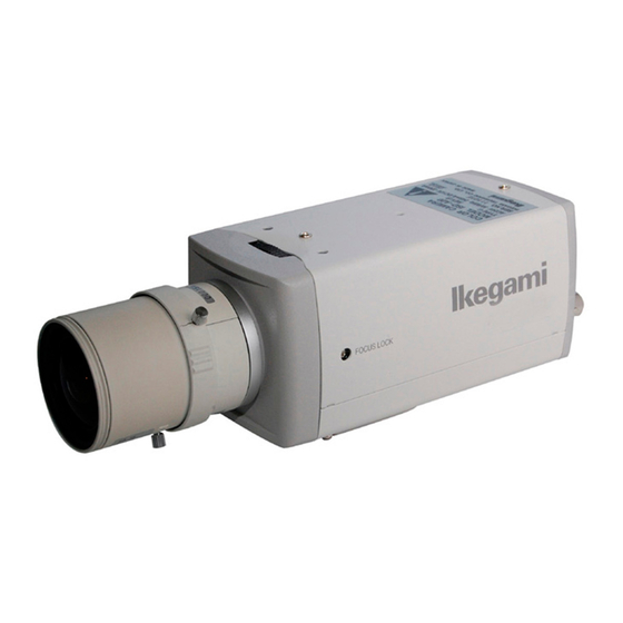
4. Names of parts and their functions (LEFT VIEW) (TOP VIEW) (RIGHT VIEW) A VIEW (REAR VIEW) GENLOCK IN GENLOCK IN CLASS2 AC24V60Hz4.3W DC12V4.2W (AC100V) (AC24V/DC12V) - Page 9 Lens mount (CS mount) This is used to mount the lens on the camera. Many types of CS mount lens can be used. Lens flange back focus adjuster To be used to adjust the lens flange back focal distance (distance between lens mounting edge and image focal point), if the camera fails to come into focus with the lens' focus ring, this can be used for re-adjustment of lens back focus when replacing lens.
- Page 10 • For the DC controlled type auto iris lens Set the lens selector switch to DC position. – Connector cable wires – Auto iris lens 1. Damping coil (-) 2. Damping coil (+) 3. Driving coil (+) 4. Driving coil (-) * Connect the wires as shown above.
- Page 11 Terminal switch for RS-485 In RS-485 communication link , turn this switch to ON side for one-to-one control, or turn it to OFF side for daisy-chain(loop connection). (For use in daisy-chain connection, turn ON the terminal switch of the last device in the link.) RS-485 connection terminal block To be used for RS-485 connection.
-
Page 12: Operation
5. Operation 5-1. User setup The ICD-809 series camera has a provision of a camera setup and memory function for camera ID setting, sync system selection, various picture quality setups for optimum reproduction, back light compensation spot area setting, Privacy Mask settings, Day/Night change-over thresh-hold settings. -
Page 13: Entering The Setup Mode And Its Basics
5-3. Entering the setup mode and its basics 5-3-1. SETUP MENU (Main menu) Hold down the E button longer than 2 seconds, and the menu at left appears onscreen. A highlighted item is now selected. (1) CAMERA ID Up to 24 alpha-numeric characters can be displayed on screen. -
Page 14: Setup Procedures
5-3-2. SPECIAL MENU Highlight EXIT on the SETUP MENU screen. Hold down the L and R buttons together, and the screen at left appears on screen. (1) CHROMA To be used to adjust the Chroma level. (2) DETAIL To be used to adjust the details. (3) PEDESTAL Pedestal level control (4) MATRIX... - Page 15 (2) ID characters setting Keep CAMERA ID highlighted and press the E button. The screen appears as shown on the right figure. ID Setting for Line and Starting point: For positioning the cursor, choose arrow marks, ,and push R or L button. Choose desired characters, or numbers, Use buttons of U, D, L, or R to do it.
- Page 16 5-4-2. DAY/NIGHT (1) With the L and R buttons, make the AUTO, COLOR or B/W (Monochrome) setting. AUTO Automatic switching is made: high- quality color images during the day, and high-sensitivity monochrome pictures at night. Press the E button, and the screen at right shows up. •...
- Page 17 5-4-3. SHUTTER (1) This mode is effective, when the light control is LENS mode. (2) By L or R button, high speed shutter can be valid for OFF, FL, 1/125, 1/250, 1/500, 1/1000, 1/2000, 1/4000, 1/10,000, or Variable. (3) VARIABLE Speed of shutter can be changed variably by L or R button.
- Page 18 (4) WIDE BLC If the picture turned to white and make it difficult to observe, try this to have better picture. This WIDE BLC makes compensation range larger to have moderate brightness level make a picture comfortable to eyes. (5) IRIS LEVEL This is displayed when using DC Iris lens.
- Page 19 5-4-5. GAIN (1) By L or R button, the gain control modes can be selected. This fixed-gain mode keeps the sensitivity low for brighter spots. This can be used for relatively comfortable picture reproduction with less video noise. Normally it is used with ample light condition. This fixed-gain mode keeps the sensitivity middle between HIGH and LOW.
-
Page 20: White Balance
5-4-6. WHITE BALANCE (1) By L or R button, The white balance mode can be selected. ATW-1 : (Factory Set Position) Automatically, white balance is controlled. ATW-2 : In this mode, the white balance control is made. But this ATW-2 mode covers wider range in the light spectral to cover the Sodium lighting. - Page 21 5-4-7 SYNC (1) By L or R button, INT, LL, EXT VS or EXT VBS can be selected. (2) INT = Internal Lock This is for internal sync lock mode, controlled by internal crystal oscillator. (3) LL = Line Lock This is for AC line lock mode.
- Page 22 5-4-8. MENU LOCK To prevent un-intentional or intentional setup parameter change, this Menu Lock function is provided for protection. The menu lock function protects saved setting parameters against accidental or intentional alteration. (1) To Lock To secure the saved setting parameters to make it ON, using E button. (2) Operation When locked, Only EXIT is effective and all the other actions are invalid.
- Page 23 (7) P.MASK With E button, Privacy masking (P.Mask, hereafter) control mode is available. P.MASK can be set maximum 8 (eight) points. Set to make it active (valid) or not. By using U or D button, choose desired Mask number/s, and make it valid or invalid by L button for ON (valid) or R button for OFF (invalid).
- Page 24 (8) RS-485 ID Camera ID number can be set in 1 to 207 with R or L button. (9) LANGUAGE Language for the Menu screen can be selected, either English or French. (10) RET To return to the Main Menu. (11) EXIT To save the setup parameters, and to quit.
- Page 25 5-4-10. Communication with control device (RS-485) The camera can be controlled from a control terminal (PC, for example), or the remote control unit provided by Ikegami, over RS-485 Link. The RS-485 is the recommended standard by EIA for a serial data communication, one class higher than RS-422 which is for Multi-drop connection, but the 485 is the Multi-points connection type.
-
Page 26: Warranty And After-Sale Service
Warranty accompanies this product. Read and fill out the warranty card that you have received at your dealer. Keep this card in a safe place. ● Please consult Ikegami Electronics (U.S.A.) Inc. or Ikegami Electronics (Europe) GmbH or your dealer for full warranty information. Your dealer will repair or replace free of charge within the warranty period according to the warranty coverage. -
Page 27: Specifications
7. Specifications (1) Image Sensor: 1/3-inch High Sensitive OCML IT CCD (2) Pixel Number: Approx. 380,000 pixels, 768(H) x 494 (V) (NTSC) (3) Scanning system: 525 TV lines, 60 Hz, 2 : 1 interlace in NTSC (4) Sync system: INT/LINE-LOCK (phase adjustable) (Line- lock not usable where the power frequency and the camera's vertical frequency are different from each other or when the... - Page 28 (15) Auto iris function: Compatible with VIDEO iris and DC iris (switchable, with DC iris level adjuster) (16) Camera ID: 1 Line Up to 24 characters (alphanumeric and symbols) (17) Local setup: Selectable and adjustable with on-screen display using pushbuttons on the camera rear panel;...
- Page 29 (27) Input/output connectors: • VIDEO OUT; BNC • GENLOCK IN; BNC • LENS; 4P (E4-191J-150 type) • DC 12V/AC 24V input; 2-pin terminal block • RS-485 input/output; 5-pin terminal block (28)Accessories: Instruction Manual, 1 copy * Specifications and design are subject to change for product improvements without notice.
- Page 30 Muchas gracias por haber elegido esta cámara de TV de alta calidad de Ikegami. Lea cuidadosamente este manual de instrucciones para mantener su cámara en las mejores condiciones de funcionamiento durante el mayor tiempo posible. Todas las cámaras de Ikegami han sido diseñadas y fabricadas con el máximo cuidado y destreza para proporcionar una larga duración y un rendimiento de alta calidad,...
- Page 31 El signo de exclamación dentro de un triángulo equilátero tiene la finalidad de avisar al usuario de la presencia de instrucciones de funcionamiento y mantenimiento (reparaciones) importantes en los manuales que acompañan al aparato. NOTA: Este equipo ha sido probado y ha demostrado cumplir con los límites establecidos para los dispositivos digitales de Clase B, de conformidad con el Apartado 15 de las Normas de la FCC.
-
Page 32: Precauciones De Manejo
1. Precauciones de manejo • No instale la cámara en un lugar donde se salpique agua o donde haya mucha humedad. • No utilice la cámara donde la temperatura ambiental sea inferior a -10°C o superior a +50°C. Las imágenes y las piezas componentes podrían ser afectadas o la cámara podría funcionar mal. -
Page 33: Generalidades
* I-LAN: Software de control de sistemas de vigilancia de seguridad de Ikegami para RS-485. Consulte la sección 5-4-10 para conocer más acerca del control remoto y RS-485 3. - Page 34 (3) Función de configuración de cámara remota o local y memoria de parámetros La cámara de la serie ICD-809 está equipada con una función de memoria y configuración de cámara controlada por microchip. La configuración de la cámara se puede hacer de forma fácil localmente, empleando los...
- Page 35 balance automático de los colores a tiempo completo, un balance de gama de espectros ampliada (ATW-1 y ATW-2), un balance del blanco normal con un solo toque y un balance manual para los controles de ganancia R y B individuales. (7) Imagen de alta calidad y alta resolución La cámara ha sido diseñada para que haga poco ruido y que la imagen no tenga borrosidad.
-
Page 36: Nombres De Las Partes Y Sus Funciones
4. Nombres de las partes y sus funciones (VISTA DEL LADO IZQUIERDO) (VISTA SUPERIOR) (VISTA DEL LADO DERECHO) A VIEW VISTA A (VISTA DEL LADO TRASERO) GENLOCK IN GENLOCK IN CLASS2 AC24V60Hz4.3W DC12V4.2W (CA 100 V) (CA 24 V/CC 12 V) - Page 37 Montura del objetivo (Montura CS) Ésta se utiliza para montar el objetivo en la cámara. Se pueden utilizar muchos tipos de monturas CS. Ajustador de distancia focal de brida del objetivo Se utiliza para ajustar la distancia focal de brida del objetivo (distancia entre la cara de montaje del objetivo y el plano focal).
- Page 38 • Para el objetivo de iris automático del tipo controlado por DC Ponga el conmutador selector del objetivo en la posición DC. Objetivo de iris – Conductores del cable del conector – automático 1. Bobina de amortiguamiento (-) 2. Bobina de amortiguamiento (+) 3.
- Page 39 Conmutador de terminal para GEN-LOCK Este conmutador sirve para terminar la señal GEN-LOCK con una impedancia de 75 ohmios cuando la conexión de bucle se hace para la alimentación de señales del sincronizador de señales de vídeo. Para terminar, ponga este conmutador en ON.
-
Page 40: Funcionamiento
5. Funcionamiento 5-1. Configuración del usuario La cámara de la serie ICD-809 dispone de función de configuración y memoria para poner la identificación de la cámara, selección del sistema de sincronización, varias configuraciones para que la calidad de la imagen de reproducción sea óptima, configuración del área del punto de compensación de luz de fondo, configuración... -
Page 41: Entrada En El Modo De Configuración Y Sus Puntos Básicos
5-3. Entrada en el modo de configuración y sus puntos básicos 5-3-1. SETUP MENU (Menú principal) Mantenga pulsado el botón E durante más de 2 segundos y el menú de la izquierda aparecerá en la pantalla. Ahora se selecciona un elemento resaltado. -
Page 42: Procedimientos De Configuración
5-3-2. SPECIAL MENU (Menú especial) Haga resaltar EXIT en la pantalla SETUP MENU. Mantenga pulsados juntos los botones L y R y aparecerá la pantalla de la izquierda. (1) CHROMA Se utiliza para ajustar el nivel de croma. (2) DETAIL Se utiliza para ajustar los detalles. - Page 43 (2) Selección de caracteres de identificación Mantenga resaltado CAMERA ID y pulse el botón E. La pantalla aparece como se muestra en la figura de la derecha. Selección de identificación para línea y punto de inicio Para posicionar el cursor, elija las marcas de flechas , y luego pulse el botón R o L.
- Page 44 5-4-2. DAY/NIGHT (Día/noche) (1) Seleccione AUTO, COLOR o B/W (blanco y negro) con los botones L y R. AUTO Se hace el cambio automático: imágenes en color de alta calidad durante el día e imágenes en blanco y negro de alta sensibilidad durante la noche.
- Page 45 5-4-3. SHUTTER (Obturador) (1) Este modo resulta eficaz cuando el control de luz está en el modo LENS. (2) Con el botón L o R se puede elegir entre las opciones OFF, FL, 1/125, 1/250, 1/500, 1/1000, 1/2000, 1/4000, 1/10,000 o Variable para el obturador de alta velocidad.
- Page 46 (4) WIDE BLC Si la imagen se pone blanca y resulta difícil verla, pruebe con este modo para mejorarla. Este WIDE BLC amplia el margen de compensación para obtener un nivel de brillo moderado y hacer que la imagen resulte confortable para los ojos.
- Page 47 5-4-5. GAIN (Ganancia) (1) Los modos de control de ganancia se pueden seleccionar con el botón L o R. Este modo de ganancia fija mantiene baja la sensibilidad para obtener puntos más brillantes. Este modo se puede utilizar para reproducir imágenes relativamente confortables con menos ruido de vídeo.
- Page 48 5-4-6. WHITE BALANCE (Balance del blanco) (1) El balance del blanco se puede seleccionar con el botón L o R. ATW-1 (Posición de ajuste de fábrica) El balance del blanco se controla automáticamente. ATW-2 : El control del balance del blanco se hace en este modo. Además, ATW-2 cubre una gama más amplia del espectro de luz que incluye hasta la luz producida por lámparas de sodio.
- Page 49 5-4-7. SYNC (Sincronización) (1) INT, LL, EXT VS o EXT VBS se pueden seleccionar con el botón L o R. (2) INT = Bloqueo interno Esto es para el modo de bloqueo de sincronización interna, controlado por oscilador de cristal interno. (3) LL = Bloqueo de línea Esto es para el modo de bloqueo de línea de CA.
- Page 50 SC FINE Después del ajuste de SC COARSE indicado anteriormente, el ajuste preciso de la fase de subportadora se puede controlar con el botón L o R. 5-4-8. MENU LOCK (Bloqueo de menús) La función de bloqueo de menús se ha incluido para impedir cambiar sin querer, o queriendo, los parámetros de configuración.
- Page 51 (5) MATRIX Seleccione el modo de matriz A o B. En condiciones normales se recomienda el modo A, pero en casos especiales como, por ejemplo, bajo la luz de lámparas fluorescentes o en interiores, el modo B resulta posiblemente mejor para obtener unas imágenes óptimas.
- Page 52 2) Reposición de la zona de enmascaramiento Mueva el cursor a MOV y pulse el botón E. Con el botón U, D, R o L se podrá reposicionar toda la zona de enmascaramiento. Pulse el botón E para establecer una posición y volver a la pantalla de ajuste de la zona P.MASK.
- Page 53 5-4-10. Comunicación con dispositivo de control (RS-485) La cámara puede ser controlada desde un terminal de control (un PC, por ejemplo) o con la unidad de control remoto suministrada por Ikegami, a través del enlace RS-485. RS-485 es la norma recomendada por la EIA para la comunicación de datos en serie, una clase superior a RS-422 que es para la conexión entre más de dos...
-
Page 54: Garantía Y Servicio Postventa
● Consulte a Ikegami Electronics (U.S.A.) Inc., a Ikegami Electronics (Europe) GmbH o a su concesionario para obtener una información completa de la garantía. Su concesionario reparará o reemplazará el producto libre de todo gasto siempre que no haya vencido el periodo de la garantía y se cumplan con... -
Page 55: Especificaciones
7. Especificaciones (1) Sensor de imagen: CD IT OCML de alta sensibilidad y 1/3 de pulgada (2) Número de píxeles: 380.000 píxeles aproximadamente, 768 (H) x 494 (V) (NTSC) (3) Sistema de exploración: 525 líneas de TV, 60 Hz, entrelazado 2 : 1 en NTSC (4) Sistema de sincronización: INT/LINE-LOCK (fase ajustable) (El bloqueo... - Page 56 (15) Función de iris automático: Compatible con el iris VIDEO y el iris DC (cambiable, con ajustador de nivel del iris DC) (16) Identificación de la cámara: 1 línea Hasta 24 caracteres (alfanuméricos y símbolos) (17) Ajuste local: Seleccionable y ajustable con la visualización en pantalla utilizando pulsadores del panel trasero de la cámara;...
- Page 57 (27) Conectores de entrada/salida: • VIDEO OUT; BNC • GENLOCK IN; BNC • LENS; 4P (tipo E4-191J-150) • Entrada de 12 V CC/24 V CA; bloque de terminales de 2 contactos • Entrada/salida RS-485; bloque de terminales de 5 contactos (28) Accesorios: Manual de instrucciones, 1 copia * Las especificaciones y el diseño están sujetos a cambios sin previo aviso.
-
Page 58: External Appearance
8. External Appearance (AC24V/DC12V type) 1"-32UN-2B 2-1/4"-20UNC COLOR CAMERA I C D - 8 0 9 MODEL TYPE REV. AC24V 60Hz 4.3W/DC12V 4.2W SER.NO. I K E G A M I T S U S H I N K I C O . , LT D. M A D E I N J A PA N GENLOCK IN CLASS2... - Page 59 (AC100V type) 1"-32UN-2B 2-1/4"-20UNC GENLOCK IN...
- Page 60 9. Setup Menu...
- Page 62 Memo...
- Page 64 ■ Ikegami Electronics (U.S.A.), Inc. 37 Brook Avenue, Maywood, N.J. 07607, U.S.A. Phone: (201) 368-9171, FAX (201) 569-1626 www.Ikegami.com ■ Ikegami USA, Los Angels Office: 2631 Manhattan Beach Blvd., Redondo Beach, C.A. 90278 Phone: (310) 297-1900, FAX (310) 536-9550 www.Ikegami.com ■...
Need help?
Do you have a question about the ICD-809 and is the answer not in the manual?
Questions and answers