Table of Contents
Advertisement
Quick Links
Advertisement
Table of Contents

Related Manuals for Ikegami MKC-307


Summary of Contents for Ikegami MKC-307
- Page 1 MKC-307 Digital Process Compact 3CCD Color Camera Operation Manual...
- Page 2 About MKC-307 Operation Manual The copyrights of this document belong to Ikegami Tsushinki Co., Ltd. The whole or part of this product and manual may not be reproduced, copied, reprinted, or modified without our prior permission. The specifications of this product and the contents described in this manual are subject to change without notice.
- Page 3 Continuing to use the product may cause fire or electric shock. Please contact dealer sales representative. Do not use damaged (exposed conductor, broken wire, etc.) power supply cable! Continuing to use the product may cause fire or electric shock. Please contact dealer sales representative. MKC-307 0710 VOL1(U)(E)
- Page 4 Neglecting this caution may cause fire. Installation Do not block the vent holes for this product! The MKC-307 is authorized UL60601 Class I . Blocking the vent holes may cause heat to accumulate internally and may cause fire. Please do...
-
Page 5: Table Of Contents
Image Enhancement ......................28 Overlay ..........................28 Trigger ..........................29 Miscellaneous........................29 4. Specifications .......................... 30 Rating ..........................30 Performance........................31 Functions..........................31 Optional functions ....................... 31 5. Appearance ..........................32 Camera Head ........................32 CCU............................. 32 MKC-307 0710 VOL1(U)(E) -
Page 6: Part Names And Functions
Connects to the focus cable for optional microscope adapter CXA-301R. The connector functions are described on the next page. IRIS Connector Connects to the IRIS cable for a special microscope adapter or 1/2-inch C mount lens. The connector functions are described on the next page. MKC-307 0710 VOL1(U)(E) - Page 7 It may also cause damage to the optical filter during attachment. Please notify our sales representative if you wish to remove the infrared cut filter. FOCUS Connector IRIS Connector (HR10A-7R-4P) (HR10A-7R-4S) FOCUS +12V IRIS MKC-307 0710 VOL1(U)(E)
-
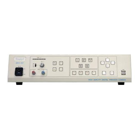
Page 8: Ccu Front
Outline Enhancement Button Power Switch This is the switch to turn ON/OFF the power supply to the MKC-307. When it is ON, the Ikegami logo lights up in blue. The product is turned ON by pressing the top of the switch and OFF by pressing the bottom of it. - Page 9 1/60 sec. However, this setting is not suited to rapidly moving objects or objects whose movements need to be captured in real time because image updating depends on the shutter speed. The maximum shutter speed value can be changed using this setting. MKC-307 0710 VOL1(U)(E)
- Page 10 Maintains the output level on image signals to a certain level by controlling the shutter speed automatically. Automatic switching is possible from 1/60 second to 1/10000 second. By combining this button with the Gain Button , an optimal image can be output regardless of the brightness of the subject. MKC-307 0710 VOL1(U)(E)
- Page 11 Still image mix: The same function as Still Image Mix Button Still image saving for mix: Saves the still image for still image mix. It may not be used depending on the menu settings. MKC-307 0710 VOL1(U)(E)
- Page 12 . For configuration of menu items, please refer to the section on menu operation. Select Button This button is pressed to confirm the item to be configured when the menu is displayed. Please refer to the section on menu operation. MKC-307 0710 VOL1(U)(E)
-
Page 13: Ccu Rear
DV terminal. * Please be sure to read “Notes on DV connection” on the next page when using DV OUT. S-VIDEO OUT Connector Outputs Y/C VIDEO signals. Connects to monitors, etc. with S-VIDEO input through an S-VIDEO cable (optional). MKC-307 0710 VOL1(U)(E) - Page 14 Connects to the cable from the remote controller for the optional microscope adapter CXA-301R. FOCUS Connector (HR10A-7R-5S) FOCUS FOOT SW Connector It can connect a FOOT SW cable from the double foot switch (optional). Front panel function button F1 is assigned as FOOT SW-1 and F2 as FOOT SW-2. MKC-307 0710 VOL1(U)(E)
- Page 15 In addition, Y/C output and VBS output are also available. RGB Connector (High-density D-sub15-pin female) R OUT — G OUT B OUT — Y OUT — C OUT SYNC — RS-232C Connector Used to execute camera control from an external source (optional). RS-232C Connector (D-sub9-pin male) MKC-307 0710 VOL1(U)(E)
- Page 16 The system is grounded using this terminal when grounding is required. AC Input Connector Be sure to use the AC cable included as an accessory. Use the following fuse for replacement: 51NM030H 5 x 20mm snap disconnection type glass tube fuse 3A MKC-307 0710 VOL1(U)(E)
-
Page 17: Operation
Foot Switch Terminate the output from RGB OUT and VIDEO OUT with 75 at the receiving side. Peripheral equipment to be connected to the MKC-307 should be UL approved equipment. Notes on DV connection The DV output of this product only outputs image signals and sound signals in DV format and does not have the function to exchange the control signals with external devices. -
Page 18: Starting Up The Power
HEAD and CCU are connected through the camera cable and then turn ON the CCU power (POWER switch). When the CCU power is turned ON, the MKC-307 (CAMERA HEAD+CCU) executes initialization using the built-in computer. Although a green color is displayed on the monitor screen during this initialization, this is not a failure. -
Page 19: Setting Up Auto White Balance
Turn the power switch to ON to bring the MKC-307 into immediate operating status. However, auto white balance needs to be set up when MKC-307 is used for the first time, or the light source has been changed and so forth. -
Page 20: Menu Operation
3. Menu Operation MKC-307 is equipped with various useful functions in its operation. These functions can be selected and set up from the menu. The basic operation procedure is provided as follows: Operation Procedure Pressing the menu button on the CCU front panel will bring up the display on the screen where you can set up various camera functions. -
Page 21: Video Adjust
CCU front panel. AE Mode Controls the electronic shutter and automatic sensitivity settings. AE Mode Manual Shutter AE Level Set AE Speed Middle Peak Ratio Set Area Select Middle AGC Max Gain +6dB Slow Shutter Limit 1/4 Sec MKC-307 0710 VOL1(U)(E) -
Page 22: Dtl Set
[Slow Shutter Limit] The maximum shutter speed during slow shutter operation is selected as either 1/4, 1/8, 1/15 or 1/30. DTL Set Sets up outline enhancement. DTL Set DTL Gain Skin DTL Color Skin Skin DTL Gain Slim DTL MKC-307 0710 VOL1(U)(E) -
Page 23: Field/Frame
Changes the modes of the still screen display. Field/Frame CCD Accum. Field Freeze Mode Field [CCD Accum] This product is normally used set to the Field setting. [Freeze Mode] The mode of the still screen display is selected from Field and Frame. MKC-307 0710 VOL1(U)(E) -
Page 24: Auto Adjust
Scene File The scene files can be read or written. It is also possible to restore the factory default settings. Scene File Load Scene No.1 Store Scene Ready Load Factory Default. Ready Auto Store MKC-307 0710 VOL1(U)(E) -
Page 25: Foot Switch Mode
Foot Switch Mode Sets up the operation of the connected foot switch and its functions. Foot Switch Mode Foot Switch 1 Freeze Foot Switch 2 Save Foot Switch 3 Record Foot Switch 4 Fluorescein MKC-307 0710 VOL1(U)(E) - Page 26 Record (moving image recording), Fluorescein (special ophthalmologic shooting mode), Scene File (scene file loading), Overlay (still image mix), Store (saving still image for mix), Flip (image flipped vertically), Mirror (image flipped horizontally), and Rotate (image flipped vertically and horizontally). MKC-307 0710 VOL1(U)(E)
-
Page 27: Title
(, ), {, }, [, ], <, >, !, #, =, ‘, -, +, /, %, ?, }, and 0 – 9 and the cursor returns to Title by inputting 10 characters including blanks. [Color] Selects the color of the character string to be displayed from White, Blue, Red, Magenta, Green, Cyan and Yellow. MKC-307 0710 VOL1(U)(E) -
Page 28: Jpeg Parameter
JPEG quality is specified. The highest quality is set at a value of 100, and the size being approximately 200KB. Sound Level Sets up the sound volume. Sound Level Volume [Volume] The volume from the speaker can be adjusted from 0% to 100%. MKC-307 0710 VOL1(U)(E) -
Page 29: Date/Time Adjust
Sets up the flipping of the image constantly during normal shooting. Inverse Mode Horizontal Vertical [Horizontal] This is set to ON to flip the image horizontally as default. [Vertical] This is set to ON to flip the image vertically as default. MKC-307 0710 VOL1(U)(E) -
Page 30: Image Enhancement
100% size with the “0” setting and the still image is displayed at 100% with the “255” setting. [Blink Cycle] Blinking cycle (0–7). The blinking cycle becomes longer when the value is larger. [Overlay Mode] Selected from Freeze and Store. MKC-307 0710 VOL1(U)(E) -
Page 31: Trigger
Miscellaneous Other settings. Miscellaneous Menu Cursor Stay [Menu Cursor] Sets up whether the cursor moves to the next item or stays at the set item when an item has been set up on the menu screen. MKC-307 0710 VOL1(U)(E) -
Page 32: Specifications
5m + 10m (standard option) to 30m at max. Power Supply/Power Consumption AC100 – 240V ( 10%), 60.0VA Surrounding Temperature 0 C – +40 C External Dimensions/Weight Camera head: W38 x H53 x D59.1mm/170g or lighter CCU: W415 x H95 x D325mm/6kg or lighter MKC-307 0710 VOL1(U)(E) -
Page 33: Performance
Still images can be saved by connecting an external HDD, etc. DICOM conversion and transmission Stored still images can be converted into DICOM data and transmitted to the DICOM server. For details, please see the Options Manual. MKC-307 0710 VOL1(U)(E) -
Page 34: Appearance
5. Appearance Unit: mm Camera Head MKC-307 0710 VOL1(U)(E) - Page 35 Version 1, October 2007 Issued by: Ikegami Tsushinki Co., Ltd. The Whole or part of this manual may not be copied or reproduced by any means, without permission from Ikegami Tsushinki. Co., Ltd. The specifications and external appearance are subject to...
- Page 36 5-6-16, Ikegami, Ohta-ku, Tokyo, 146 Japan Phone: 03-5700-1111, Fax: 03-5700-1137 Ikegami Electronics (U.S.A.), Inc. 37 Brook Avenue, Maywood, New Jersey 07607, U.S.A. Phone: (201)368-9171, Fax: (201)569-1626 Ikegami Electronics (Europe) GmbH Ikegami strasse 1, 41460 Neuss 1, F.R Germany Phone: (02131)123-0, Fax: 02131)102820...
Need help?
Do you have a question about the MKC-307 and is the answer not in the manual?
Questions and answers