Table of Contents
Advertisement
Quick Links
Operating instructions
Safety-monitoring module
Operating instructions. . . . . . . . . . . .pages 1 to 10
EN
Original
Content
1
About this document
1.1 Function . . . . . . . . . . . . . . . . . . . . . . . . . . . . . . . . . . . . . . . . . . . . . .1
1.2 Target group: authorised qualified personnel. . . . . . . . . . . . . . . . . .1
1.3 Explanation of the symbols used . . . . . . . . . . . . . . . . . . . . . . . . . . .1
1.4 Appropriate use . . . . . . . . . . . . . . . . . . . . . . . . . . . . . . . . . . . . . . . .2
1.5 General safety instructions . . . . . . . . . . . . . . . . . . . . . . . . . . . . . . .2
1.6 Warning about misuse . . . . . . . . . . . . . . . . . . . . . . . . . . . . . . . . . . .2
1.7 Exclusion of liability . . . . . . . . . . . . . . . . . . . . . . . . . . . . . . . . . . . . .2
2
2.1 Ordering code . . . . . . . . . . . . . . . . . . . . . . . . . . . . . . . . . . . . . . . . .2
2.2 Special versions. . . . . . . . . . . . . . . . . . . . . . . . . . . . . . . . . . . . . . . .2
2.3 Destination and use . . . . . . . . . . . . . . . . . . . . . . . . . . . . . . . . . . . . .2
2.4 Technical data . . . . . . . . . . . . . . . . . . . . . . . . . . . . . . . . . . . . . . . . .2
2.5 Derating / electrical lifespan of safety contacts . . . . . . . . . . . . . . . .3
2.6 Safety classification . . . . . . . . . . . . . . . . . . . . . . . . . . . . . . . . . . . .3
3
3.1 General mounting instructions . . . . . . . . . . . . . . . . . . . . . . . . . . . . .4
3.2 Dimensions . . . . . . . . . . . . . . . . . . . . . . . . . . . . . . . . . . . . . . . . . . .4
4
4.1 General information for electrical connection. . . . . . . . . . . . . . . . . .4
4.2 Coding of connecting terminals . . . . . . . . . . . . . . . . . . . . . . . . . . . .4
5
5.1 Description of the terminals and LED indications . . . . . . . . . . . . . .4
rotary mode switch 1 and 2 . . . . . . . . . . . . . . . . . . . . . . . . . . . . . . .5
5.3 Changing setting or application . . . . . . . . . . . . . . . . . . . . . . . . . . . .5
6
6.1 LED indications . . . . . . . . . . . . . . . . . . . . . . . . . . . . . . . . . . . . . . . .6
6.2 Malfunctions. . . . . . . . . . . . . . . . . . . . . . . . . . . . . . . . . . . . . . . . . . .6
7
7.1 Possible applications . . . . . . . . . . . . . . . . . . . . . . . . . . . . . . . . . . . .6
7.2 Application example. . . . . . . . . . . . . . . . . . . . . . . . . . . . . . . . . . . . .6
7.3 Start configuration . . . . . . . . . . . . . . . . . . . . . . . . . . . . . . . . . . . . . .7
7.4 Feedback circuit / Release signal . . . . . . . . . . . . . . . . . . . . . . . . . .7
7.5 Sensor configuration . . . . . . . . . . . . . . . . . . . . . . . . . . . . . . . . . . . .8
8
8.1 Commissioning . . . . . . . . . . . . . . . . . . . . . . . . . . . . . . . . . . . . . . . .9
8.2 Functional testing. . . . . . . . . . . . . . . . . . . . . . . . . . . . . . . . . . . . . . .9
8.3 Behaviour in the case of faults. . . . . . . . . . . . . . . . . . . . . . . . . . . . .9
8.4 Setting report . . . . . . . . . . . . . . . . . . . . . . . . . . . . . . . . . . . . . . . . . .9
8.5 Maintenance . . . . . . . . . . . . . . . . . . . . . . . . . . . . . . . . . . . . . . . . . .9
9
9.1 Disassembly. . . . . . . . . . . . . . . . . . . . . . . . . . . . . . . . . . . . . . . . . . .9
9.2 Disposal . . . . . . . . . . . . . . . . . . . . . . . . . . . . . . . . . . . . . . . . . . . . . .9
10.1 Wiring/circuit information . . . . . . . . . . . . . . . . . . . . . . . . . . . . . . . .9
1. About this document
1.1
Function
This operating instructions manual provides all the information you
need for the mounting, set-up and commissioning to ensure the safe
operation and disassembly of the safety-monitoring module. The
operating instructions must be available in a legible condition and a
complete version in the vicinity of the device.
1.2
Target group: authorised qualified personnel
All operations described in this operating instructions manual must
be carried out by trained specialist personnel, authorised by the plant
operator only.
Please make sure that you have read and understood these operating
instructions and that you know all applicable legislations regarding
occupational safety and accident prevention prior to installation and
putting the component into operation.
The machine builder must carefully select the harmonised standards
to be complied with as well as other technical specifications for the
selection, mounting and integration of the components.
1.3
Explanation of the symbols used
Information, hint, note:
This symbol is used for identifying useful additional information.
Caution: Failure to comply with this warning notice could
lead to failures or malfunctions.
Warning: Failure to comply with this warning notice could
lead to physical injury and/or damage to the machine.
EN
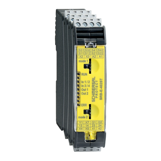
SRB-E-402ST
1
Advertisement
Table of Contents

Subscribe to Our Youtube Channel
Related Manuals for schmersal SRB-E-402ST


Summary of Contents for schmersal SRB-E-402ST
-
Page 1: Table Of Contents
Operating instructions Safety-monitoring module SRB-E-402ST Wiring examples 7.1 Possible applications ........6 7.2 Application example. -
Page 2: Appropriate Use
Only if the action described in these operating instructions is Further technical information can be found in the Schmersal carried out correctly will the safety function be safeguarded, catalogues or in the online catalogue on the Internet: including compliance with the Machinery Directive. -
Page 3: Derating / Electrical Lifespan Of Safety Contacts
Operating instructions Safety-monitoring module SRB-E-402ST Derating / electrical lifespan of safety contacts Insulation values to IEC 60664-1: Rated insulation voltageU No derating with individual installation of modules. - safety contacts: 250 V - safety outputs: Derating on request if several modules are installed one after the... -
Page 4: Mounting
Operating instructions Safety-monitoring module SRB-E-402ST 3. Mounting 5. Operating principle and settings General mounting instructions Description of the terminals and LED indications Mounting: snaps onto standard DIN rails to EN 60715. Function Function Hook bottom of enclosure in DIN rail and push down until it engages in... -
Page 5: Applications For Two Safety Functions Can Be Set Separately Using Rotary Mode Switch 1 And 2
Operating instructions Safety-monitoring module SRB-E-402ST Adjustment of application using rotary “mode” switch • Open front transparent cover (see fig.). • Opening is carried out by lifting side with lock. • Select desired application for safety function 2 using rotary mode switch 2 (1 …... -
Page 6: Diagnostic
RUN, In 1/2, In 3/4, operating voltage Out 1, Out 2 Application was LEDs flash quickly: changed during In 1/2, In 3/4, active operation Out 1, Out 2 Other fault codes: Consult technical sales dept. at Schmersal... -
Page 7: Start Configuration
Operating instructions Safety-monitoring module SRB-E-402ST Wiring example SRB-E-402ST +24VDC Safety function 1 Safety function 2 S 11 S 21 S 22 S 12 S 31 S 41 S 42 S 32 a) Safety inputs b) Safety outputs Safety function 2... -
Page 8: Sensor Configuration
Operating instructions Safety-monitoring module SRB-E-402ST Sensor configuration Dual channel signal processing NC / NO (Cat. 4 - PL e to DIN EN ISO 13849-1 possible) Single channel signal processing Safety function 1 Safety function 2 Safety function 1 S11 S21... -
Page 9: Set-Up And Maintenance
Operating instructions Safety-monitoring module SRB-E-402ST +24 VDC +24 VDC +24 VDC +24 VDC +24 VDC Maintenance A regular visual inspection and functional test, including the following steps, is recommended: 1. Check the correct fixing of the safety-monitoring module 2. Check the cable for damages 3. -
Page 10: Eu Declaration Of Conformity
Philip Schmersal Managing Director The currently valid declaration of conformity can be downloaded from the internet at www.schmersal.net. K. A. Schmersal GmbH & Co. KG Möddinghofe 30, D - 42279 Wuppertal Postfach 24 02 63, D - 42232 Wuppertal Phone:...
Need help?
Do you have a question about the SRB-E-402ST and is the answer not in the manual?
Questions and answers